US5113458A - Optical multiplexing - Google Patents
Optical multiplexing Download PDFInfo
- Publication number
- US5113458A US5113458A US07/674,909 US67490991A US5113458A US 5113458 A US5113458 A US 5113458A US 67490991 A US67490991 A US 67490991A US 5113458 A US5113458 A US 5113458A
- Authority
- US
- United States
- Prior art keywords
- fiber
- optical multiplexing
- multiplexing system
- devices
- optical
- Prior art date
- Legal status (The legal status is an assumption and is not a legal conclusion. Google has not performed a legal analysis and makes no representation as to the accuracy of the status listed.)
- Expired - Lifetime
Links
- 230000003287 optical effect Effects 0.000 title claims abstract description 28
- 239000000835 fiber Substances 0.000 claims abstract description 33
- 230000005855 radiation Effects 0.000 claims abstract description 22
- 239000013307 optical fiber Substances 0.000 claims abstract description 8
- 230000010287 polarization Effects 0.000 claims abstract description 8
- 238000000926 separation method Methods 0.000 claims abstract description 8
- 230000001939 inductive effect Effects 0.000 claims description 16
- 230000001427 coherent effect Effects 0.000 claims description 6
- 230000008878 coupling Effects 0.000 description 4
- 238000010168 coupling process Methods 0.000 description 4
- 238000005859 coupling reaction Methods 0.000 description 4
- 230000001133 acceleration Effects 0.000 description 3
- 238000000034 method Methods 0.000 description 3
- 238000010276 construction Methods 0.000 description 1
- 230000001934 delay Effects 0.000 description 1
- 230000001419 dependent effect Effects 0.000 description 1
- 230000002999 depolarising effect Effects 0.000 description 1
- 238000004804 winding Methods 0.000 description 1
Images
Classifications
-
- H—ELECTRICITY
- H04—ELECTRIC COMMUNICATION TECHNIQUE
- H04J—MULTIPLEX COMMUNICATION
- H04J14/00—Optical multiplex systems
- H04J14/02—Wavelength-division multiplex systems
-
- H—ELECTRICITY
- H04—ELECTRIC COMMUNICATION TECHNIQUE
- H04J—MULTIPLEX COMMUNICATION
- H04J14/00—Optical multiplex systems
- H04J14/06—Polarisation multiplex systems
Definitions
- This invention relates to optical multiplexing systems.
- coherence multiplexing there are various techniques of multiplexing a number of optical devices (such as sensors) some of which are described in patent GB 2184910B.
- One technique which has recently been proposed is called coherence multiplexing and may take several different forms.
- radiation consisting of partially coherent wave trains is supplied to a first channel, such as an optical fiber.
- the first channel is coupled at points along its length to a second channel, such as a second optical fiber, so that a portion of the radiation in the first channel is coupled to the second channel at each point. At the second point and succeeding points, a part of the radiation on the second channel will be coupled back into the first channel.
- the path length between adjacent points is arranged to be different for the two channels so that the primary wave train, that is, the original wave train in the first channel, reaches the demultiplexing device at the end of the channel at a different time from the secondary wave trains produced by coupling between the channels.
- Each coupling point will cause additional secondary wave trains to be produced in both channels.
- An optical sensor, or similar device is connected in one or the other of the channels, between the coupling points, so that a change in the variable being sensed causes a change in the wave trains in that channel. This arrangement produces a series array of Mach Zehnder interferometers.
- the demultiplexer is connected at the end of the second channel and takes the form of an interferometer which may operate either by comparing the primary pulse sequentially with each of the secondary pulses, or by comparing adjacent secondary pulses.
- This system suffers from a high power budget loss and crosstalk.
- An alternative arrangement for producing coherence multiplexing involves the use of a highly birefringent fiber in which the two interferometer arms of the Mach Zehnder arrangement discussed above are replaced by the two linear polarization modes of the fiber. Stressing the fiber at a point causes coupling between the two different modes.
- An interferometer can be used to identify the location of different points of stress along the fiber. This arrangement can have a lower power loss than the previous arrangement but still suffers from a relatively high crosstalk.
- a optical multiplexing system including a length of a substantially non-birefringent optical fiber and a source of partially coherent depolarized optical radiation at one end of the fiber, the system including a plurality of means for inducing birefringence in the fiber at respective points along its length such that the radiation is superimposed onto two polarization modes which results in each incoming wave train producing two output wave trains separated in time from one another, each means being separated from others of the means by a non-birefringent portion of the fiber, the time separation between output wave trains from each means differing from one another, and the system including means for measuring the time separation between output wave trains.
- the means for measuring the time separation between output wave trains is preferably a decoding interferometer.
- At least one of the means for inducing birefringence in the fiber may be a sensor such as an accelerometer. At least one of the means for inducing birefringence may be a switch or include a length of fiber wound into a coil. At least one of the means for inducing birefringence may include a length of fiber twisted about its axis or a length of fiber subject to lateral pressure. The length of fiber subject to lateral pressure may be laid in a V-shape groove and subjected to lateral pressure from a pad.
- a plurality of means for inducing birefringence may be arranged in series along the optical fiber.
- the system may include means for depolarizing radiation between two of the means for inducing birefringence. Alternatively, a plurality of means for inducing birefringence may be arranged in parallel with one another.
- the source of radiation may include a luminescent diode and a depolarizer between the diode and the one end of the fiber.
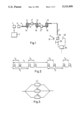
- FIG. 1 shows the system schematically
- FIG. 2 shows the output of the system
- FIG. 3 shows an alternative arrangement of the system
- FIGS. 4 and 5 show alternative sensors of the system.
- the system includes a source 1 of optical radiation, such as a super luminescent diode, which has a low coherent length and which is controlled by a drive unit 2 and produces partially coherent optical radiation.
- the radiation is supplied to a Lyot depolarizer 3 or a similar device for ensuring that the radiation is depolarized, that is, each polarization mode is equally populated.
- the depolarized radiation is supplied to one end of a conventional, non-birefringent optical fiber 4.
- the other end of the fiber extends to a demultiplexer in the form of a decoding interferometer 5 of conventional construction.
- optical sensors 11 to 13 which may be optical accelerometers of the kind described in UK Patent Application GB 2236849A.
- the sensors 11 to 13 illustrated are formed by winding the fiber 4 onto respective compliant mandrels 14 to 16. This causes a degree of birefringence to be induced into the fiber which is dependent on both the bend radius and the tension under which the fiber is coiled, with the polarization axes being defined relative to the axis of the mandrel. Acceleration causes deformation of the mandrels 14 to 16 and hence a change in the tension of the fiber and in the diameter of the mandrel which alters the birefringence.
- a partially coherent wave train entering the sensor 11 at one end is superimposed onto two polarization modes which are transmitted through the coil in different times so that a time delay T 1 is introduced between the two modes.
- the radiation enters a section 17 of non-birefringent fiber 4 where the two modes are again degenerate and appear as two wave trains pulses separated by the time T 1 .
- the wave trains may be depolarized using a further Lyot depolarizer 3'.
- each delay T 1 , T 2 and T 3 varies according to the acceleration experienced by each sensor 11 to 13 and each sensor is arranged so that, for the range of its time delay T 1 , T 2 or T 3 , the wave trains it produces will not overlap with those produced by the other two sensors.
- the interferometer 5 may take any conventional form. An illustrated, it includes a beam splitter 50 that directs a part of the incoming radiation to a fixed mirror 51 and a part to a moving mirror 52 that is scanned up and down. Radiation reflected from the two mirrors 51 and 52 passes to a detector 53. Interference will be produced at the detector 53 between the radiation from the two mirrors when the path length between the two arms of the interferometer is equal or when the path lengths differ by amounts corresponding to the time delay between different ones of the wave trains, so that radiation in one wave trains interferes with radiation in the other wave train.
- the first wave trains to interfere with one another will be the wave trains A and B, C and D, E and F, and G and H, where there is the smallest time difference between them, namely T 3 .
- wave trains B and C, D and E, and F and G will interfere which correspond to a time difference of T 2 -T 3 .
- Interference will subsequently take place between wave trains A and C, C and E, and E and G and also between B and D, C and E, and F and H which both correspond to time differences of T 2 .
- Further movement of the mirror will cause interference between different pairs of wave trains.
- the position of the movable mirror 52 at which interference is produced is measured by a unit 60 so that different ones of the sensors 11 to 13 are identified together with their time delays, and hence the acceleration, experienced at each sensor.
- optical devices could be used and that these need not be arranged in series but could, for example, be arranged in parallel, as shown at 11', 12'and 13' in FIG. 3.
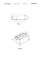
- the optical devices need not be accelerometers or other sensors but could be, for example, switches or combinations of different sensors and switches. Birefringence can be induced by the optical devices in ways other than by forming the fiber into a coil.
- the fiber 4" could be twisted about its axis, as shown in FIG. 4.
- the fiber 4"' could be laid in a V-shape groove 20 in a block 21 and subjected to lateral pressure from a pad 22, as shown in FIG. 5.
Landscapes
- Engineering & Computer Science (AREA)
- Computer Networks & Wireless Communication (AREA)
- Signal Processing (AREA)
- Optical Transform (AREA)
- Lasers (AREA)
- Optical Communication System (AREA)
Abstract
Description
Claims (11)
Applications Claiming Priority (2)
| Application Number | Priority Date | Filing Date | Title |
|---|---|---|---|
| GB909007615A GB9007615D0 (en) | 1990-04-04 | 1990-04-04 | Optical multiplexing |
| GB9007615 | 1990-04-04 |
Publications (1)
| Publication Number | Publication Date |
|---|---|
| US5113458A true US5113458A (en) | 1992-05-12 |
Family
ID=10673880
Family Applications (1)
| Application Number | Title | Priority Date | Filing Date |
|---|---|---|---|
| US07/674,909 Expired - Lifetime US5113458A (en) | 1990-04-04 | 1991-04-11 | Optical multiplexing |
Country Status (5)
| Country | Link |
|---|---|
| US (1) | US5113458A (en) |
| EP (1) | EP0450835B1 (en) |
| JP (1) | JPH05344097A (en) |
| DE (1) | DE69103661T2 (en) |
| GB (2) | GB9007615D0 (en) |
Cited By (6)
| Publication number | Priority date | Publication date | Assignee | Title |
|---|---|---|---|---|
| US5408545A (en) * | 1994-01-19 | 1995-04-18 | Dicon Fiberoptics | Depolarizer for fiber optic applications and method using same |
| US5653537A (en) * | 1995-03-17 | 1997-08-05 | Ircon, Inc. | Non-contacting infrared temperature thermometer detector apparatus |
| US5729372A (en) * | 1993-06-28 | 1998-03-17 | Fujitsu Limited | Optical transmission method and apparatus and optical amplification method and apparatus for optical communication system |
| US5812270A (en) * | 1997-09-17 | 1998-09-22 | Ircon, Inc. | Window contamination detector |
| US6301030B1 (en) * | 1998-08-14 | 2001-10-09 | Lucent Technologies, Inc. | Polarization multiplexer, demultiplexer, and method |
| US7174073B1 (en) | 2004-08-16 | 2007-02-06 | The United States Of America As Represented By The Secretary Of The Navy | Multiple-tapped optical delay line |
Citations (9)
| Publication number | Priority date | Publication date | Assignee | Title |
|---|---|---|---|---|
| US3991318A (en) * | 1973-09-28 | 1976-11-09 | Bell Telephone Laboratories, Incorporated | Optical detection systems utilizing organ arrays of optical fibers |
| US4367040A (en) * | 1979-05-29 | 1983-01-04 | Tokyo Shibaura Denki Kabushiki Kaisha | Multi-channel optical sensing system |
| GB2165118A (en) * | 1984-09-29 | 1986-04-03 | Plessey Co Plc | OTDR for sensing distortions in optical fibres |
| GB2184910A (en) * | 1985-12-18 | 1987-07-01 | Smiths Industries Plc | Optical multiplex system |
| EP0251632A2 (en) * | 1986-06-23 | 1988-01-07 | The Board Of Trustees Of The Leland Stanford Junior University | Distributed sensor array and method using a pulsed signal source |
| US4749254A (en) * | 1985-04-03 | 1988-06-07 | Seaver George A | Optical sensor system |
| US4818064A (en) * | 1987-09-24 | 1989-04-04 | Board Of Trustees Stanford Junior University | Sensor array and method of selective interferometric sensing by use of coherence synthesis |
| US4882716A (en) * | 1988-01-25 | 1989-11-21 | Thomson-Csf | Optic fiber hydrophone and antenna associating a series of hydrophones |
| GB2236849A (en) * | 1989-09-21 | 1991-04-17 | Smiths Industries Plc | Opto-electronic accelerometer |
Family Cites Families (1)
| Publication number | Priority date | Publication date | Assignee | Title |
|---|---|---|---|---|
| US4889986A (en) * | 1988-08-18 | 1989-12-26 | The United States Of America As Represented By The Secretary Of The Navy | Serial interferometric fiber-optic sensor array |
-
1990
- 1990-04-04 GB GB909007615A patent/GB9007615D0/en active Pending
-
1991
- 1991-03-26 DE DE69103661T patent/DE69103661T2/en not_active Expired - Fee Related
- 1991-03-26 EP EP91302623A patent/EP0450835B1/en not_active Expired - Lifetime
- 1991-03-27 GB GB9106492A patent/GB2243907B/en not_active Expired - Fee Related
- 1991-04-04 JP JP3097995A patent/JPH05344097A/en active Pending
- 1991-04-11 US US07/674,909 patent/US5113458A/en not_active Expired - Lifetime
Patent Citations (9)
| Publication number | Priority date | Publication date | Assignee | Title |
|---|---|---|---|---|
| US3991318A (en) * | 1973-09-28 | 1976-11-09 | Bell Telephone Laboratories, Incorporated | Optical detection systems utilizing organ arrays of optical fibers |
| US4367040A (en) * | 1979-05-29 | 1983-01-04 | Tokyo Shibaura Denki Kabushiki Kaisha | Multi-channel optical sensing system |
| GB2165118A (en) * | 1984-09-29 | 1986-04-03 | Plessey Co Plc | OTDR for sensing distortions in optical fibres |
| US4749254A (en) * | 1985-04-03 | 1988-06-07 | Seaver George A | Optical sensor system |
| GB2184910A (en) * | 1985-12-18 | 1987-07-01 | Smiths Industries Plc | Optical multiplex system |
| EP0251632A2 (en) * | 1986-06-23 | 1988-01-07 | The Board Of Trustees Of The Leland Stanford Junior University | Distributed sensor array and method using a pulsed signal source |
| US4818064A (en) * | 1987-09-24 | 1989-04-04 | Board Of Trustees Stanford Junior University | Sensor array and method of selective interferometric sensing by use of coherence synthesis |
| US4882716A (en) * | 1988-01-25 | 1989-11-21 | Thomson-Csf | Optic fiber hydrophone and antenna associating a series of hydrophones |
| GB2236849A (en) * | 1989-09-21 | 1991-04-17 | Smiths Industries Plc | Opto-electronic accelerometer |
Non-Patent Citations (1)
| Title |
|---|
| J. Phys E: Sci Instrum 20 (1987) p. 960. * |
Cited By (6)
| Publication number | Priority date | Publication date | Assignee | Title |
|---|---|---|---|---|
| US5729372A (en) * | 1993-06-28 | 1998-03-17 | Fujitsu Limited | Optical transmission method and apparatus and optical amplification method and apparatus for optical communication system |
| US5408545A (en) * | 1994-01-19 | 1995-04-18 | Dicon Fiberoptics | Depolarizer for fiber optic applications and method using same |
| US5653537A (en) * | 1995-03-17 | 1997-08-05 | Ircon, Inc. | Non-contacting infrared temperature thermometer detector apparatus |
| US5812270A (en) * | 1997-09-17 | 1998-09-22 | Ircon, Inc. | Window contamination detector |
| US6301030B1 (en) * | 1998-08-14 | 2001-10-09 | Lucent Technologies, Inc. | Polarization multiplexer, demultiplexer, and method |
| US7174073B1 (en) | 2004-08-16 | 2007-02-06 | The United States Of America As Represented By The Secretary Of The Navy | Multiple-tapped optical delay line |
Also Published As
| Publication number | Publication date |
|---|---|
| EP0450835A3 (en) | 1992-09-16 |
| EP0450835A2 (en) | 1991-10-09 |
| EP0450835B1 (en) | 1994-08-31 |
| DE69103661T2 (en) | 1994-12-22 |
| GB9106492D0 (en) | 1991-05-15 |
| GB9007615D0 (en) | 1990-05-30 |
| GB2243907B (en) | 1993-12-15 |
| DE69103661D1 (en) | 1994-10-06 |
| JPH05344097A (en) | 1993-12-24 |
| GB2243907A (en) | 1991-11-13 |
Similar Documents
| Publication | Publication Date | Title |
|---|---|---|
| US5757487A (en) | Methods and apparatus for distributed optical fiber sensing of strain or multiple parameters | |
| US6314056B1 (en) | Fiber optic sensor system and method | |
| US4950883A (en) | Fiber optic sensor arrangement having reflective gratings responsive to particular wavelengths | |
| JP2531940B2 (en) | Method for fiber optic transmission of spectrally coded values of variable physical measurands and apparatus for implementing the method | |
| US6072567A (en) | Vertical seismic profiling system having vertical seismic profiling optical signal processing equipment and fiber Bragg grafting optical sensors | |
| US5426297A (en) | Multiplexed Bragg grating sensors | |
| US4653916A (en) | Optical sensing systems | |
| US5118931A (en) | Fiber optic microbending sensor arrays including microbend sensors sensitive over different bands of wavelengths of light | |
| US5380995A (en) | Fiber optic grating sensor systems for sensing environmental effects | |
| US5680489A (en) | Optical sensor system utilizing bragg grating sensors | |
| US5475216A (en) | Fiber optic sensor having mandrel wound reference and sensing arms | |
| US4773758A (en) | Sensor using fiber interferometer | |
| US8988968B2 (en) | Seismic cable structure | |
| EP1218710A1 (en) | Device for measuring of optical wavelengths | |
| NO860432L (en) | DISTRIBUTED SENSORS AND PROCEDURES USING CONNECTION MULTIPLEXING OF FIBER-OPTICAL INTERFEROMETRIC SENSORS. | |
| NO324687B1 (en) | Interferometer array for implementation of serial fiber Bragg grid interferometer array, and optical fiber system utilizing this | |
| US5113458A (en) | Optical multiplexing | |
| JPH01238297A (en) | Optical fiber hydrophone and antenna connected to a series of hydrophones | |
| AU613497B2 (en) | An interferometric fibre optic network | |
| US5072113A (en) | Polarimetric fibre-optic sensor having deformation means | |
| US8499638B2 (en) | Fibre optic accelerometer and a method of manufacturing a fibre optic accelerometer | |
| KR910005303B1 (en) | Sensor using fiber optic interferometer | |
| USRE34604E (en) | Sensor using fiber interferometer | |
| Dokulilová et al. | Strain sensor with low-temperature sensitivity based on a weakly multimode optical fibre using coherence multiplexing | |
| Yuan | Modified Michelson fiber-optic interferometer: A remote low-coherence distributed strain sensor array |
Legal Events
| Date | Code | Title | Description |
|---|---|---|---|
| AS | Assignment |
Owner name: SMITHS INDUSTRIES PUBLIC LIMITED COMPANY, ENGLAND Free format text: ASSIGNMENT OF ASSIGNORS INTEREST.;ASSIGNOR:TAYLOR, ROBERT MYLES;REEL/FRAME:006024/0089 Effective date: 19920124 |
|
| STCF | Information on status: patent grant |
Free format text: PATENTED CASE |
|
| FEPP | Fee payment procedure |
Free format text: PAYOR NUMBER ASSIGNED (ORIGINAL EVENT CODE: ASPN); ENTITY STATUS OF PATENT OWNER: LARGE ENTITY |
|
| FPAY | Fee payment |
Year of fee payment: 4 |
|
| FPAY | Fee payment |
Year of fee payment: 8 |
|
| AS | Assignment |
Owner name: SMITHS GROUP PLC, ENGLAND Free format text: CHANGE OF NAME;ASSIGNOR:SMITHS INDUSTRIES PLC;REEL/FRAME:011566/0432 Effective date: 20001130 |
|
| AS | Assignment |
Owner name: QED INTELLECTUAL PROPERTY SERVICES LIMITED, ENGLAN Free format text: ASSIGNMENT OF ASSIGNORS INTEREST;ASSIGNOR:SMITHS GROUP;REEL/FRAME:012333/0362 Effective date: 20010711 |
|
| REMI | Maintenance fee reminder mailed | ||
| REIN | Reinstatement after maintenance fee payment confirmed | ||
| FPAY | Fee payment |
Year of fee payment: 12 |
|
| SULP | Surcharge for late payment | ||
| FP | Lapsed due to failure to pay maintenance fee |
Effective date: 20040512 |
|
| FEPP | Fee payment procedure |
Free format text: PETITION RELATED TO MAINTENANCE FEES FILED (ORIGINAL EVENT CODE: PMFP); ENTITY STATUS OF PATENT OWNER: LARGE ENTITY |
|
| FEPP | Fee payment procedure |
Free format text: PETITION RELATED TO MAINTENANCE FEES GRANTED (ORIGINAL EVENT CODE: PMFG); ENTITY STATUS OF PATENT OWNER: LARGE ENTITY |
|
| PRDP | Patent reinstated due to the acceptance of a late maintenance fee |
Effective date: 20060710 |