US511019A - Electric-railway trolley - Google Patents
Electric-railway trolley Download PDFInfo
- Publication number
- US511019A US511019A US511019DA US511019A US 511019 A US511019 A US 511019A US 511019D A US511019D A US 511019DA US 511019 A US511019 A US 511019A
- Authority
- US
- United States
- Prior art keywords
- trolley
- wire
- boot
- car
- electric
- Prior art date
- Legal status (The legal status is an assumption and is not a legal conclusion. Google has not performed a legal analysis and makes no representation as to the accuracy of the status listed.)
- Expired - Lifetime
Links
- 239000011810 insulating material Substances 0.000 description 2
- 239000002184 metal Substances 0.000 description 2
- 238000010276 construction Methods 0.000 description 1
- 230000037361 pathway Effects 0.000 description 1
- 239000007787 solid Substances 0.000 description 1
Images
Classifications
-
- B—PERFORMING OPERATIONS; TRANSPORTING
- B60—VEHICLES IN GENERAL
- B60L—PROPULSION OF ELECTRICALLY-PROPELLED VEHICLES; SUPPLYING ELECTRIC POWER FOR AUXILIARY EQUIPMENT OF ELECTRICALLY-PROPELLED VEHICLES; ELECTRODYNAMIC BRAKE SYSTEMS FOR VEHICLES IN GENERAL; MAGNETIC SUSPENSION OR LEVITATION FOR VEHICLES; MONITORING OPERATING VARIABLES OF ELECTRICALLY-PROPELLED VEHICLES; ELECTRIC SAFETY DEVICES FOR ELECTRICALLY-PROPELLED VEHICLES
- B60L5/00—Current collectors for power supply lines of electrically-propelled vehicles
- B60L5/04—Current collectors for power supply lines of electrically-propelled vehicles using rollers or sliding shoes in contact with trolley wire
- B60L5/12—Structural features of poles or their bases
- B60L5/16—Devices for lifting and resetting the collector
-
- B—PERFORMING OPERATIONS; TRANSPORTING
- B60—VEHICLES IN GENERAL
- B60L—PROPULSION OF ELECTRICALLY-PROPELLED VEHICLES; SUPPLYING ELECTRIC POWER FOR AUXILIARY EQUIPMENT OF ELECTRICALLY-PROPELLED VEHICLES; ELECTRODYNAMIC BRAKE SYSTEMS FOR VEHICLES IN GENERAL; MAGNETIC SUSPENSION OR LEVITATION FOR VEHICLES; MONITORING OPERATING VARIABLES OF ELECTRICALLY-PROPELLED VEHICLES; ELECTRIC SAFETY DEVICES FOR ELECTRICALLY-PROPELLED VEHICLES
- B60L2200/00—Type of vehicles
- B60L2200/26—Rail vehicles
Definitions
- My invention has relation to overhead electric trolleys for cars, and its object is to provide a trolley which will conduct the current from the wire overhead to the wire connected with the motors of the car, with as little friction as possible and at the same time making a perfect connection and thereby wasting none of the current.
- My invention is also designed to provide a trolley that can be easily swung around when the car is reversed, said trolley consisting in the novel construction and arrangements of its parts as hereinafter described.
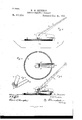
- Figure 1 is a side view of my invention attached to the top of the car.
- Fig. 2 is a top plan view of Fig. 1, the trolley being removed.
- Fig. 8 is a view of Fig. l, partly in section; and
- Fig. 4 is a detailed perspective view of the spring that keeps the trolley against the wire.
- I represents the top of the car, and to the top of the car is secured the circular path 2.
- This circular path can be a flat surface or a solid cylindrically shaped rod as shown in the drawings, the essential feature being that the path is circular.
- the said path is insulated from the top of the car by the insulating material 3, which is between said path and the said top of the car.
- Connecting the circular path is the wire 4, (see Fig. 1,) which conducts the current to the motors.
- This wire can pass around or over the car as desired.
- the pivot 5 In the center of the car and in the center of the said circular path is the pivot 5, which is also provided on its under side with insulating material 3.
- the support 6, which in turn is rigidly secured to the front end of the upper side of the boot 7.
- any desirable connection can be made without departing from the spirit of the invention.
- the pivot can be made in two pieces or sections and put around the end of support 6, thus making a dovetail joint.
- the boot 7, is pref erably made of sheet metal having on each longitudinal side a perpendicular flange 8, and to the rear end and under side of the said boot are rigidly secured suitable lugs 9,;having journaled between them rollers or wheels 10; said wheels 10, are adapted to run on the circular path 2.
- the said path 2 is flat the peripheries of the wheels 10, will be flat, but if the path is convex or concave the peripheries of the Wheels will be made to conform to the surface of the path.
- the wire 12 is adapted to conduct the current down the trolley pole, and the lower end of the said wire may be twisted around the pivot of the said pole and as said pivot is connected with the perpendicular flanges of the boot, the current will pass into the boot, and from thence by means of the wheels 10, to the circular pathway 2, which is connected with the wire 4:.
- I may use any known or desirable means.
- a pcculiar coil spring which can be used to great advantage in keeping the trolley wheelagainst the wire.
- Said spring is constructed of one continuous piece of metal, as shown in Fig. 4. The end 13, of the said spring rests in the bottom of the boot; the coil 14, runs around the pivot of the trolley pole 11; and the end 15, bears against the under side of the said trolley pole.
- the trolley pole is pro vided with a metallic plate 16, against which the end 15, of the said spring bears and thereby said spring is prevented from wearing the under side of the pole.
- the trolley wheel is firmly kept against the overhead wire.
Landscapes
- Engineering & Computer Science (AREA)
- Power Engineering (AREA)
- Transportation (AREA)
- Mechanical Engineering (AREA)
- Current-Collector Devices For Electrically Propelled Vehicles (AREA)
Description
(No Model.)
W. W. HENDRIX. ELEGTRIG RAILWAY TROLLEY.
Patented Dec. l9, 1893.
moawbo'z W W H en d 141, 5?] WM x @1206 is mss THE NATIONAL umoannmnn ccnPAuY.
ION. o. c.
wAamu-m UNITED STATES PATENT OFFICE.
WILLIAM XV. HENDRIX, OF BOWLING GREEN, KENTUCKY. v
ELECTRIC-RAILWAY TROLLEY.
SLPEGIFIGATION forming part of Letters Patent No. 511,019, dated December 19, 1893.
Application filed October 7, 1892. Renewed November 22, 1893.' Serial No. 491,685. (No model.)
To aZZ whom it may concern:
Be it known that I, WILLIAM W. HENDRIX, a citizen of the United States, residing at Bowling Grcemin the county of l-Varren and State of Kentucky, have invented a certain new, useful, and valuable Improvement in Overhead Trolleys, of which the following is a full, clear, and exact description.
My invention has relation to overhead electric trolleys for cars, and its object is to provide a trolley which will conduct the current from the wire overhead to the wire connected with the motors of the car, with as little friction as possible and at the same time making a perfect connection and thereby wasting none of the current.
My invention is also designed to provide a trolley that can be easily swung around when the car is reversed, said trolley consisting in the novel construction and arrangements of its parts as hereinafter described.
In the accompanying drawings: Figure 1, is a side view of my invention attached to the top of the car. Fig. 2, is a top plan view of Fig. 1, the trolley being removed. Fig. 8, is a view of Fig. l, partly in section; and Fig. 4, is a detailed perspective view of the spring that keeps the trolley against the wire.
My invention is described as follows:
I, represents the top of the car, and to the top of the car is secured the circular path 2. This circular path can be a flat surface or a solid cylindrically shaped rod as shown in the drawings, the essential feature being that the path is circular. The said path is insulated from the top of the car by the insulating material 3, which is between said path and the said top of the car. Connecting the circular path is the wire 4, (see Fig. 1,) which conducts the current to the motors. This wire can pass around or over the car as desired. In the center of the car and in the center of the said circular path is the pivot 5, which is also provided on its under side with insulating material 3. To the top of the pivot 5, is swiveled the support 6, which in turn is rigidly secured to the front end of the upper side of the boot 7. In swiveling the support 6, to the pivot 5, any desirable connection can be made without departing from the spirit of the invention. In Fig. 3, of the drawings the pivot can be made in two pieces or sections and put around the end of support 6, thus making a dovetail joint. The boot 7, is pref erably made of sheet metal having on each longitudinal side a perpendicular flange 8, and to the rear end and under side of the said boot are rigidly secured suitable lugs 9,;having journaled between them rollers or wheels 10; said wheels 10, are adapted to run on the circular path 2. If the said path 2, is flat the peripheries of the wheels 10, will be flat, but if the path is convex or concave the peripheries of the Wheels will be made to conform to the surface of the path. Between the perpendicular flanges 8, of the said boot and near its front end is pivoted the lower end of the trolley pole 11, the upper end of said trolley pole being provided with the ordinary trolley Wheel to bear against the overhead wire. The wire 12, is adapted to conduct the current down the trolley pole, and the lower end of the said wire may be twisted around the pivot of the said pole and as said pivot is connected with the perpendicular flanges of the boot, the current will pass into the boot, and from thence by means of the wheels 10, to the circular pathway 2, which is connected with the wire 4:.
To keep the trolley wheel against the overhead wire I may use any known or desirable means. In the drawings I have shown a pcculiar coil spring which can be used to great advantage in keeping the trolley wheelagainst the wire. Said spring is constructed of one continuous piece of metal, as shown in Fig. 4. The end 13, of the said spring rests in the bottom of the boot; the coil 14, runs around the pivot of the trolley pole 11; and the end 15, bears against the under side of the said trolley pole.
As shown in Fig. 3, the trolley pole is pro vided with a metallic plate 16, against which the end 15, of the said spring bears and thereby said spring is prevented from wearing the under side of the pole. Thus the trolley wheel is firmly kept against the overhead wire.
Having thus described my inventiomwhat I claim as new, and desire to secure by Letters the boot, substantially as shown and de- Patent, is scribed. [0
An overhead trolley having its lower end In testimony whereofI affix my signature in pivoted in a swiveled boot, the trolley pole presence of two Witnesses.
5 having bearing against its under side one end WM. W. HENDRIX.
of the coiled spring, the coils of said spring \Vihnesses: passing around the pivot and the other end JNO. G. COOKE,
of the spring bearing against the bottom of FRANK E. COOKsEY.
Publications (1)
| Publication Number | Publication Date |
|---|---|
| US511019A true US511019A (en) | 1893-12-19 |
Family
ID=2579846
Family Applications (1)
| Application Number | Title | Priority Date | Filing Date |
|---|---|---|---|
| US511019D Expired - Lifetime US511019A (en) | Electric-railway trolley |
Country Status (1)
| Country | Link |
|---|---|
| US (1) | US511019A (en) |
-
0
- US US511019D patent/US511019A/en not_active Expired - Lifetime
Similar Documents
| Publication | Publication Date | Title |
|---|---|---|
| US511019A (en) | Electric-railway trolley | |
| US457105A (en) | boynton | |
| US435166A (en) | Trolley or contact-support for electric cars | |
| US554517A (en) | Iialf to frederic cunningham | |
| US722189A (en) | Trolley-wheel for electric tram-cars. | |
| US520758A (en) | William lawrence | |
| US688629A (en) | Trolley-wheel guard. | |
| US709168A (en) | Trolley. | |
| US445409A (en) | Turn-out for electric railways | |
| US621321A (en) | Electric-railway system | |
| US554350A (en) | Half to frederic cunningham | |
| US532157A (en) | Paul c | |
| US1110783A (en) | Trolley-wheel. | |
| US428930A (en) | Suspension for trolley-wires | |
| US457334A (en) | The kohris petebj co | |
| US688509A (en) | Trolley. | |
| US960829A (en) | Trolley for electric railways. | |
| US459689A (en) | Sidney h | |
| US610008A (en) | Contact bail | |
| US582259A (en) | William milton brown | |
| US606825A (en) | Contact device for electric railways | |
| US427589A (en) | Guide for trolley-wheels | |
| US1029770A (en) | Operating device for street-indicators. | |
| US886645A (en) | Trolley-guard. | |
| US653402A (en) | Safety-trolley. |