US5110144A - Casing hanger seal assembly - Google Patents
Casing hanger seal assembly Download PDFInfo
- Publication number
- US5110144A US5110144A US07/573,630 US57363090A US5110144A US 5110144 A US5110144 A US 5110144A US 57363090 A US57363090 A US 57363090A US 5110144 A US5110144 A US 5110144A
- Authority
- US
- United States
- Prior art keywords
- sealing
- energizer
- lip
- seal
- assembly according
- Prior art date
- Legal status (The legal status is an assumption and is not a legal conclusion. Google has not performed a legal analysis and makes no representation as to the accuracy of the status listed.)
- Expired - Lifetime
Links
Images


Classifications
-
- E—FIXED CONSTRUCTIONS
- E21—EARTH OR ROCK DRILLING; MINING
- E21B—EARTH OR ROCK DRILLING; OBTAINING OIL, GAS, WATER, SOLUBLE OR MELTABLE MATERIALS OR A SLURRY OF MINERALS FROM WELLS
- E21B33/00—Sealing or packing boreholes or wells
- E21B33/02—Surface sealing or packing
- E21B33/03—Well heads; Setting-up thereof
- E21B33/04—Casing heads; Suspending casings or tubings in well heads
-
- Y—GENERAL TAGGING OF NEW TECHNOLOGICAL DEVELOPMENTS; GENERAL TAGGING OF CROSS-SECTIONAL TECHNOLOGIES SPANNING OVER SEVERAL SECTIONS OF THE IPC; TECHNICAL SUBJECTS COVERED BY FORMER USPC CROSS-REFERENCE ART COLLECTIONS [XRACs] AND DIGESTS
- Y10—TECHNICAL SUBJECTS COVERED BY FORMER USPC
- Y10S—TECHNICAL SUBJECTS COVERED BY FORMER USPC CROSS-REFERENCE ART COLLECTIONS [XRACs] AND DIGESTS
- Y10S285/00—Pipe joints or couplings
- Y10S285/917—Metallic seals
Definitions
- the present invention relates to an improved wellhead structure which is particularly adapted to subsea wells.
- Such structure includes a wellhead housing and an improved hanger and seal assembly which can be landed and set in a single trip.
- the R. W. Walker U.S. Pat. No. 3,273,646 discloses a hanger and seal assembly in which a snap ring is used to engage within a groove within the interior of the housing and the seal is run in the annulus above a port which allows the circulation of cement to proceed before the seal is set responsive to rotation of the setting sleeve to force the seal downward below the port and to land on a shoulder against which it is compressed axially to cause it to expand radially and seal across the annulus.
- the B. H. Nelson et al U.S. Pat. No. 3,404,736 discloses an annulus seal in which the seal is positioned within the annulus and held in the unset position by a shear pin.
- the rotation of the setting sleeve causes the pin to shear and the seal and wedge ring to move downward to set the holddown ring and to compress the resilient seal into sealing engagement with the walls of the annulus.
- the J. H. Hynes et al U.S. Pat. No. 3,797,864 discloses another annulus seal which is set by rotation to compress the seal axially.
- This seal assembly includes end rings with marginal lips which engage the end of the elastomeric seal and when the seal is compressed the lips are deformed into metal-to-metal sealing engagement with the walls of the annulus.
- the Slyker et al U.S. Pat. No. 4,521,040 discloses a modification of the Hynes et al structure.
- Another hanger seal which is set by threading a nut on external threads of the hanger includes a seal body having a plurality of outer metal fins extending outwardly and downwardly and having elastomeric material between the fins, a plurality of inner metal fins extending radially inward and having elastomeric material between the fins and a connection between the seal body and a lower body having an upstanding rim which when the bodies are forced together sets the outer seal legs.
- Another hanger nut thread set seal includes both inner and outer seal legs which diverge and are loaded by inner and outer rims on the upper body and lower body to set all four seal legs into sealing engagement with the walls of the housing-hanger annulus.
- the improved structure of the present invention relates to an improved hanger seal assembly for sealing between a hanger and a well housing.
- the hanger is landed within the well housing before the seal assembly is moved into sealing position between the housing and the hanger.
- the seal assembly is lowered into sealing position between an external hanger sealing surface spaced from the internal housing sealing surface which is defined within a recess on the interior of the well housing and includes a seal body having external metal sealing lips diverging outwardly but having an initial free diameter less than the diameter of the housing internal sealing surface and internal metal sealing surfaces on the inner surface of the body having a free diameter smaller than the diameter of the hanger external sealing surface, a lower energizer ring movably connected to the seal body and having an upstanding rim which stores the force created by its engaging and moving the lower outer sealing lip to its set position, an upper energizer ring movably connected to the seal body and having a depending rim which stores the force created by its engaging and moving the upper lip to its set position.
- the upper and lower sealing lips are of an annealed or soft metal while the upper and lower energizer bodies are of a high yield strength metal so that the loading force on the lips can be stored and maintained after they are set into sealing position.
- the interior projections which provide the interior sealing are spaced along the interior of the seal body by recesses which are either sufficiently deep to avoid problems with liquids trapped therein during setting or have a liquid exclusion material therein.
- Means for securing or locking the seal assembly and the energizer rings in their set position is included and such securing means includes means for engaging within grooves on the exterior of the hanger and on the interior of the housing.
- some means for storing the lip setting force and this may include the storing of both axial and radial forces generated for setting the sealing lips.
- An object of the present invention is to provide an improved hanger seal assembly for use within a wellhead housing with improved metal-to-metal sealing against the inner and outer surfaces of the hanger-housing annulus and which stores the setting energy to retain the metal-to-metal seal.
- FIG. 1 is a sectional elevation view of a hanger landed within a well housing and the improved seal assembly of the present invention being in position for lowering into sealing position across the annulus between the hanger external sealing surface and the well housing internal sealing surface.
- FIG. 3 is a detailed partial sectional view of the seal assembly of the present invention in its unset position.
- FIG. 4 is a detailed partial sectional view of the seal assembly shown in FIG. 3 after it has been moved to its set position.
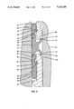
- FIG. 4A is a partial enlarged sectional view of the lower seal lip and its energizing ring as shown in FIG. 4.
- Improved seal assembly 10 of the present invention is illustrated while being lowered within well housing 12 and into annulus 14 between the interior of well housing 12 and the exterior of hanger 16 which has been landed within well housing 12.
- hangers 16A and 16B have previously been landed within housing 12 and their respective seal assemblies 10A and 10B have been landed in the respective annuli 14A and 14B.
- Seal assembly 10 is supported from setting assembly 18 and setting assembly 18 is supported on a suitable tool (not shown) which can move the setting assembly 18 after landing into its set position as hereinafter described.
- Seal assembly 10 includes annular body 20, lower energizer ring 22, and upper energizer ring 24.
- Lower energizer ring 22 is movably attached to lower rim 26 of body 20 by split ring 28 which is positioned in groove 30 on the interior of energizer ring 22 and in elongated groove 32 in the exterior of lower body rim 26. This allows relative axial movement of energizer ring 22 with respect to body 20.
- Upper energizer ring 24 is movably attached to upper rim 34 of body 20 by split ring 36 which is positioned in groove 38 on the interior of energizer ring 24 and in elongated groove 40 on the exterior of upper body rim 34. This allows relative axial movement of energizer ring 24 with respect to body 20.
- Seal body 20 includes upper annular lip 74 and lower annular lip 76.
- Upper annular lip 74 extends outward from the exterior of body 20 and then curves to a generally axial upward position.
- Lower annular lip 76 extends outward from the exterior of body 20 and then bends to a generally axial downward position. In running position the exterior diameter of lips 74 and 76 is smaller than the inner diameter of housing 12.
- Upper energizer ring 24 has its inner surface spaced slightly outward from the exterior surface of upper rim 34 and a lower tapered surface 78 which engages the inner surface of upper lip 74 during setting to move it radially outward to the set position in metal-to-metal sealing engagement with the interior surface of housing 12.
- One of the improvements of the present invention is the use of a high yield strength steel for energizer rings 22 and 24 and using a lower yield strength steel for upper and lower lips 74 and 76.
- This allows lips 74 and 76 to have sufficient give when forced against the interior of housing 12 to flow into the flaws and irregularities of such surface and ensure that there is complete metal-to-metal sealing.
- the interior of body 20 includes a series of annular ridges 82 separated by grooves 84.
- the inner diameters of ridges 82 are smaller than the diameter of the exterior portion of hanger 16 against which seal body 20 is to engage and seal. Care should be taken with the depth of grooves 84 to avoid problems with the build-up of pressure in liquids trapped therein during setting so that the sealing loads of the ridges 82 are not reduced thereby.
- grooves 84 have a radial dimension of approximately 0.005" a water exclusion material or a volume compensating material (such as a plurality of microspheres in an epoxy matrix) should be provided in grooves 84 so that the water pressure developed therein does not interfere or lessen the sealing load of the ridges 82 against the exterior surface of hanger 16. If there is some objection to the use of such materials, then it is suggested that the depth of grooves 84 be at least 0.040". Upper resilient sealing ring 86 is positioned in upper groove 88 and lower resilient sealing ring 90 is positioned in lower groove 92. Sealing rings 86 and 90 provide supplemental sealing between the interior of seal body 20 and the exterior of hanger 16.
Landscapes
- Geology (AREA)
- Life Sciences & Earth Sciences (AREA)
- Engineering & Computer Science (AREA)
- Mining & Mineral Resources (AREA)
- Geochemistry & Mineralogy (AREA)
- Fluid Mechanics (AREA)
- Environmental & Geological Engineering (AREA)
- General Life Sciences & Earth Sciences (AREA)
- Physics & Mathematics (AREA)
- Gasket Seals (AREA)
- Joints With Sleeves (AREA)
- Glass Compositions (AREA)
- Holders For Apparel And Elements Relating To Apparel (AREA)
- Sealing Devices (AREA)
- Earth Drilling (AREA)
- Auxiliary Devices For And Details Of Packaging Control (AREA)
- Outer Garments And Coats (AREA)
Abstract
Description
Claims (12)
Priority Applications (9)
| Application Number | Priority Date | Filing Date | Title |
|---|---|---|---|
| US07/573,630 US5110144A (en) | 1990-08-24 | 1990-08-24 | Casing hanger seal assembly |
| CA002037065A CA2037065C (en) | 1990-08-24 | 1991-02-26 | Casing hanger seal assembly |
| EP91301642A EP0475557B1 (en) | 1990-08-24 | 1991-02-28 | Method of sealing a casing hanger in a wellhead |
| DE69115397T DE69115397T2 (en) | 1990-08-24 | 1991-02-28 | Process for sealing a casing hanger in a wellhead |
| AT91301642T ATE131573T1 (en) | 1990-08-24 | 1991-02-28 | METHOD FOR SEALING A TUBE HANGER IN A WELL HEAD |
| AU72948/91A AU630791B2 (en) | 1990-08-24 | 1991-03-15 | Casing hanger seal assembly |
| BR919101566A BR9101566A (en) | 1990-08-24 | 1991-04-18 | SEALING ASSEMBLY FOR SEALING THE INTERIOR SEALING SURFACE OF A POCO HOUSING AND THE EXTERNAL SEALING SURFACE OF A SUSPENSOR SITTING INSIDE THE POCO HOUSING |
| JP3086493A JP2966131B2 (en) | 1990-08-24 | 1991-04-18 | Casing hanger sealing assembly |
| NO910112A NO304803B1 (en) | 1990-08-24 | 1991-08-23 | Procedure for sealing a casing in a wellhead |
Applications Claiming Priority (1)
| Application Number | Priority Date | Filing Date | Title |
|---|---|---|---|
| US07/573,630 US5110144A (en) | 1990-08-24 | 1990-08-24 | Casing hanger seal assembly |
Publications (1)
| Publication Number | Publication Date |
|---|---|
| US5110144A true US5110144A (en) | 1992-05-05 |
Family
ID=24292775
Family Applications (1)
| Application Number | Title | Priority Date | Filing Date |
|---|---|---|---|
| US07/573,630 Expired - Lifetime US5110144A (en) | 1990-08-24 | 1990-08-24 | Casing hanger seal assembly |
Country Status (9)
| Country | Link |
|---|---|
| US (1) | US5110144A (en) |
| EP (1) | EP0475557B1 (en) |
| JP (1) | JP2966131B2 (en) |
| AT (1) | ATE131573T1 (en) |
| AU (1) | AU630791B2 (en) |
| BR (1) | BR9101566A (en) |
| CA (1) | CA2037065C (en) |
| DE (1) | DE69115397T2 (en) |
| NO (1) | NO304803B1 (en) |
Cited By (23)
| Publication number | Priority date | Publication date | Assignee | Title |
|---|---|---|---|---|
| US5247997A (en) * | 1992-04-10 | 1993-09-28 | Cooper Industries, Inc. | Tubing hanger with a preloaded lockdown |
| US5307879A (en) * | 1993-01-26 | 1994-05-03 | Abb Vetco Gray Inc. | Positive lockdown for metal seal |
| US5325925A (en) * | 1992-06-26 | 1994-07-05 | Ingram Cactus Company | Sealing method and apparatus for wellheads |
| US5370153A (en) * | 1993-12-16 | 1994-12-06 | Abb Vetco Gray Inc. | Metal seal hydraulic coupling |
| US5375812A (en) * | 1993-12-06 | 1994-12-27 | Abb Vetco Gray Inc. | Dynamic metal-to-metal seal |
| US5542475A (en) * | 1994-12-01 | 1996-08-06 | Cooper Cameron Corporation | Blanking plug assembly |
| US6176310B1 (en) | 1999-02-19 | 2001-01-23 | Erc Industries, Inc. | Assembly for sealing the annulus between concentric cylindrical surfaces |
| US6705615B2 (en) | 2001-10-31 | 2004-03-16 | Dril-Quip, Inc. | Sealing system and method |
| US20050023866A1 (en) * | 2003-07-30 | 2005-02-03 | Cooper Cameron Corporation | Non-rotational casing hanger and seal assembly running tool |
| US20060191680A1 (en) * | 2005-02-09 | 2006-08-31 | Vetco Gray Inc. | Metal-to-metal seal for bridging hanger or tieback connection |
| US20080029966A1 (en) * | 2005-06-14 | 2008-02-07 | More Dominick G | Seal assembly |
| US20080265517A1 (en) * | 2007-04-26 | 2008-10-30 | Vetco Gray Inc. | System, method, and apparatus for energizable metal seals in well heads |
| US20100126736A1 (en) * | 2008-11-25 | 2010-05-27 | Vetco Gray Inc. | Bi-Directional Annulus Seal |
| US20100276162A1 (en) * | 2008-11-11 | 2010-11-04 | Vetco Gray Inc. | Metal Annulus Seal |
| US20110227296A1 (en) * | 2010-03-22 | 2011-09-22 | Fmc Technologies, Inc. | Bi-directional seal assembly |
| US20110240307A1 (en) * | 2008-03-28 | 2011-10-06 | Cameron International Corporation | Wellhead Hanger Shoulder |
| US20130207349A1 (en) * | 2012-02-09 | 2013-08-15 | Cameron International Corporation | Lip Seal |
| US20130248196A1 (en) * | 2012-03-23 | 2013-09-26 | Vetco Gray Inc. | High-capacity single-trip lockdown bushing and a method to operate the same |
| WO2017117180A1 (en) * | 2015-12-29 | 2017-07-06 | Cameron International Corporation | Hybrid wellhead connector |
| EP2483523A4 (en) * | 2009-10-01 | 2017-07-26 | Longyear TM, Inc. | Pump-in seal |
| US10184311B2 (en) | 2015-10-21 | 2019-01-22 | Vetco Gray, LLC | Wellhead seal assembly with lockdown and slotted arrangement |
| US10260664B2 (en) * | 2013-03-14 | 2019-04-16 | Actuant Corporation | Pipe end seal assembly |
| RU2807055C2 (en) * | 2018-09-28 | 2023-11-09 | ПЛЕКСУС ХОЛДИНГС, ПиЭлСи | Improved well sealing |
Citations (22)
| Publication number | Priority date | Publication date | Assignee | Title |
|---|---|---|---|---|
| US3273646A (en) * | 1966-09-20 | Circulating casing hanger assembly | ||
| US3404736A (en) * | 1967-02-17 | 1968-10-08 | Cameron Iron Works Inc | Apparatus for use in suspending casing from a wellhead |
| US3797864A (en) * | 1971-10-28 | 1974-03-19 | Vetco Offshore Ind Inc | Combined metal and elastomer seal |
| US4131287A (en) * | 1977-07-11 | 1978-12-26 | Exxon Production Research Company | Annular seal |
| US4496162A (en) * | 1982-08-23 | 1985-01-29 | Cameron Iron Works, Inc. | Well sealing assembly having resilient seal ring with metal end caps |
| US4521040A (en) * | 1982-09-17 | 1985-06-04 | Vetco Offshort, Inc. | Combined metal and elastomer seal |
| US4572515A (en) * | 1985-02-07 | 1986-02-25 | Cameron Iron Works, Inc. | Bidirectional seal with wide temperature range |
| US4588030A (en) * | 1984-09-27 | 1986-05-13 | Camco, Incorporated | Well tool having a metal seal and bi-directional lock |
| US4615544A (en) * | 1982-02-16 | 1986-10-07 | Smith International, Inc. | Subsea wellhead system |
| US4665979A (en) * | 1985-09-06 | 1987-05-19 | Hughes Tool Company | Metal casing hanger seal with expansion slots |
| US4691780A (en) * | 1985-06-03 | 1987-09-08 | Cameron Iron Works, Inc. | Subsea wellhead structure |
| US4742874A (en) * | 1987-04-30 | 1988-05-10 | Cameron Iron Works Usa, Inc. | Subsea wellhead seal assembly |
| US4747606A (en) * | 1985-09-23 | 1988-05-31 | Vetco Gray Inc. | Bi-directional metal-to-metal seal |
| US4749047A (en) * | 1987-04-30 | 1988-06-07 | Cameron Iron Works Usa, Inc. | Annular wellhead seal |
| US4771832A (en) * | 1987-12-09 | 1988-09-20 | Vetco Gray Inc. | Wellhead with eccentric casing seal ring |
| US4771828A (en) * | 1987-04-30 | 1988-09-20 | Cameron Iron Works, Usa, Inc. | Wellhead seals |
| US4790572A (en) * | 1987-12-28 | 1988-12-13 | Vetco Gray Inc. | Tapered wedge packoff assembly for a casing hanger |
| US4815770A (en) * | 1987-09-04 | 1989-03-28 | Cameron Iron Works Usa, Inc. | Subsea casing hanger packoff assembly |
| US4823871A (en) * | 1988-02-24 | 1989-04-25 | Cameron Iron Works Usa, Inc. | Hanger and seal assembly |
| US4832125A (en) * | 1987-04-30 | 1989-05-23 | Cameron Iron Works Usa, Inc. | Wellhead hanger and seal |
| JPH0244138A (en) * | 1988-08-05 | 1990-02-14 | Mitsubishi Electric Corp | Air conditioning fee management system |
| US4911245A (en) * | 1989-03-10 | 1990-03-27 | Vetco Gray Inc. | Metal seal with soft inlays |
Family Cites Families (1)
| Publication number | Priority date | Publication date | Assignee | Title |
|---|---|---|---|---|
| CA1318245C (en) * | 1988-04-27 | 1993-05-25 | Bob C. Hopkins | Subsea well casing hanger packoff system |
-
1990
- 1990-08-24 US US07/573,630 patent/US5110144A/en not_active Expired - Lifetime
-
1991
- 1991-02-26 CA CA002037065A patent/CA2037065C/en not_active Expired - Fee Related
- 1991-02-28 AT AT91301642T patent/ATE131573T1/en not_active IP Right Cessation
- 1991-02-28 EP EP91301642A patent/EP0475557B1/en not_active Expired - Lifetime
- 1991-02-28 DE DE69115397T patent/DE69115397T2/en not_active Expired - Fee Related
- 1991-03-15 AU AU72948/91A patent/AU630791B2/en not_active Ceased
- 1991-04-18 BR BR919101566A patent/BR9101566A/en not_active IP Right Cessation
- 1991-04-18 JP JP3086493A patent/JP2966131B2/en not_active Expired - Fee Related
- 1991-08-23 NO NO910112A patent/NO304803B1/en not_active IP Right Cessation
Patent Citations (22)
| Publication number | Priority date | Publication date | Assignee | Title |
|---|---|---|---|---|
| US3273646A (en) * | 1966-09-20 | Circulating casing hanger assembly | ||
| US3404736A (en) * | 1967-02-17 | 1968-10-08 | Cameron Iron Works Inc | Apparatus for use in suspending casing from a wellhead |
| US3797864A (en) * | 1971-10-28 | 1974-03-19 | Vetco Offshore Ind Inc | Combined metal and elastomer seal |
| US4131287A (en) * | 1977-07-11 | 1978-12-26 | Exxon Production Research Company | Annular seal |
| US4615544A (en) * | 1982-02-16 | 1986-10-07 | Smith International, Inc. | Subsea wellhead system |
| US4496162A (en) * | 1982-08-23 | 1985-01-29 | Cameron Iron Works, Inc. | Well sealing assembly having resilient seal ring with metal end caps |
| US4521040A (en) * | 1982-09-17 | 1985-06-04 | Vetco Offshort, Inc. | Combined metal and elastomer seal |
| US4588030A (en) * | 1984-09-27 | 1986-05-13 | Camco, Incorporated | Well tool having a metal seal and bi-directional lock |
| US4572515A (en) * | 1985-02-07 | 1986-02-25 | Cameron Iron Works, Inc. | Bidirectional seal with wide temperature range |
| US4691780A (en) * | 1985-06-03 | 1987-09-08 | Cameron Iron Works, Inc. | Subsea wellhead structure |
| US4665979A (en) * | 1985-09-06 | 1987-05-19 | Hughes Tool Company | Metal casing hanger seal with expansion slots |
| US4747606A (en) * | 1985-09-23 | 1988-05-31 | Vetco Gray Inc. | Bi-directional metal-to-metal seal |
| US4742874A (en) * | 1987-04-30 | 1988-05-10 | Cameron Iron Works Usa, Inc. | Subsea wellhead seal assembly |
| US4749047A (en) * | 1987-04-30 | 1988-06-07 | Cameron Iron Works Usa, Inc. | Annular wellhead seal |
| US4771828A (en) * | 1987-04-30 | 1988-09-20 | Cameron Iron Works, Usa, Inc. | Wellhead seals |
| US4832125A (en) * | 1987-04-30 | 1989-05-23 | Cameron Iron Works Usa, Inc. | Wellhead hanger and seal |
| US4815770A (en) * | 1987-09-04 | 1989-03-28 | Cameron Iron Works Usa, Inc. | Subsea casing hanger packoff assembly |
| US4771832A (en) * | 1987-12-09 | 1988-09-20 | Vetco Gray Inc. | Wellhead with eccentric casing seal ring |
| US4790572A (en) * | 1987-12-28 | 1988-12-13 | Vetco Gray Inc. | Tapered wedge packoff assembly for a casing hanger |
| US4823871A (en) * | 1988-02-24 | 1989-04-25 | Cameron Iron Works Usa, Inc. | Hanger and seal assembly |
| JPH0244138A (en) * | 1988-08-05 | 1990-02-14 | Mitsubishi Electric Corp | Air conditioning fee management system |
| US4911245A (en) * | 1989-03-10 | 1990-03-27 | Vetco Gray Inc. | Metal seal with soft inlays |
Cited By (39)
| Publication number | Priority date | Publication date | Assignee | Title |
|---|---|---|---|---|
| US5247997A (en) * | 1992-04-10 | 1993-09-28 | Cooper Industries, Inc. | Tubing hanger with a preloaded lockdown |
| US5325925A (en) * | 1992-06-26 | 1994-07-05 | Ingram Cactus Company | Sealing method and apparatus for wellheads |
| US5307879A (en) * | 1993-01-26 | 1994-05-03 | Abb Vetco Gray Inc. | Positive lockdown for metal seal |
| US5375812A (en) * | 1993-12-06 | 1994-12-27 | Abb Vetco Gray Inc. | Dynamic metal-to-metal seal |
| US5370153A (en) * | 1993-12-16 | 1994-12-06 | Abb Vetco Gray Inc. | Metal seal hydraulic coupling |
| US5542475A (en) * | 1994-12-01 | 1996-08-06 | Cooper Cameron Corporation | Blanking plug assembly |
| US6176310B1 (en) | 1999-02-19 | 2001-01-23 | Erc Industries, Inc. | Assembly for sealing the annulus between concentric cylindrical surfaces |
| US6705615B2 (en) | 2001-10-31 | 2004-03-16 | Dril-Quip, Inc. | Sealing system and method |
| US20050023866A1 (en) * | 2003-07-30 | 2005-02-03 | Cooper Cameron Corporation | Non-rotational casing hanger and seal assembly running tool |
| US7231970B2 (en) * | 2003-07-30 | 2007-06-19 | Cameron International Corporation | Non-rotational casing hanger and seal assembly running tool |
| US20060191680A1 (en) * | 2005-02-09 | 2006-08-31 | Vetco Gray Inc. | Metal-to-metal seal for bridging hanger or tieback connection |
| US7861789B2 (en) * | 2005-02-09 | 2011-01-04 | Vetco Gray Inc. | Metal-to-metal seal for bridging hanger or tieback connection |
| US20080029966A1 (en) * | 2005-06-14 | 2008-02-07 | More Dominick G | Seal assembly |
| US8764021B2 (en) * | 2005-06-14 | 2014-07-01 | Parker-Hannifin Corporation | Seal assembly |
| US20080265517A1 (en) * | 2007-04-26 | 2008-10-30 | Vetco Gray Inc. | System, method, and apparatus for energizable metal seals in well heads |
| US7614447B2 (en) * | 2007-04-26 | 2009-11-10 | Vetco Gray Inc. | System, method, and apparatus for energizable metal seals in well heads |
| US20110240307A1 (en) * | 2008-03-28 | 2011-10-06 | Cameron International Corporation | Wellhead Hanger Shoulder |
| US8851182B2 (en) * | 2008-03-28 | 2014-10-07 | Cameron International Corporation | Wellhead hanger shoulder |
| US20100276162A1 (en) * | 2008-11-11 | 2010-11-04 | Vetco Gray Inc. | Metal Annulus Seal |
| US8205670B2 (en) * | 2008-11-11 | 2012-06-26 | Vetco Gray Inc. | Metal annulus seal |
| US20120227988A1 (en) * | 2008-11-11 | 2012-09-13 | Vetco Gray Inc. | Metal Annulus Seal |
| US9133678B2 (en) * | 2008-11-11 | 2015-09-15 | Vetco Gray Inc. | Metal annulus seal |
| US8146670B2 (en) * | 2008-11-25 | 2012-04-03 | Vetco Gray Inc. | Bi-directional annulus seal |
| US20100126736A1 (en) * | 2008-11-25 | 2010-05-27 | Vetco Gray Inc. | Bi-Directional Annulus Seal |
| EP2483523A4 (en) * | 2009-10-01 | 2017-07-26 | Longyear TM, Inc. | Pump-in seal |
| US9140388B2 (en) * | 2010-03-22 | 2015-09-22 | Fmc Technologies, Inc. | Bi-directional seal assembly |
| US20110227296A1 (en) * | 2010-03-22 | 2011-09-22 | Fmc Technologies, Inc. | Bi-directional seal assembly |
| US20150369404A1 (en) * | 2010-03-22 | 2015-12-24 | Fmc Technologies, Inc. | Bi-directional seal assembly |
| US9939089B2 (en) * | 2010-03-22 | 2018-04-10 | Fmc Technologies, Inc. | Bi-directional seal assembly |
| US20130207349A1 (en) * | 2012-02-09 | 2013-08-15 | Cameron International Corporation | Lip Seal |
| US9611712B2 (en) * | 2012-02-09 | 2017-04-04 | Onesubsea Ip Uk Limited | Lip seal |
| US9376881B2 (en) * | 2012-03-23 | 2016-06-28 | Vetco Gray Inc. | High-capacity single-trip lockdown bushing and a method to operate the same |
| US20130248196A1 (en) * | 2012-03-23 | 2013-09-26 | Vetco Gray Inc. | High-capacity single-trip lockdown bushing and a method to operate the same |
| US10260664B2 (en) * | 2013-03-14 | 2019-04-16 | Actuant Corporation | Pipe end seal assembly |
| US10184311B2 (en) | 2015-10-21 | 2019-01-22 | Vetco Gray, LLC | Wellhead seal assembly with lockdown and slotted arrangement |
| WO2017117180A1 (en) * | 2015-12-29 | 2017-07-06 | Cameron International Corporation | Hybrid wellhead connector |
| US10156112B2 (en) | 2015-12-29 | 2018-12-18 | Cameron International Corporation | Hybrid wellhead connector |
| RU2807055C2 (en) * | 2018-09-28 | 2023-11-09 | ПЛЕКСУС ХОЛДИНГС, ПиЭлСи | Improved well sealing |
| RU2807055C9 (en) * | 2018-09-28 | 2023-12-22 | ПЛЕКСУС ХОЛДИНГС, ПиЭлСи | Improved well sealing |
Also Published As
| Publication number | Publication date |
|---|---|
| JPH04231592A (en) | 1992-08-20 |
| DE69115397D1 (en) | 1996-01-25 |
| NO913308L (en) | 1992-02-25 |
| CA2037065A1 (en) | 1992-02-25 |
| BR9101566A (en) | 1992-04-07 |
| NO913308D0 (en) | 1991-08-23 |
| CA2037065C (en) | 2000-10-17 |
| ATE131573T1 (en) | 1995-12-15 |
| EP0475557B1 (en) | 1995-12-13 |
| DE69115397T2 (en) | 1996-05-15 |
| NO304803B1 (en) | 1999-02-15 |
| AU630791B2 (en) | 1992-11-05 |
| JP2966131B2 (en) | 1999-10-25 |
| AU7294891A (en) | 1992-02-27 |
| EP0475557A1 (en) | 1992-03-18 |
Similar Documents
| Publication | Publication Date | Title |
|---|---|---|
| US5110144A (en) | Casing hanger seal assembly | |
| US5129660A (en) | Seal assembly for a well housing hanger structure | |
| US4823871A (en) | Hanger and seal assembly | |
| US4742874A (en) | Subsea wellhead seal assembly | |
| US5060724A (en) | Casing hanger seal locking mechanism with detent | |
| US4496162A (en) | Well sealing assembly having resilient seal ring with metal end caps | |
| US3797864A (en) | Combined metal and elastomer seal | |
| US4714111A (en) | Weight/pressure set pack-off for subsea wellhead systems | |
| US4349205A (en) | Annulus sealing device with anti-extrusion rings | |
| US4390186A (en) | Metal-to-metal ribbed seal | |
| US4138144A (en) | Wellhead sealing assembly | |
| US4455040A (en) | High-pressure wellhead seal | |
| US4949787A (en) | Casing hanger seal locking mechanism | |
| US5067734A (en) | Metal seal with grooved inlays | |
| US4832125A (en) | Wellhead hanger and seal | |
| US4702481A (en) | Wellhead pack-off with undulated metallic seal ring section | |
| US5070942A (en) | Well tubing hanger sealing assembly | |
| US10138698B2 (en) | External locking mechanism for seal energizing ring | |
| US5330002A (en) | Hanger assembly | |
| US2874437A (en) | Pipe hanging apparatus | |
| US5094297A (en) | Casing weight set seal ring | |
| US4181331A (en) | Hanger apparatus for suspending pipes | |
| US4913469A (en) | Wellhead slip and seal assembly | |
| US4784222A (en) | Wellhead sealing assembly | |
| RU2712865C1 (en) | Non-metallic sealing element |
Legal Events
| Date | Code | Title | Description |
|---|---|---|---|
| AS | Assignment |
Owner name: COOPER INDUSTRIES, INC., HOUSTON, TX A CORP. OF OH Free format text: ASSIGNMENT OF ASSIGNORS INTEREST.;ASSIGNOR:BURTON, JAMES A.;REEL/FRAME:005479/0895 Effective date: 19900928 Owner name: COOPER INDUSTRIES, INC., HOUSTON, TX A CORP. OF OH Free format text: ASSIGNMENT OF ASSIGNORS INTEREST.;ASSIGNOR:BOOK, RICKEY D.;REEL/FRAME:005479/0891 Effective date: 19901001 |
|
| STCF | Information on status: patent grant |
Free format text: PATENTED CASE |
|
| AS | Assignment |
Owner name: COOPER CAMERON CORPORATION, TEXAS Free format text: ASSIGNMENT OF ASSIGNORS INTEREST;ASSIGNOR:COOPER INDUSTRIES, INC.;REEL/FRAME:007462/0622 Effective date: 19950417 |
|
| FPAY | Fee payment |
Year of fee payment: 4 |
|
| FPAY | Fee payment |
Year of fee payment: 8 |
|
| FPAY | Fee payment |
Year of fee payment: 12 |