US5108126A - Wheel suspension assembly - Google Patents
Wheel suspension assembly Download PDFInfo
- Publication number
- US5108126A US5108126A US07/583,139 US58313990A US5108126A US 5108126 A US5108126 A US 5108126A US 58313990 A US58313990 A US 58313990A US 5108126 A US5108126 A US 5108126A
- Authority
- US
- United States
- Prior art keywords
- damper
- infrastructure
- improvement
- linkage
- point
- Prior art date
- Legal status (The legal status is an assumption and is not a legal conclusion. Google has not performed a legal analysis and makes no representation as to the accuracy of the status listed.)
- Expired - Fee Related
Links
- 239000000725 suspension Substances 0.000 title claims abstract description 14
- 239000006096 absorbing agent Substances 0.000 abstract description 3
- 230000035939 shock Effects 0.000 abstract description 3
- 238000013016 damping Methods 0.000 abstract 1
- 238000004873 anchoring Methods 0.000 description 4
- 238000010586 diagram Methods 0.000 description 2
- 230000000712 assembly Effects 0.000 description 1
- 238000000429 assembly Methods 0.000 description 1
- 230000001627 detrimental effect Effects 0.000 description 1
- 230000004048 modification Effects 0.000 description 1
- 238000012986 modification Methods 0.000 description 1
Images
Classifications
-
- B—PERFORMING OPERATIONS; TRANSPORTING
- B60—VEHICLES IN GENERAL
- B60G—VEHICLE SUSPENSION ARRANGEMENTS
- B60G15/00—Resilient suspensions characterised by arrangement, location or type of combined spring and vibration damper, e.g. telescopic type
- B60G15/02—Resilient suspensions characterised by arrangement, location or type of combined spring and vibration damper, e.g. telescopic type having mechanical spring
- B60G15/06—Resilient suspensions characterised by arrangement, location or type of combined spring and vibration damper, e.g. telescopic type having mechanical spring and fluid damper
- B60G15/062—Resilient suspensions characterised by arrangement, location or type of combined spring and vibration damper, e.g. telescopic type having mechanical spring and fluid damper the spring being arranged around the damper
-
- B—PERFORMING OPERATIONS; TRANSPORTING
- B60—VEHICLES IN GENERAL
- B60G—VEHICLE SUSPENSION ARRANGEMENTS
- B60G15/00—Resilient suspensions characterised by arrangement, location or type of combined spring and vibration damper, e.g. telescopic type
-
- B—PERFORMING OPERATIONS; TRANSPORTING
- B60—VEHICLES IN GENERAL
- B60G—VEHICLE SUSPENSION ARRANGEMENTS
- B60G3/00—Resilient suspensions for a single wheel
- B60G3/18—Resilient suspensions for a single wheel with two or more pivoted arms, e.g. parallelogram
- B60G3/20—Resilient suspensions for a single wheel with two or more pivoted arms, e.g. parallelogram all arms being rigid
-
- B—PERFORMING OPERATIONS; TRANSPORTING
- B60—VEHICLES IN GENERAL
- B60G—VEHICLE SUSPENSION ARRANGEMENTS
- B60G2200/00—Indexing codes relating to suspension types
- B60G2200/10—Independent suspensions
- B60G2200/14—Independent suspensions with lateral arms
- B60G2200/144—Independent suspensions with lateral arms with two lateral arms forming a parallelogram
-
- B—PERFORMING OPERATIONS; TRANSPORTING
- B60—VEHICLES IN GENERAL
- B60G—VEHICLE SUSPENSION ARRANGEMENTS
- B60G2202/00—Indexing codes relating to the type of spring, damper or actuator
- B60G2202/30—Spring/Damper and/or actuator Units
- B60G2202/31—Spring/Damper and/or actuator Units with the spring arranged around the damper, e.g. MacPherson strut
- B60G2202/312—The spring being a wound spring
-
- B—PERFORMING OPERATIONS; TRANSPORTING
- B60—VEHICLES IN GENERAL
- B60G—VEHICLE SUSPENSION ARRANGEMENTS
- B60G2204/00—Indexing codes related to suspensions per se or to auxiliary parts
- B60G2204/10—Mounting of suspension elements
- B60G2204/12—Mounting of springs or dampers
- B60G2204/128—Damper mount on vehicle body or chassis
-
- B—PERFORMING OPERATIONS; TRANSPORTING
- B60—VEHICLES IN GENERAL
- B60G—VEHICLE SUSPENSION ARRANGEMENTS
- B60G2204/00—Indexing codes related to suspensions per se or to auxiliary parts
- B60G2204/10—Mounting of suspension elements
- B60G2204/12—Mounting of springs or dampers
- B60G2204/129—Damper mount on wheel suspension or knuckle
-
- B—PERFORMING OPERATIONS; TRANSPORTING
- B60—VEHICLES IN GENERAL
- B60G—VEHICLE SUSPENSION ARRANGEMENTS
- B60G2204/00—Indexing codes related to suspensions per se or to auxiliary parts
- B60G2204/40—Auxiliary suspension parts; Adjustment of suspensions
- B60G2204/42—Joints with cam surfaces
-
- B—PERFORMING OPERATIONS; TRANSPORTING
- B60—VEHICLES IN GENERAL
- B60G—VEHICLE SUSPENSION ARRANGEMENTS
- B60G2204/00—Indexing codes related to suspensions per se or to auxiliary parts
- B60G2204/40—Auxiliary suspension parts; Adjustment of suspensions
- B60G2204/421—Pivoted lever mechanisms for mounting suspension elements, e.g. Watt linkage
-
- B—PERFORMING OPERATIONS; TRANSPORTING
- B60—VEHICLES IN GENERAL
- B60G—VEHICLE SUSPENSION ARRANGEMENTS
- B60G2204/00—Indexing codes related to suspensions per se or to auxiliary parts
- B60G2204/61—Adjustable during maintenance
-
- B—PERFORMING OPERATIONS; TRANSPORTING
- B60—VEHICLES IN GENERAL
- B60G—VEHICLE SUSPENSION ARRANGEMENTS
- B60G2206/00—Indexing codes related to the manufacturing of suspensions: constructional features, the materials used, procedures or tools
- B60G2206/01—Constructional features of suspension elements, e.g. arms, dampers, springs
- B60G2206/90—Maintenance
- B60G2206/99—Suspension element selection procedure depending on loading or performance requirements, e.g. selection of damper, spring or bush
-
- B—PERFORMING OPERATIONS; TRANSPORTING
- B60—VEHICLES IN GENERAL
- B60G—VEHICLE SUSPENSION ARRANGEMENTS
- B60G2500/00—Indexing codes relating to the regulated action or device
- B60G2500/30—Height or ground clearance
-
- B—PERFORMING OPERATIONS; TRANSPORTING
- B60—VEHICLES IN GENERAL
- B60G—VEHICLE SUSPENSION ARRANGEMENTS
- B60G2600/00—Indexing codes relating to particular elements, systems or processes used on suspension systems or suspension control systems
- B60G2600/20—Manual control or setting means
-
- B—PERFORMING OPERATIONS; TRANSPORTING
- B60—VEHICLES IN GENERAL
- B60G—VEHICLE SUSPENSION ARRANGEMENTS
- B60G2800/00—Indexing codes relating to the type of movement or to the condition of the vehicle and to the end result to be achieved by the control action
- B60G2800/01—Attitude or posture control
- B60G2800/012—Rolling condition
Definitions
- This invention relates to automotive vehicle suspension and steering systems, and more particularly to independent wheel suspension assemblies using a parallelogrammic linkage between the vehicle infrastructure and the wheel mounting member.
- FIG. 1 The conventional independent wheel suspension assembly of an automotive vehicle is grammatically illustrated in FIG. 1.
- a parallelogrammic linkage 1 is used between the infrastructure of the vehicle 2 and the upright wheel mounting member 3.
- the linkage 1 operates about the four pivoting points 4, 5, 6 and 7.
- the upper arm 8 of the linkage generally has a triangular or wishbone shape in order for provide clearance for the vertically mounted damper or shock absorber 9 connected between the lower arm 10 and an anchor point 11 in the upper part of the infrastructure 2.
- a steering arm 12 extends from the wheel mounting upright member 3 and is pivotally connected to the track rod 13.
- the wheel 14 mounts on the hub 15 which forms an integral part of the upright member 3 and contains the brake mechanism.
- the damper anchoring point 11 constitutes the highest point of the vehicle infrastructure.
- a lower profile can only be achieved by reducing the lengths of the damper to its practical limit.
- the minimum height of the damper attachment becomes a critically limiting parameter.
- the problem is compounded in self-powered and remotely controlled model racing cars due to the impossibility of making effective dampers commensurate in size with the model vehicle. Accordingly, it is now impossible to maintain a proper scale relationship between the wheel suspension assembly and the overall dimensions of the model vehicle.
- the principal and secondary objects of the instant invention are to provide for a quasi-horizontal placement of the damper in an independent wheel suspension in order to reduce the overall height of the suspension assembly, and to allow for a convenient adjustment of the vehicle infrastructure elevation in relation to the axles of the wheels.
- FIG. 1 is a diagrammatical representation of an independent wheel suspension of the prior arts
- FIG. 2 is a diagram illustrating a first embodiment of the invention
- FIG. 3 is a diagram illustrating a second embodiment of the invention.
- FIG. 4 is a front elevational view of a model car front wheel assembly according to the invention.
- FIG. 5 is a perspective view of a model car parallelogrammic wheel linkage assembly.
- FIG. 2 of the drawing illustrates a first embodiment of the invention which is best understood by comparison to the structure of the prior art illustrated in FIG. 1.
- the wishbone member 8 which forms the upper arm of the parallelogrammic linkage has been replaced by a straight member 16.
- a damper mounting lever 17 extends from the upper arm 16 in a generally radial and upward direction from the pivot point 7.
- the damper 9 is connected between the upper end 18 of the lever 17 and one of a plurality of anchor points 19 on a centrally located lower part of the infrastructure 2. Accordingly, the elevation of the highest point of the linkage assembly, in this case the end of the lever 17, is considerably lower than the anchoring point 11 of the prior art.
- the elevation of the infrastructure 2 in relation to the hub 15 of the wheel can be conveniently adjusted by connecting the opposite end of the damper to one of the anchoring points 19 on the chassis or infrastructure 2.
- a damper mounting lever 19 extends in a generally upward direction from the pivoting point 4 of the lower arm 20. This configuration further reduces the overall height of the linkage assembly.
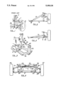
- FIG. 5 illustrates a wheel suspension linkage assembly particularly adapted to replace the conventional assembly used on many model racing cars.
- Anchor member 26 is specifically shaped and dimensioned to be attached directly to the model car infrastructure 2 and to support the mounting plate 21.
- the paritally depicted upright wheel mounting member 33 is the same as the one used on many contemporary models.
- the lower arm 34 is relatively similar to the conventional lower arm except that it does not require any connecting point for the damper.
- the upper arm 35 has been greatly simplified, and comprises the damper lever 36.
- the lever 36 is pivotally mounted on the uppermost part of the damper-mounting plate 21 which lies in substantially the same vertical plane as the lower and upper arm of the parallelogrammic linkage.
- the first radial arm 37 is pivotally connected to one end of the damper, and the second radial arm 38 engages a threaded rod 39 which forms the central part of the upper arm 35.
- the pivoting connector 40 to the upright member 33 engages the opposite end of the threaded rod 39, the adjustable length of the upper arm 35 provides a convenient way for correcting the camber of the wheel.
Landscapes
- Engineering & Computer Science (AREA)
- Mechanical Engineering (AREA)
- Toys (AREA)
- Vehicle Body Suspensions (AREA)
Abstract
In an independent wheel suspension assembly using a parallelogrammic linkage between the vehicle infrastructure and the wheel mounting member, a damper or shock absorber is mounted in a substantially horizontal position between an anchor point on the vehicle infrastructure and a levering bracket extending from the upper or lower arm of the parallelogrammic linkage. The horizontal placement of the damper lowers the overall profile of the vehicle and provides a convenient way for adjusting its elevation in relation to the wheels without affecting the damping characteristics of the suspension. The invention is particularly applicable to remotely controlled model racing cars.
Description
This invention relates to automotive vehicle suspension and steering systems, and more particularly to independent wheel suspension assemblies using a parallelogrammic linkage between the vehicle infrastructure and the wheel mounting member.
The conventional independent wheel suspension assembly of an automotive vehicle is grammatically illustrated in FIG. 1. A parallelogrammic linkage 1 is used between the infrastructure of the vehicle 2 and the upright wheel mounting member 3. The linkage 1 operates about the four pivoting points 4, 5, 6 and 7. The upper arm 8 of the linkage generally has a triangular or wishbone shape in order for provide clearance for the vertically mounted damper or shock absorber 9 connected between the lower arm 10 and an anchor point 11 in the upper part of the infrastructure 2. In a front wheel assembly, a steering arm 12 extends from the wheel mounting upright member 3 and is pivotally connected to the track rod 13. The wheel 14 mounts on the hub 15 which forms an integral part of the upright member 3 and contains the brake mechanism.
In many sport cars and racing cars where the lowest possible profile is desirable, the damper anchoring point 11 constitutes the highest point of the vehicle infrastructure. A lower profile can only be achieved by reducing the lengths of the damper to its practical limit. The minimum height of the damper attachment becomes a critically limiting parameter. The problem is compounded in self-powered and remotely controlled model racing cars due to the impossibility of making effective dampers commensurate in size with the model vehicle. Accordingly, it is now impossible to maintain a proper scale relationship between the wheel suspension assembly and the overall dimensions of the model vehicle.
The principal and secondary objects of the instant invention are to provide for a quasi-horizontal placement of the damper in an independent wheel suspension in order to reduce the overall height of the suspension assembly, and to allow for a convenient adjustment of the vehicle infrastructure elevation in relation to the axles of the wheels.
These and other objects are achieved by connecting the damper between a low point in the central part of the vehicle infrastructure and a lever extending from the upper or lower arm of the parallelogrammic linkage assembly.
FIG. 1 is a diagrammatical representation of an independent wheel suspension of the prior arts;
FIG. 2 is a diagram illustrating a first embodiment of the invention;
FIG. 3 is a diagram illustrating a second embodiment of the invention;
FIG. 4 is a front elevational view of a model car front wheel assembly according to the invention; and
FIG. 5 is a perspective view of a model car parallelogrammic wheel linkage assembly.
FIG. 2 of the drawing illustrates a first embodiment of the invention which is best understood by comparison to the structure of the prior art illustrated in FIG. 1. The wishbone member 8 which forms the upper arm of the parallelogrammic linkage has been replaced by a straight member 16. A damper mounting lever 17 extends from the upper arm 16 in a generally radial and upward direction from the pivot point 7. The damper 9 is connected between the upper end 18 of the lever 17 and one of a plurality of anchor points 19 on a centrally located lower part of the infrastructure 2. Accordingly, the elevation of the highest point of the linkage assembly, in this case the end of the lever 17, is considerably lower than the anchoring point 11 of the prior art. The elevation of the infrastructure 2 in relation to the hub 15 of the wheel can be conveniently adjusted by connecting the opposite end of the damper to one of the anchoring points 19 on the chassis or infrastructure 2.
In the second embodiment of the invention diagrammatically illustrated in FIG. 3, a damper mounting lever 19 extends in a generally upward direction from the pivoting point 4 of the lower arm 20. This configuration further reduces the overall height of the linkage assembly.
FIG. 4 offers a more comprehensive illustration of a suspension assembly particularly applicable to model racing cars. It should be noted that relatively long shock absorbers or dampers 22 and 23 are used. These dampers span almost the entire width of the vehicle without any detrimental effect on the overall height of the assembly. The multiple anchoring points 24 and 25 along the mounting plate 21 secured to the infrastructure 2 of the vehicle by anchor members 26 allows for a convenient adjustment of the height of the vehicle in relationship to the wheels 27 and 28. The angle 29 between the radial orientation of the damper lever 30 and the orientation of the upper arm 31 may vary between 70 and 110 degrees with optimum performance around 95 degrees.
FIG. 5 illustrates a wheel suspension linkage assembly particularly adapted to replace the conventional assembly used on many model racing cars. Anchor member 26 is specifically shaped and dimensioned to be attached directly to the model car infrastructure 2 and to support the mounting plate 21. The paritally depicted upright wheel mounting member 33 is the same as the one used on many contemporary models. The lower arm 34 is relatively similar to the conventional lower arm except that it does not require any connecting point for the damper. The upper arm 35 has been greatly simplified, and comprises the damper lever 36. The lever 36 is pivotally mounted on the uppermost part of the damper-mounting plate 21 which lies in substantially the same vertical plane as the lower and upper arm of the parallelogrammic linkage. The first radial arm 37 is pivotally connected to one end of the damper, and the second radial arm 38 engages a threaded rod 39 which forms the central part of the upper arm 35. The pivoting connector 40 to the upright member 33 engages the opposite end of the threaded rod 39, the adjustable length of the upper arm 35 provides a convenient way for correcting the camber of the wheel.
While the preferred embodiments of the invention have been described, modifications can be made and other embodiments can be devised without departing from the spirit of the invention and the scope of the appended claims.
Claims (12)
1. In an independent wheel suspension comprising a parallelogrammatic linkage between the wheel and the infrastructure of a vehicle, said linkage comprising a wheel-mounting member, a lower arm pivotally connected to a lower part of an upright member and to a low point of the infrastructure, a upper arm pivotally connected to a upper part of the upright member and to a high point of said infrastructure above and space-apart from said low point, and a damper connected between one of said arms and a point of said infrastructure; the improvement which comprises:
a damper-connecting lever attached to one of said arms and extending in a substantially radial direction from one of said points; and
means for mounting said damper in a substantially horizontal position between said damper-connecting lever and one of a plurality of anchor points on said infrastructure;
wherein said anchor points are located at an elevation not higher than said high points; and
wherein said damper-connecting lever is attached to the linkage upper arm.
2. The improvement of claim 1 which further comprises:
an anchor member fixedly attached to said lower point of the infrastructure, and pivotally supporting said lower arm;
a damper-mounting plate fixedly attached to said anchor member, and substantially lying in the same vertical plane as said parallelogrammic linkage;
said damper-connecting lever being pivotally mounted at said high point on said damper-mounting plate, and having a first radial arm pivotally attached to one end of the damper, and a second radial arm fixedly and axially connected to said upper arm.
3. The improvement of claim 2, wherein the first radial arm extends in a substantially vertical position from said high point.
4. The improvement of claim 3, wherein an angle between said first and second radial arms is within the range of 70 to 110 degrees.
5. The improvement of claim 4, wherein said plurality of anchor points are located on said damper-mounting plate.
6. The improvement of claim 5, wherein the upper arm comprises a length-adjustable component.
7. In an independent wheel suspension of a reduced-scale model car comprising a parallelogrammatic linkage between the wheel and the infrastructure of the car, said linkage comprising a wheel-mounting member, a lower arm pivotally connected to a lower part of an upright member and to a low point of the infrastructure, a upper arm pivotally connected to a upper part of the upright member and to a high point of said infrastructure above and spaced-apart from said low point, and a damper connected between one of said arms and a point of said infrastructure; the improvement which comprises:
a damper-connecting lever attached to one of said arms and extending in a substantially radial direction from one of said points;
means for mounting said damper in a substantially horizontal position between said damper-connecting lever and one of a plurality of anchor points on said infrastructure;
wherein said anchor points are located at an elevation not higher than said high point; and
said damper-connecting lever is attached to the linkage upper arm.
8. The improvement of claim 7 which further comprises:
an anchor member fixedly attached to said low point of the infrastructure, and pivotally supporting said lower arm;
a damper-mounting plate fixedly attached to said anchor member, and substantially lying in the same vertical plane as said parallelogrammic linkage;
said damper-connecting lever being pivotally mounted at said high point on said damper-mounting plate, and having a first radial arm pivotally attached to one end of the damper, and a second radial arm fixedly and axially connected to said upper arm.
9. The improvement of claim 8, wherein the first radial arm extends in a substantially vertical position from said high point.
10. The improvement of claim 9, wherein an angle between said first and second radial arms is within the range of 70 to 110 degrees.
11. The improvement of claim 10, wherein said plurality of anchor points are located on said damper-mounting plate.
12. The improvement of claim 11, wherein the upper arm comprises a length-adjustable component.
Priority Applications (1)
| Application Number | Priority Date | Filing Date | Title |
|---|---|---|---|
| US07/583,139 US5108126A (en) | 1990-09-17 | 1990-09-17 | Wheel suspension assembly |
Applications Claiming Priority (1)
| Application Number | Priority Date | Filing Date | Title |
|---|---|---|---|
| US07/583,139 US5108126A (en) | 1990-09-17 | 1990-09-17 | Wheel suspension assembly |
Publications (1)
| Publication Number | Publication Date |
|---|---|
| US5108126A true US5108126A (en) | 1992-04-28 |
Family
ID=24331834
Family Applications (1)
| Application Number | Title | Priority Date | Filing Date |
|---|---|---|---|
| US07/583,139 Expired - Fee Related US5108126A (en) | 1990-09-17 | 1990-09-17 | Wheel suspension assembly |
Country Status (1)
| Country | Link |
|---|---|
| US (1) | US5108126A (en) |
Cited By (56)
| Publication number | Priority date | Publication date | Assignee | Title |
|---|---|---|---|---|
| US5338247A (en) * | 1992-10-30 | 1994-08-16 | Miles Jeffrey A | Battery powered model car |
| WO1995012499A1 (en) * | 1993-11-01 | 1995-05-11 | Hyundai Motor Company | Suspension system for a vehicle |
| DE4437234A1 (en) * | 1994-10-05 | 1996-04-25 | Hyundai Motor Co Ltd | Suspension system for front wheels of bus with low coachwork |
| US5643041A (en) * | 1995-01-10 | 1997-07-01 | Nikki Co., Ltd. | Toy vehicle having adjustable load clearance |
| FR2763840A1 (en) * | 1997-05-30 | 1998-12-04 | Yves Dignat | WHEELCHAIR WITH IMPROVED SUSPENSION |
| US5921568A (en) * | 1995-10-27 | 1999-07-13 | Chrysler Corporation | Front suspension system with substantially horizontal shock absorber |
| US6604982B1 (en) | 2002-02-06 | 2003-08-12 | Linda Croteau-Brooks | Suspension device, suspension assembly including such a device, and method of use |
| US6641152B1 (en) * | 1999-08-05 | 2003-11-04 | Kabushiki Kaisha Toyoda Jidoshokki Seisakusho | Swing suppressing device for industrial vehicle |
| US20030205880A1 (en) * | 2000-01-25 | 2003-11-06 | Walker Peter John | Vehicle suspension system |
| US20040144591A1 (en) * | 2002-12-20 | 2004-07-29 | Masahiro Kuroki | Vehicular power transmission mechanism |
| US20040262876A1 (en) * | 2003-06-25 | 2004-12-30 | Hyundai Mobis Co., Ltd. | Interconnected suspension |
| US20050098975A1 (en) * | 2003-11-11 | 2005-05-12 | Hyundai Mobis Co., Ltd. | Actuator assembly for a suspension |
| US6945843B1 (en) | 2004-04-28 | 2005-09-20 | Motosko Stephen J | Toy lowrider model vehicle |
| US20060027990A1 (en) * | 2004-08-06 | 2006-02-09 | Dobson Kenneth S | Vehicle roll stabilizing damper system |
| US20060057934A1 (en) * | 2002-12-19 | 2006-03-16 | Nikko Co. Ltd | Traveling toy and suspension of traveling toy |
| US20060264151A1 (en) * | 2005-04-07 | 2006-11-23 | Traxxas | Vehicle suspension for a model vehicle |
| US20070042674A1 (en) * | 2005-01-21 | 2007-02-22 | Dr. Ing. H.C.F. Porsche Aktiengesellschaft | Rear axle of a chassis for a toy vehicle |
| US20070176386A1 (en) * | 2006-02-01 | 2007-08-02 | Schlangen Adam J | Independent rear suspension system for an all terrain vehicle |
| US20080303227A1 (en) * | 2007-06-11 | 2008-12-11 | Pak Chi Chun Idiot | Model vehicle chassis |
| US20090036021A1 (en) * | 2005-04-07 | 2009-02-05 | Brent Whitfield Byers | Rocker arm assembly for a model vehicle |
| US20120276809A1 (en) * | 2011-04-29 | 2012-11-01 | Mattel, Inc. | Toy vehicle |
| CN105252985A (en) * | 2015-09-07 | 2016-01-20 | 北京航天发射技术研究所 | Suspension mechanism, mecanum wheel suspension assembly and mecanum wheel rack car |
| US9375649B2 (en) | 2014-08-05 | 2016-06-28 | Mattel, Inc. | Toy vehicle |
| US9517673B2 (en) * | 2014-07-18 | 2016-12-13 | GM Global Technology Operations LLC | Vehicle and a suspension system for the vehicle |
| USD828460S1 (en) | 2017-01-27 | 2018-09-11 | Traxxas, LP | Shock tower for a model vehicle |
| USD839363S1 (en) | 2015-09-18 | 2019-01-29 | Traxxas Llp | Shock tower for a model vehicle |
| CN110422265A (en) * | 2019-07-29 | 2019-11-08 | 巴哈勃科技(成都)有限公司 | Shock-damping structure, vehicle head structure and slide plate |
| USD875186S1 (en) | 2018-01-10 | 2020-02-11 | Traxxas Lp | Upper front suspension arm for a model vehicle |
| USD896709S1 (en) | 2019-06-28 | 2020-09-22 | Traxxas Lp | Model vehicle shock tower |
| USD902090S1 (en) | 2019-09-10 | 2020-11-17 | Traxxas Lp | Model vehicle lower suspension arm |
| USD902089S1 (en) | 2019-09-10 | 2020-11-17 | Traxxas Llp | Model vehicle upper suspension arm |
| USD905799S1 (en) | 2019-06-27 | 2020-12-22 | Traxxas Lp | Model vehicle lower suspension arm |
| USD905798S1 (en) | 2019-06-27 | 2020-12-22 | Traxxas Lp | Model vehicle upper suspension arm |
| USD929507S1 (en) | 2019-06-27 | 2021-08-31 | Traxxas Lp | Model vehicle shock tower |
| USD930088S1 (en) | 2019-06-27 | 2021-09-07 | Traxxas Lp | Model vehicle shock tower |
| USD944901S1 (en) | 2019-12-06 | 2022-03-01 | Traxxas Lp | Model vehicle lower suspension arm |
| US11290032B1 (en) | 2021-07-22 | 2022-03-29 | Gonzalo Fuentes Iriarte | Systems and methods for electric vehicle energy recovery |
| USD947957S1 (en) | 2019-12-11 | 2022-04-05 | Traxxas Lp | Model vehicle upper suspension arm |
| USD951149S1 (en) | 2019-10-31 | 2022-05-10 | Traxxas, L.P. | Model vehicle upper suspension arm |
| USD951151S1 (en) | 2019-10-31 | 2022-05-10 | Traxxas, L.P. | Model vehicle lower suspension arm |
| USD951150S1 (en) | 2019-10-31 | 2022-05-10 | Traxxas, L.P. | Model vehicle lower suspension arm |
| USD951148S1 (en) | 2019-10-31 | 2022-05-10 | Traxxas, L.P. | Model vehicle lower suspension arm |
| USD955503S1 (en) | 2019-06-28 | 2022-06-21 | Traxxas, L.P. | Model vehicle shock tower |
| USD996529S1 (en) | 2021-11-16 | 2023-08-22 | Traxxas, L.P. | Model vehicle shock tower |
| USD998058S1 (en) | 2021-11-16 | 2023-09-05 | Traxxas, L.P. | Model vehicle shock tower |
| USD1014656S1 (en) | 2021-11-16 | 2024-02-13 | Traxxas, L.P. | Model vehicle suspension arm |
| USD1014655S1 (en) | 2021-11-16 | 2024-02-13 | Traxxas, L.P. | Model vehicle suspension arm |
| USD1023849S1 (en) | 2022-07-27 | 2024-04-23 | Traxxas, L.P. | Model vehicle shock tower |
| USD1023847S1 (en) | 2022-07-27 | 2024-04-23 | Traxxas, L.P. | Model vehicle shock tower |
| USD1026743S1 (en) | 2022-09-07 | 2024-05-14 | Traxxas, L.P. | Model vehicle shock tower |
| US20240157753A1 (en) * | 2022-11-11 | 2024-05-16 | Robert Bosch Gmbh | Roll control system and vehicle |
| USD1039066S1 (en) | 2022-07-27 | 2024-08-13 | Traxxas, L.P. | Model vehicle shock tower |
| USD1043459S1 (en) | 2022-09-07 | 2024-09-24 | Traxxas, L.P. | Model vehicle shock tower |
| USD1067835S1 (en) | 2022-07-27 | 2025-03-25 | Traxxas, L.P. | Model vehicle shock tower |
| USD1072086S1 (en) | 2023-06-15 | 2025-04-22 | Traxxas, L.P. | Model vehicle shock tower |
| USD1072085S1 (en) | 2023-06-15 | 2025-04-22 | Traxxas, L.P. | Model vehicle shock tower |
Citations (7)
| Publication number | Priority date | Publication date | Assignee | Title |
|---|---|---|---|---|
| US2580559A (en) * | 1948-03-12 | 1952-01-01 | Kolbe Joachim | Inwardly banking vehicle employing forked banking arms |
| US3326544A (en) * | 1965-03-29 | 1967-06-20 | Stuyvesant C Smith | Shock absorber for vehicles |
| DE2137757A1 (en) * | 1971-07-28 | 1973-02-08 | Parsons Jun | WHEEL SUSPENSION FOR VEHICLES |
| DE2441905A1 (en) * | 1974-09-02 | 1976-03-11 | Werner Dipl Ing Schnaebele | Suspension with compensated cornering - uses transverse linkage to alter spring supports asymmetrically due to centrifugal force |
| US4515390A (en) * | 1983-04-11 | 1985-05-07 | Greenberg William H | Chassis and suspension system for vehicles |
| US4854603A (en) * | 1988-06-24 | 1989-08-08 | Onofrio Scaduto | Constant camber suspension system |
| US4881752A (en) * | 1987-08-03 | 1989-11-21 | Honda Giken Kogyo Kabushiki Kaisha | Independent rear wheel suspension system |
-
1990
- 1990-09-17 US US07/583,139 patent/US5108126A/en not_active Expired - Fee Related
Patent Citations (7)
| Publication number | Priority date | Publication date | Assignee | Title |
|---|---|---|---|---|
| US2580559A (en) * | 1948-03-12 | 1952-01-01 | Kolbe Joachim | Inwardly banking vehicle employing forked banking arms |
| US3326544A (en) * | 1965-03-29 | 1967-06-20 | Stuyvesant C Smith | Shock absorber for vehicles |
| DE2137757A1 (en) * | 1971-07-28 | 1973-02-08 | Parsons Jun | WHEEL SUSPENSION FOR VEHICLES |
| DE2441905A1 (en) * | 1974-09-02 | 1976-03-11 | Werner Dipl Ing Schnaebele | Suspension with compensated cornering - uses transverse linkage to alter spring supports asymmetrically due to centrifugal force |
| US4515390A (en) * | 1983-04-11 | 1985-05-07 | Greenberg William H | Chassis and suspension system for vehicles |
| US4881752A (en) * | 1987-08-03 | 1989-11-21 | Honda Giken Kogyo Kabushiki Kaisha | Independent rear wheel suspension system |
| US4854603A (en) * | 1988-06-24 | 1989-08-08 | Onofrio Scaduto | Constant camber suspension system |
Cited By (73)
| Publication number | Priority date | Publication date | Assignee | Title |
|---|---|---|---|---|
| US5338247A (en) * | 1992-10-30 | 1994-08-16 | Miles Jeffrey A | Battery powered model car |
| WO1995012499A1 (en) * | 1993-11-01 | 1995-05-11 | Hyundai Motor Company | Suspension system for a vehicle |
| US5704632A (en) * | 1993-11-01 | 1998-01-06 | Hyundai Motor Company | Suspension system for a vehicle |
| DE4437234A1 (en) * | 1994-10-05 | 1996-04-25 | Hyundai Motor Co Ltd | Suspension system for front wheels of bus with low coachwork |
| US5643041A (en) * | 1995-01-10 | 1997-07-01 | Nikki Co., Ltd. | Toy vehicle having adjustable load clearance |
| US5921568A (en) * | 1995-10-27 | 1999-07-13 | Chrysler Corporation | Front suspension system with substantially horizontal shock absorber |
| WO1998053786A3 (en) * | 1997-05-30 | 1999-03-04 | Yves Dignat | Wheelchair with improved suspension |
| FR2763840A1 (en) * | 1997-05-30 | 1998-12-04 | Yves Dignat | WHEELCHAIR WITH IMPROVED SUSPENSION |
| US6412804B1 (en) | 1997-05-30 | 2002-07-02 | M. Yves Dignat | Wheelchair with improved suspension |
| US6641152B1 (en) * | 1999-08-05 | 2003-11-04 | Kabushiki Kaisha Toyoda Jidoshokki Seisakusho | Swing suppressing device for industrial vehicle |
| US20030205880A1 (en) * | 2000-01-25 | 2003-11-06 | Walker Peter John | Vehicle suspension system |
| US7407173B2 (en) * | 2000-01-25 | 2008-08-05 | Peter John Walker | Vehicle suspension system |
| US6604982B1 (en) | 2002-02-06 | 2003-08-12 | Linda Croteau-Brooks | Suspension device, suspension assembly including such a device, and method of use |
| US20060057934A1 (en) * | 2002-12-19 | 2006-03-16 | Nikko Co. Ltd | Traveling toy and suspension of traveling toy |
| US7335084B2 (en) * | 2002-12-19 | 2008-02-26 | Nikko Co., Ltd. | Traveling toy and suspension of traveling toy |
| EP1431097A3 (en) * | 2002-12-20 | 2004-09-15 | HONDA MOTOR CO., Ltd. | Vehicular power transmission mechanism |
| US20040144591A1 (en) * | 2002-12-20 | 2004-07-29 | Masahiro Kuroki | Vehicular power transmission mechanism |
| US7287621B2 (en) | 2002-12-20 | 2007-10-30 | Honda Motor Co., Ltd. | Vehicular power transmission mechanism |
| US7077407B2 (en) * | 2003-06-25 | 2006-07-18 | Hyundai Mobis Co., Ltd. | Interconnected suspension |
| US20040262876A1 (en) * | 2003-06-25 | 2004-12-30 | Hyundai Mobis Co., Ltd. | Interconnected suspension |
| US7111849B2 (en) * | 2003-11-11 | 2006-09-26 | Hyundai Mobis Co., Ltd. | Actuator assembly for a suspension |
| US20050098975A1 (en) * | 2003-11-11 | 2005-05-12 | Hyundai Mobis Co., Ltd. | Actuator assembly for a suspension |
| US6945843B1 (en) | 2004-04-28 | 2005-09-20 | Motosko Stephen J | Toy lowrider model vehicle |
| US20060027990A1 (en) * | 2004-08-06 | 2006-02-09 | Dobson Kenneth S | Vehicle roll stabilizing damper system |
| US7628414B2 (en) * | 2004-08-06 | 2009-12-08 | Illinois Tool Works Inc. | Vehicle roll stabilizing damper system |
| US20070042674A1 (en) * | 2005-01-21 | 2007-02-22 | Dr. Ing. H.C.F. Porsche Aktiengesellschaft | Rear axle of a chassis for a toy vehicle |
| US7883099B2 (en) * | 2005-04-07 | 2011-02-08 | Traxxas Lp | Vehicle suspension for a model vehicle |
| US20060264151A1 (en) * | 2005-04-07 | 2006-11-23 | Traxxas | Vehicle suspension for a model vehicle |
| US7887074B2 (en) | 2005-04-07 | 2011-02-15 | Traxxas Lp | Rocker arm assembly for a model vehicle |
| US20090036021A1 (en) * | 2005-04-07 | 2009-02-05 | Brent Whitfield Byers | Rocker arm assembly for a model vehicle |
| US20070176386A1 (en) * | 2006-02-01 | 2007-08-02 | Schlangen Adam J | Independent rear suspension system for an all terrain vehicle |
| US8585068B2 (en) * | 2006-02-01 | 2013-11-19 | Polaris Industries Inc. | Independent rear suspension system for an all terrain vehicle |
| US20080303227A1 (en) * | 2007-06-11 | 2008-12-11 | Pak Chi Chun Idiot | Model vehicle chassis |
| US20120276809A1 (en) * | 2011-04-29 | 2012-11-01 | Mattel, Inc. | Toy vehicle |
| US8764511B2 (en) * | 2011-04-29 | 2014-07-01 | Mattel, Inc. | Toy vehicle |
| US9517673B2 (en) * | 2014-07-18 | 2016-12-13 | GM Global Technology Operations LLC | Vehicle and a suspension system for the vehicle |
| US9375649B2 (en) | 2014-08-05 | 2016-06-28 | Mattel, Inc. | Toy vehicle |
| CN105252985A (en) * | 2015-09-07 | 2016-01-20 | 北京航天发射技术研究所 | Suspension mechanism, mecanum wheel suspension assembly and mecanum wheel rack car |
| CN105252985B (en) * | 2015-09-07 | 2018-02-09 | 北京航天发射技术研究所 | Suspension fork mechanism, Mecanum wheel suspended rack assembly and Mecanum wheel unwheeling |
| USD839363S1 (en) | 2015-09-18 | 2019-01-29 | Traxxas Llp | Shock tower for a model vehicle |
| USD856432S1 (en) | 2015-09-18 | 2019-08-13 | Traxxas L.P. | Shock tower for a model vehicle |
| USD828460S1 (en) | 2017-01-27 | 2018-09-11 | Traxxas, LP | Shock tower for a model vehicle |
| USD875186S1 (en) | 2018-01-10 | 2020-02-11 | Traxxas Lp | Upper front suspension arm for a model vehicle |
| USD905799S1 (en) | 2019-06-27 | 2020-12-22 | Traxxas Lp | Model vehicle lower suspension arm |
| USD905798S1 (en) | 2019-06-27 | 2020-12-22 | Traxxas Lp | Model vehicle upper suspension arm |
| USD929507S1 (en) | 2019-06-27 | 2021-08-31 | Traxxas Lp | Model vehicle shock tower |
| USD930088S1 (en) | 2019-06-27 | 2021-09-07 | Traxxas Lp | Model vehicle shock tower |
| USD896709S1 (en) | 2019-06-28 | 2020-09-22 | Traxxas Lp | Model vehicle shock tower |
| USD955503S1 (en) | 2019-06-28 | 2022-06-21 | Traxxas, L.P. | Model vehicle shock tower |
| CN110422265A (en) * | 2019-07-29 | 2019-11-08 | 巴哈勃科技(成都)有限公司 | Shock-damping structure, vehicle head structure and slide plate |
| USD902090S1 (en) | 2019-09-10 | 2020-11-17 | Traxxas Lp | Model vehicle lower suspension arm |
| USD902089S1 (en) | 2019-09-10 | 2020-11-17 | Traxxas Llp | Model vehicle upper suspension arm |
| USD951151S1 (en) | 2019-10-31 | 2022-05-10 | Traxxas, L.P. | Model vehicle lower suspension arm |
| USD951149S1 (en) | 2019-10-31 | 2022-05-10 | Traxxas, L.P. | Model vehicle upper suspension arm |
| USD951150S1 (en) | 2019-10-31 | 2022-05-10 | Traxxas, L.P. | Model vehicle lower suspension arm |
| USD951148S1 (en) | 2019-10-31 | 2022-05-10 | Traxxas, L.P. | Model vehicle lower suspension arm |
| USD944901S1 (en) | 2019-12-06 | 2022-03-01 | Traxxas Lp | Model vehicle lower suspension arm |
| USD947957S1 (en) | 2019-12-11 | 2022-04-05 | Traxxas Lp | Model vehicle upper suspension arm |
| US11290032B1 (en) | 2021-07-22 | 2022-03-29 | Gonzalo Fuentes Iriarte | Systems and methods for electric vehicle energy recovery |
| USD996529S1 (en) | 2021-11-16 | 2023-08-22 | Traxxas, L.P. | Model vehicle shock tower |
| USD998058S1 (en) | 2021-11-16 | 2023-09-05 | Traxxas, L.P. | Model vehicle shock tower |
| USD1014656S1 (en) | 2021-11-16 | 2024-02-13 | Traxxas, L.P. | Model vehicle suspension arm |
| USD1014655S1 (en) | 2021-11-16 | 2024-02-13 | Traxxas, L.P. | Model vehicle suspension arm |
| USD1023849S1 (en) | 2022-07-27 | 2024-04-23 | Traxxas, L.P. | Model vehicle shock tower |
| USD1023847S1 (en) | 2022-07-27 | 2024-04-23 | Traxxas, L.P. | Model vehicle shock tower |
| USD1039066S1 (en) | 2022-07-27 | 2024-08-13 | Traxxas, L.P. | Model vehicle shock tower |
| USD1067835S1 (en) | 2022-07-27 | 2025-03-25 | Traxxas, L.P. | Model vehicle shock tower |
| USD1026743S1 (en) | 2022-09-07 | 2024-05-14 | Traxxas, L.P. | Model vehicle shock tower |
| USD1043459S1 (en) | 2022-09-07 | 2024-09-24 | Traxxas, L.P. | Model vehicle shock tower |
| US20240157753A1 (en) * | 2022-11-11 | 2024-05-16 | Robert Bosch Gmbh | Roll control system and vehicle |
| US12194801B2 (en) * | 2022-11-11 | 2025-01-14 | Robert Bosch Gmbh | Roll control system and vehicle |
| USD1072086S1 (en) | 2023-06-15 | 2025-04-22 | Traxxas, L.P. | Model vehicle shock tower |
| USD1072085S1 (en) | 2023-06-15 | 2025-04-22 | Traxxas, L.P. | Model vehicle shock tower |
Similar Documents
| Publication | Publication Date | Title |
|---|---|---|
| US5108126A (en) | Wheel suspension assembly | |
| US4537420A (en) | Swing-arm-type suspension with a lateral rod for an automotive vehicle | |
| US7185902B1 (en) | Strut suspension with pivoting rocker arm | |
| US4614359A (en) | Vehicle wheel with height adjustment | |
| KR101072793B1 (en) | Axle Clamp Assembly Top Pad and Air Spring Mounting Assembly | |
| US7896369B2 (en) | Vehicle suspension assembly with unique geometry | |
| US10226977B2 (en) | Vehicle suspension | |
| JPH0342322A (en) | Suspension device of automobile | |
| US6086077A (en) | Steer axle suspension with air springs | |
| US5984330A (en) | Strut wheel suspension system | |
| US6997468B2 (en) | Control rod suspension with outboard shock | |
| KR0131309B1 (en) | Suspension of automobile | |
| US7077407B2 (en) | Interconnected suspension | |
| JPS6239308A (en) | Suspension system for car | |
| US4614358A (en) | Stabilizer for vehicles | |
| CN214606969U (en) | Automobile rear drive trailing arm type independent suspension structure and rear drive suspension assembly | |
| JPS6117715B2 (en) | ||
| US6431532B1 (en) | Variable geometry dampening and trailing arm suspension including same | |
| JPH08500558A (en) | Independent wheel suspension | |
| US4083575A (en) | Vehicle suspension system | |
| JPH0274408A (en) | Suspension device for vehicle | |
| KR19980040143A (en) | McPherson Independent Suspension System for Automobile | |
| US4148501A (en) | Suspension system | |
| JPH01278813A (en) | Vehicle suspension device | |
| US10639954B2 (en) | Multi-link suspension system |
Legal Events
| Date | Code | Title | Description |
|---|---|---|---|
| FEPP | Fee payment procedure |
Free format text: PAYOR NUMBER ASSIGNED (ORIGINAL EVENT CODE: ASPN); ENTITY STATUS OF PATENT OWNER: SMALL ENTITY |
|
| REMI | Maintenance fee reminder mailed | ||
| LAPS | Lapse for failure to pay maintenance fees | ||
| FP | Lapsed due to failure to pay maintenance fee |
Effective date: 19960501 |
|
| STCH | Information on status: patent discontinuation |
Free format text: PATENT EXPIRED DUE TO NONPAYMENT OF MAINTENANCE FEES UNDER 37 CFR 1.362 |