US510759A - Aerial camera - Google Patents
Aerial camera Download PDFInfo
- Publication number
- US510759A US510759A US510759DA US510759A US 510759 A US510759 A US 510759A US 510759D A US510759D A US 510759DA US 510759 A US510759 A US 510759A
- Authority
- US
- United States
- Prior art keywords
- camera
- balloon
- aerial
- chamber
- shutter
- Prior art date
- Legal status (The legal status is an assumption and is not a legal conclusion. Google has not performed a legal analysis and makes no representation as to the accuracy of the status listed.)
- Expired - Lifetime
Links
- 238000010276 construction Methods 0.000 description 5
- QSHDDOUJBYECFT-UHFFFAOYSA-N mercury Chemical compound [Hg] QSHDDOUJBYECFT-UHFFFAOYSA-N 0.000 description 4
- 229910052753 mercury Inorganic materials 0.000 description 4
- 241000612703 Augusta Species 0.000 description 1
- 230000007423 decrease Effects 0.000 description 1
- 239000013013 elastic material Substances 0.000 description 1
- 230000000153 supplemental effect Effects 0.000 description 1
Images

Classifications
-
- G—PHYSICS
- G03—PHOTOGRAPHY; CINEMATOGRAPHY; ANALOGOUS TECHNIQUES USING WAVES OTHER THAN OPTICAL WAVES; ELECTROGRAPHY; HOLOGRAPHY
- G03B—APPARATUS OR ARRANGEMENTS FOR TAKING PHOTOGRAPHS OR FOR PROJECTING OR VIEWING THEM; APPARATUS OR ARRANGEMENTS EMPLOYING ANALOGOUS TECHNIQUES USING WAVES OTHER THAN OPTICAL WAVES; ACCESSORIES THEREFOR
- G03B15/00—Special procedures for taking photographs; Apparatus therefor
Definitions
- My invention relates to balloon photography, and it refers more particularly to means for causing an automatic exposure at proper altitude, and a descent of the camera with the parachute or supporting balloon, after the exposure is made.
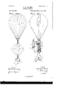
- Figure 1 is an elevation of an aerial camera, constructed in accordance with my invention.
- Fig. 2 is a similar view of a modified arrangement thereof.
- Fig. 8 is a detail view of the parachute releasing devices, and
- Fig. 4 is a diagrammatic view hereinafter particularly referred to.
- a casing E Mounted upon the camera, or secured to the camera supporting ropes a a is a casing E, in which are located the parachute releasing devices, which consist of a train of differential gears F, upon the shaft of one f of which is secured a drum G, having a radial stud or finger g.
- H indicates the parachute supporting rope, which is connected to the top of the parachute, at h, passes through the balloon ring (7, extends down through the parachute, and has its lower end h, wound about the drum G and detachably connected with the stud g as clearly shown in Fig. 8.
- the gearing F is normally held locked by means of a detent J which engages the gear f and which forms the armature bar of a magnet K.
- L indicates an aneroid barometer, located on the top of the camera, upon the face of which are located terminal points 00 y of the circuit wires :12 y which connect with the battery M, and the magnet K.
- the shutter releasing mechanism which in the present instance consists of a magnet N, adapted when energized to withdraw a detent O, which normally engages the shutter P to hold it from operation.
- the terminals as and g which are adapted to be set at any pointon the barometer be placed at two thousand feet as shown in Fig. 4, the indicator arm L would, when the camera reaches such an altitude, connect such terminals, close the electric circuit and operate the magnet N, to release the shutter detent O and allow it to momentarily pass from over the camera opening; at the same time the armature bar J would be drawn up from engagement with the gear f and as it is thus released, the weight of the parachute, the camera, and operating mechanism will pull upon the rope H and thereby cause the drum G and gears F to rotate until the end h of such rope pulls off the stud g. The parachute being thus released from the balloon, will gradually descend to the earth with the camera.
- the camera may be of any well known construction. I prefer however to incase it in a chamber R, which extends over the sides as at "r and under the bottom as at r, and such chamber is in the nature of a cushion chamber, the casing being in practice formed of some yielding or elastic material, held inflated or extended by means of air or springs.
- Fig. 2 I have shown a modified arrangement of my invention.
- the parachute is dispensed with and the operatin g mechanism and the camera connected with the balloon proper, and such balloon is constructed to lose its lifting power, immediately after the exposure is made.
- the terminal t indicates one terminal in the bottom of the chamber S,and t the otherterminal which is'adjustably held in the tube 8.
- the terminal t is first adjusted to the desired point in the tube 8. N ow as the outside air pressure decreases, it is obvious that the'interior air pressure will cause the mercury to ascend in the tube, untilit reaches the terminal t, which closes the circuit and operates to release the shutter and the gear devices Fin the manner before described.
- the balloon descends with the camera, and the operating devices.
- I form the balloon with a main gas chamber U and a central or supplemental chamber V, the
- valves V V to which is connected a valve rope o.
- the chamber U is of such a capacity that when filled with gas it will almost counterbalance or serve to lift the camera operating devices, but with thesupplemental chamber filled it will readily rise.
- Thevalve rope '0' passes down and connects with the supporting rope H and normally hangs'slack to' permit the valves V V I at the upper end of chamber V to remain closed.
- the weight of the camera will serve to unwiud'such of the rope as is coiled on the drum, and as it is drawn taut it (the rope H) Willdraw on the valve rope Hand power of the balloon sufficiently to allow for open the valves, and release the gas held in chamber V, thereby reducing the lifting its gradual descent.
- An aerial camera comprising an aerial supporting body provided with means for reducing its lifting power, a camera having an automatic shutter and suspended from said body, an electro mechanical means connected with the shutter and the means for reducing the lifting power of the said body, abarometer in the electrical circuit of the electro mechanical means and connected with the terminals thereof, and closing the circuit when the camera reaches a predetermined height, whereby the shutter will be operated and the lifting power of the supporting body reduced as and for the purposes "set forth.
- An aerial camera comprising an "aerial supporting body provided with means-for reducing its lifting power, 'a camera having an automatically operated shutter, electro mechanical means arranged intermediate the body and camera, abarome'ter'in the electrical circuit of such electromechanical means connected with -the terminals thereof and adapted to close the'circuit through its varying movement, such means arranged substantially as shown, whereby when the camera reaches a predetermined'height'they will opcrate to first release the camera shutter and then operate the lift reducing means as and for the purposes described.
- an aerial camera in combination, the aerial or supporting body, a camera suspended therefrom, having an automatically operated shutter, an electro mechanical detent arranged to normally hold the'sh'ut'ter closed, means for reducing the lifting power of the aerial body, disposedbetween the said body and the camera, and supported from such body, an electro mechanically operated detent for normally holding such me'ansfrom operation,'such means including'an electric circuit connected with such detents, and a barometer, joining the terminals of such circuit, all arranged substantially as shown and for the purposes described.
- an aerial camera in combination, a balloon having valved outlets, a gear mechanism suspended therefrom, said mechanism including the drum G and the electro mechanical detent J, a cord wound about the drum at one end, the camera suspended'from thefree end of such cord, said camera having an automatically operated shutter, the cordH connected with the aforesaid cord, and the valves of the balloon outlets, and a barometer connccting the terminals of the wires of the electro mechanical detent J, all arranged substantially as shown and described.
- An aerial camera comprising the aerial supporting body, a camera suspended therefrom having an automatically operated shut* tor, a barometer, and connections between the cuit connected with such shutter devices and I0 barometer and shutter devices, arranged to abarometerhavingadjnstableterminal points be moved into operation to release the shutfor the terminals of such circuit substantially ter when the barometer reaches a predeteras and for the purposes described.
Landscapes
- Physics & Mathematics (AREA)
- General Physics & Mathematics (AREA)
- Stereoscopic And Panoramic Photography (AREA)
Description
' (No Model.) 2 SheetsSheet 1' 0. B. ADAMS. AERIAL CAMERA.
No. 510,759. Patented Dec. 12, 1898.
/NVENTOH 6 0792616 films,
WITNESSES:
A TTOHNEYS.
(No Model.) 2 Sheets-Sheet 2.
O. B. ADAMS. AERIAL CAMERA.
No. 510,759. Patented Dec. 12, 1893.
r0 139019 50 Maw.
f7. Q. @6 14 By "no: rumomu. umoenmma cow-Amt.
wAsmNatoN. nv c UNITED STATES PATENT OFFICE.
CORNELE BERRIEN ADAMS, OF AUGUSTA, GEORGIA.
AERIAL CAM ERA.
SPEGIFIGATION forming part of Letters Patent No. 510,759, dated December 12, 1893.
Application filed February 10, 1893- Serial No. 461,798. (No model.)
To (0 whom it may concern:
Be it known that I, CORNELE BERRIEN ADAMS, residing at Augusta, in the county of Richmond and State of Georgia, have invented a new and Improved Aerial Camera, of which the following is a specification.
My invention relates to balloon photography, and it refers more particularly to means for causing an automatic exposure at proper altitude, and a descent of the camera with the parachute or supporting balloon, after the exposure is made.
The invention consists in the peculiar co mbination and novel arrangement of parts, such as will hereinafter be fully described and claimed, reference being had to the accompanying drawings, in which Figure 1 is an elevation of an aerial camera, constructed in accordance with my invention. Fig. 2 is a similar view of a modified arrangement thereof. Fig. 8 is a detail view of the parachute releasing devices, and Fig. 4 is a diagrammatic view hereinafter particularly referred to.
In the practical construction of my improved aerial camera the several parts are so arranged that they are capable of adjustment to automatically operate to release the camera shutter, to make the exposure, when such camera reaches a predetermined height, and immediately thereafter to release such camera from the lifting balloon, or cause a sufiicient amount of gas to escape from the balloon, whereby the balloon, the camera and its supporting devices will descend. This operation 1 preferably accomplish by the means best illustrated in Figs. 1 and 3 of the drawings, by reference to which it will be seen, that the camera A (which may be of any well known construction) is suspended from a parachute B, which in turn is detachably connected to the balloon proper D.
Mounted upon the camera, or secured to the camera supporting ropes a a is a casing E, in which are located the parachute releasing devices, which consist of a train of differential gears F, upon the shaft of one f of which is secured a drum G, having a radial stud or finger g.
H indicates the parachute supporting rope, which is connected to the top of the parachute, at h, passes through the balloon ring (7, extends down through the parachute, and has its lower end h, wound about the drum G and detachably connected with the stud g as clearly shown in Fig. 8.
The gearing F is normally held locked by means of a detent J which engages the gear f and which forms the armature bar of a magnet K.
L indicates an aneroid barometer, located on the top of the camera, upon the face of which are located terminal points 00 y of the circuit wires :12 y which connect with the battery M, and the magnet K.
Referring now more particularly to Fig. at of the drawings it will be noticed that in the electrical circuit is also located the shutter releasing mechanism, which in the present instance consists of a magnet N, adapted when energized to withdraw a detent O, which normally engages the shutter P to hold it from operation.
So far as described, it is manifest should the terminals as and g which are adapted to be set at any pointon the barometer be placed at two thousand feet as shown in Fig. 4, the indicator arm L would, when the camera reaches such an altitude, connect such terminals, close the electric circuit and operate the magnet N, to release the shutter detent O and allow it to momentarily pass from over the camera opening; at the same time the armature bar J would be drawn up from engagement with the gear f and as it is thus released, the weight of the parachute, the camera, and operating mechanism will pull upon the rope H and thereby cause the drum G and gears F to rotate until the end h of such rope pulls off the stud g. The parachute being thus released from the balloon, will gradually descend to the earth with the camera.
As before stated the camera may be of any well known construction. I prefer however to incase it in a chamber R, which extends over the sides as at "r and under the bottom as at r, and such chamber is in the nature of a cushion chamber, the casing being in practice formed of some yielding or elastic material, held inflated or extended by means of air or springs.
In Fig. 2 I have shown a modified arrangement of my invention. In this instance, the parachute is dispensed with and the operatin g mechanism and the camera connected with the balloon proper, and such balloon is constructed to lose its lifting power, immediately after the exposure is made.
It will be observed by reference to Fig. 2 that the casing E is supported on the balloon ropes c c and the gear devices F mounted vertioally therein, the gear f being at the lower end and provided with a drum G as before. The supporting rope H is however in this arrangement secured firmly to the said drum, at its upper end ht, while its lower end supports the camera. Such upper end, is however wound one or more times about such drum as shown. When using the latter construction, I can dispense with the aneroid barometer, and use a barometer constructed substantially as shown in such Fig. 3, which consists'of a chamber S, having a central tube 3 projected above the same and openat both ends, the lower'end extending to near the bottom of the chamber S, and immersed in the mercury T held in the bottom of such chamber 8. It should be stated, that in practice the chamber S, is filled above the'mercury with air ofordinary or surface density, and as the air contained within such'chamber equals the outside pressure, entering through the tube 8 the mercury will be held in the tube at a level with the mercuryin the'bottom of such chamber S.
tindicates one terminal in the bottom of the chamber S,and t the otherterminal which is'adjustably held in the tube 8. In operation, the terminal t is first adjusted to the desired point in the tube 8. N ow as the outside air pressure decreases, it is obvious that the'interior air pressure will cause the mercury to ascend in the tube, untilit reaches the terminal t, which closes the circuit and operates to release the shutter and the gear devices Fin the manner before described.
As 'previously'stated, in this construction the balloon descends with the camera, and the operating devices. To this end I form the balloon with a main gas chamber U and a central or supplemental chamber V, the
upper end of which is normally held closed by valves V V to which is connected a valve rope o. In practice the chamber U is of such a capacity that when filled with gas it will almost counterbalance or serve to lift the camera operating devices, but with thesupplemental chamber filled it will readily rise. Thevalve rope '0' passes down and connects with the supporting rope H and normally hangs'slack to' permit the valves V V I at the upper end of chamber V to remain closed. When however the gear mechanism F has been released, the weight of the camera will serve to unwiud'such of the rope as is coiled on the drum, and as it is drawn taut it (the rope H) Willdraw on the valve rope Hand power of the balloon sufficiently to allow for open the valves, and release the gas held in chamber V, thereby reducing the lifting its gradual descent.
ent, is-
1. An aerial camera, comprising an aerial supporting body provided with means for reducing its lifting power, a camera having an automatic shutter and suspended from said body, an electro mechanical means connected with the shutter and the means for reducing the lifting power of the said body, abarometer in the electrical circuit of the electro mechanical means and connected with the terminals thereof, and closing the circuit when the camera reaches a predetermined height, whereby the shutter will be operated and the lifting power of the supporting body reduced as and for the purposes "set forth.
2. An aerial camera, comprising an "aerial supporting body provided with means-for reducing its lifting power, 'a camera having an automatically operated shutter, electro mechanical means arranged intermediate the body and camera, abarome'ter'in the electrical circuit of such electromechanical means connected with -the terminals thereof and adapted to close the'circuit through its varying movement, such means arranged substantially as shown, whereby when the camera reaches a predetermined'height'they will opcrate to first release the camera shutter and then operate the lift reducing means as and for the purposes described.
3. In an aerial camera, in combination, the aerial or supporting body, a camera suspended therefrom, having an automatically operated shutter, an electro mechanical detent arranged to normally hold the'sh'ut'ter closed, means for reducing the lifting power of the aerial body, disposedbetween the said body and the camera, and supported from such body, an electro mechanically operated detent for normally holding such me'ansfrom operation,'such means including'an electric circuit connected with such detents, and a barometer, joining the terminals of such circuit, all arranged substantially as shown and for the purposes described.
4-. In an aerial camera, 'a camera adapted to be supported from the balloon, having a cushion chamber at its sides and bottom, substantially as and for the purpose described.
5. In an aerial camera in combination, a balloon having valved outlets, a gear mechanism suspended therefrom, said mechanism including the drum G and the electro mechanical detent J, a cord wound about the drum at one end, the camera suspended'from thefree end of such cord, said camera having an automatically operated shutter, the cordH connected with the aforesaid cord, and the valves of the balloon outlets, and a barometer connccting the terminals of the wires of the electro mechanical detent J, all arranged substantially as shown and described.
6. An aerial camera, comprising the aerial supporting body, a camera suspended therefrom having an automatically operated shut* tor, a barometer, and connections between the cuit connected with such shutter devices and I0 barometer and shutter devices, arranged to abarometerhavingadjnstableterminal points be moved into operation to release the shutfor the terminals of such circuit substantially ter when the barometer reaches a predeteras and for the purposes described.
5 mined height substantially as and for the pur- T poses described. OORLELE BERRIEN ADAMS.
7. In an aerial camera, in combination, the \Vitnesses: balloon proper, a camera having an electro SOLON O. KEMON,
mechanically operated shutter, an electric cir- AMOS XV. HART.
Publications (1)
| Publication Number | Publication Date |
|---|---|
| US510759A true US510759A (en) | 1893-12-12 |
Family
ID=2579586
Family Applications (1)
| Application Number | Title | Priority Date | Filing Date |
|---|---|---|---|
| US510759D Expired - Lifetime US510759A (en) | Aerial camera |
Country Status (1)
| Country | Link |
|---|---|
| US (1) | US510759A (en) |
Cited By (1)
| Publication number | Priority date | Publication date | Assignee | Title |
|---|---|---|---|---|
| US3303512A (en) * | 1964-12-01 | 1967-02-07 | Edward B Johnson | Apparatus for recording aircraft conditions |
-
0
- US US510759D patent/US510759A/en not_active Expired - Lifetime
Cited By (1)
| Publication number | Priority date | Publication date | Assignee | Title |
|---|---|---|---|---|
| US3303512A (en) * | 1964-12-01 | 1967-02-07 | Edward B Johnson | Apparatus for recording aircraft conditions |
Similar Documents
| Publication | Publication Date | Title |
|---|---|---|
| US510759A (en) | Aerial camera | |
| US935717A (en) | Life-buoy. | |
| US721051A (en) | Toy gas-balloon. | |
| US1151902A (en) | Submarine mine. | |
| US1043836A (en) | Parachute apparatus. | |
| US473961A (en) | Air-valve for traps and waste-pipes | |
| US967518A (en) | Automatic fire-escape. | |
| US646635A (en) | Fire-escape. | |
| US1472733A (en) | Advertising device | |
| US2932469A (en) | Balloon system | |
| US1328227A (en) | Variable-pressure acetylene-generator | |
| US1386579A (en) | Valve-operating mechanism | |
| US161680A (en) | Improvement in regulators for electrical water-raising apparatus | |
| US766238A (en) | Actuating mechanism for theatrical curtains. | |
| US398721A (en) | Joseph j | |
| US527599A (en) | ensign | |
| US1168465A (en) | Fire-escape. | |
| US148333A (en) | Improvement in apparatus for raising sunken vessels | |
| US639751A (en) | Fire-escape. | |
| US583768A (en) | Device for raising water | |
| US1262377A (en) | Amusement device. | |
| US378330A (en) | Indicator for oil-tanks | |
| US302059A (en) | townsend | |
| US705925A (en) | Apparatus for extinguishing fire in oil-tanks or the like. | |
| US1176229A (en) | Apparatus for locating and raising sunken vessels. |