US5107236A - Molded case circuit breaker trip-to-test button and auxiliary switch interface - Google Patents
Molded case circuit breaker trip-to-test button and auxiliary switch interface Download PDFInfo
- Publication number
- US5107236A US5107236A US07/649,404 US64940491A US5107236A US 5107236 A US5107236 A US 5107236A US 64940491 A US64940491 A US 64940491A US 5107236 A US5107236 A US 5107236A
- Authority
- US
- United States
- Prior art keywords
- circuit breaker
- auxiliary switch
- contacts
- operating mechanism
- recess
- Prior art date
- Legal status (The legal status is an assumption and is not a legal conclusion. Google has not performed a legal analysis and makes no representation as to the accuracy of the status listed.)
- Expired - Fee Related
Links
- 238000012360 testing method Methods 0.000 title abstract description 31
- 239000004033 plastic Substances 0.000 claims description 9
- 230000003213 activating effect Effects 0.000 claims description 3
- 238000000926 separation method Methods 0.000 claims 2
- 230000000717 retained effect Effects 0.000 claims 1
- 238000000034 method Methods 0.000 abstract description 3
- 230000006835 compression Effects 0.000 description 4
- 238000007906 compression Methods 0.000 description 4
- 239000004020 conductor Substances 0.000 description 3
- 230000000994 depressogenic effect Effects 0.000 description 2
- 239000002991 molded plastic Substances 0.000 description 2
- 230000000881 depressing effect Effects 0.000 description 1
- 238000006073 displacement reaction Methods 0.000 description 1
- 230000004907 flux Effects 0.000 description 1
- 239000000463 material Substances 0.000 description 1
- 230000000153 supplemental effect Effects 0.000 description 1
- 229920001169 thermoplastic Polymers 0.000 description 1
- 239000004416 thermosoftening plastic Substances 0.000 description 1
Images


Classifications
-
- H—ELECTRICITY
- H01—ELECTRIC ELEMENTS
- H01H—ELECTRIC SWITCHES; RELAYS; SELECTORS; EMERGENCY PROTECTIVE DEVICES
- H01H71/00—Details of the protective switches or relays covered by groups H01H73/00 - H01H83/00
- H01H71/10—Operating or release mechanisms
- H01H71/12—Automatic release mechanisms with or without manual release
- H01H71/128—Manual release or trip mechanisms, e.g. for test purposes
-
- H—ELECTRICITY
- H01—ELECTRIC ELEMENTS
- H01H—ELECTRIC SWITCHES; RELAYS; SELECTORS; EMERGENCY PROTECTIVE DEVICES
- H01H71/00—Details of the protective switches or relays covered by groups H01H73/00 - H01H83/00
- H01H71/02—Housings; Casings; Bases; Mountings
- H01H71/0207—Mounting or assembling the different parts of the circuit breaker
- H01H71/0228—Mounting or assembling the different parts of the circuit breaker having provisions for interchangeable or replaceable parts
-
- H—ELECTRICITY
- H01—ELECTRIC ELEMENTS
- H01H—ELECTRIC SWITCHES; RELAYS; SELECTORS; EMERGENCY PROTECTIVE DEVICES
- H01H71/00—Details of the protective switches or relays covered by groups H01H73/00 - H01H83/00
- H01H71/10—Operating or release mechanisms
- H01H71/12—Automatic release mechanisms with or without manual release
- H01H71/46—Automatic release mechanisms with or without manual release having means for operating auxiliary contacts additional to the main contacts
- H01H71/465—Self-contained, easily replaceable microswitches
Definitions
- the operating mechanism assembly includes a pair of operating springs that are overcentered for rapidly driving the movable contact arm and the attached movable contact away from the stationary fixed contact to interrupt the circuit current.
- the operating mechanism includes a cradle operator which engages a latch assembly to prevent the movable contact arm from being driven to its open position under the urgence of the charged operating springs.
- the compact latch assembly includes a primary and secondary latch operating within a common support structure.
- auxiliary switch device such as described in U.S. Pat. No. 4,831,221 entitled "Molded Case Circuit Breaker Auxiliary Switch Unit" is used with molded case circuit breakers to provide remote indication of the ON-OFF conditions of the circuit breaker contacts. It would be economically advantageous if a single-sized auxiliary switch could be employed over a wide range of circuit breakers having differing ampere ratings.
- one purpose of the instant invention is to provide a trip-to-test button that can be installed within an automated circuit breaker assembly process.
- a further purpose of the invention is to provide a unit for interfacing between an auxiliary switch accessory unit and the circuit breaker operating mechanism to allow a single auxiliary switch design to be operable over a wide range of circuit breaker ratings.
- the invention comprises a trip-to-test button formed in a unitary plastic assembly with a bifurcated central post that snappingly engages a corresponding aperture formed within a circuit breaker cover to retain the button against the bias of a return spring arranged about the post.
- An auxiliary switch interface unit is positioned between an auxiliary switch accessory and the circuit breaker operating mechanism to operate the auxiliary switch when the circuit breaker contacts are moved between their ON and OFF positions.
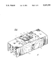
- FIG. 1 is a top perspective view of a circuit breaker employing the trip-to-test button and auxiliary switch interface unit in accordance with the invention
- FIG. 2 is a top perspective view of the circuit breaker of FIG. 1 prior to assembly of the accessory cover and accessory components;
- FIG. 3 is an enlarged top perspective view of the trip-to-test button according to the invention.
- FIG. 4A is an enlarged cutaway side view of the circuit breaker of FIG. 1 depicting the trip-to-test button in a non-operative state;
- FIG. 4B is an enlarged cutaway side view of the circuit breaker of FIG. 1 depicting the trip-to-test button in an operative state;
- FIG. 5 is an enlarged top perspective view of the auxiliary switch interface unit according to the invention.
- FIG. 6A is an enlarged cutaway side view in partial section of the circuit breaker of FIG. 1 depicting the auxiliary switch in an inactive position;
- FIG. 6B is an enlarged cutaway side view in partial section of the circuit breaker of FIG. 1 depicting the auxiliary switch in an active position.
- An electronic trip circuit breaker 10 hereafter “circuit breaker”, is depicted in FIG. 1 and consists of a molded plastic case 11 to which a molded plastic cover 12 is fixedly secured.
- An accessory cover 13 is attached to the circuit interrupter cover and provides access to an electronic trip unit 14, an actuator-accessory unit 15 and an optional accessory unit such as the auxiliary switch unit depicted at 16.
- An operating handle 17 extends through the circuit interrupter cover and provides manual intervention to turn the circuit interrupter contacts 8, 9 between their open and closed positions.
- a rating plug 14A electrically communicates with the electronic trip unit to set the ampere rating of the circuit breaker.
- a trip-to-test button 7 is installed within the circuit breaker cover to manually articulate the circuit breaker operating mechanism (not shown) and to separate the circuit breaker contacts by rotation of the operating mechanism crossbar 6.
- a pair of accessory doors 18, 19 are formed in the accessory cover for providing access to the actuator-accessory unit 15 and auxiliary switch 16, shown in the circuit breaker 10 depicted in FIG. 2.
- the rating plug 14A is fitted within a recess 20 formed in the accessory cover and the accessory cover is fastened to the circuit breaker cover by means of screws 21.
- the actuator-accessory unit 15 contains a flux shifter coil (not shown) and is fitted with an actuator lever 22 for interrupting the circuit breaker operating mechanism.
- the actuator-accessory unit 15 is fitted within a recess 23 and connects with the electronic trip unit 14 by means of wire conductors 24 and with an external shunt trip switch by means of wire conductors 25.
- the electronic trip unit 14 is inserted in the electronic trip unit recess 26 formed in the circuit breaker cover 12 and connects electrically with the rating plug 14A by means of connector pins 27 upstanding on the electronic trip unit and sockets 28 formed in the bottom of the rating plug.
- the rating plug is described in U.S. Pat. No. 4,728,914 which Patent is incorporated herein for purposes of reference. Access opening 29 formed on the top of the rating plug allows for verifying the trip characteristics of the electronic trip unit.
- the electronic trip unit electrically connects with a current transformer (not shown) contained within the circuit breaker case 11 and which is described in U.S. Pat. No. 4,591,942 which Patent is incorporated herein for purposes of reference.
- the circuit breaker includes three poles, with one current transformer supplied within each separate pole.
- the auxiliary switch unit 16 is inserted within the recess 30 formed in the circuit breaker cover and is positioned such that a depending lever 69 interacts with the circuit breaker operating mechanism in a manner to be described below in greater detail.
- a pair of wire conductors 32 electrically connect to a remote bell or alarm to indicate the closed or open condition of the circuit breaker contacts.
- access to the actuator-accessory unit 15 is made by means of accessory door 18 which is integrally-formed within the accessory cover 13 and access to the auxiliary switch 16 made by means of the corresponding accessory door 19. This arrangement differs from those described in U.S. Pat. Nos.
- test button is inserted within the recess 34 formed within the circuit breaker cover 12 next to the operating handle 17. The function of the test button is best seen by referring now to FIGS. 3, 4A, 4B.
- the test button 7 is formed from a thermoplastic composition into a unitary body 35 upon which is positioned a top disc 36 with the trip indicia 37 integrally-formed therein.
- the plastic mold used to form the body 35 is a two-part mold and is shaped such that the trip indicia 37 extends along the mold parting line as indicated in phantom at 37A. This arrangement eliminates the requirement of supplemental mold equipment and thereby realizes a substantial savings in such mold equipment costs.
- a middle disc 38 is formed under the top disc and is joined to a semi-circular planar shelf 39.
- the top disc 36 provides digital access to an operator for driving the test button into direct contact with the circuit breaker operating mechanism trip bar 51 (FIG. 4A).
- top and middle discs 36, 38 increases the oversurface electrical clearance between the operator and the electrified operating mechanism trip bar due to the increased surface distance provided by the intervening slots 36A and 38A defined between the top and middle discs and between the middle disc and the semi-circular shelf 39.
- the downwardly depending side arm 40 with the cam-shaped radial surface 41 contacts the operating mechanism trip bar and drives the trip bar along the cam-shaped surface to articulate the circuit breaker operating mechanism to rapidly separate the circuit breaker contacts.
- the bifurcated post 42 depending from the semi-circular shelf 39 positions and retains the test button within the circuit breaker cover by means of the post parts 42A, 42B separated by the elongated slot 43.
- the provision of the elongated slot allows the separated parts 42A, 42B to become pressed together and resiliently returned to the rest position shown in FIG. 3.
- a corresponding pair of elongated projections 44A, 44B then trap the test button within the trip-to-test button recess 34 in the manner best seen by referring now to FIGS. 3, 4A, 4B.
- the recess 34 is formed within the cover 12 of the circuit breaker 10 and defines a large cavity 46 and a subjacent small cavity 47 as indicated.
- the compression spring 45 arranged around the bifurcated post stops against the bottom 50 of the large cavity 46 and the bifurcated post 42 extends down through slot 48 to within the small cavity 47 whereupon the angulated projections expand within the small cavity as indicated at 44A thereby preventing removal of the test button from the test button recess.
- the compression spring 45 around the bifurcated post 42 automatically centers the bifurcated post within the large cavity 46 and the small cavity 47 to allow the bifurcated post to travel concentrically within both the large cavity and small cavity when the top disc 36 is depressed and released.
- the downwardly depending side arm 40 abuts the operating mechanism trip bar 51 when the circuit breaker contacts are in their closed condition and the operating handle 17 is in the ON position shown in FIG. 4A and stops against the top surface 49 of the large cavity 46 when the top disc 36 is depressed.
- Depressing the top disc 36 drives the downwardly depending side arm 40 and cam-shaped radial surface 41 into contact with the trip bar 51 to articulate the circuit breaker operating mechanism and separate the circuit breaker contacts.
- the operating handle 17 immediately transfers to its "TRIPPED" position as depicted in FIG. 4B.
- the bifurcated post 42 descends down within the small cavity 47 while the compression spring 45 moves down within the large cavity 46 until the semi-circular shelf 39 stops against the top surface 49 of the large cavity 46.
- the trip test button and top disc 36 immediately return to the rest position shown earlier in FIG. 4A under the emergence of the charged compression spring 45.
- the angulated projections as indicated at 44A in FIG.
- the auxiliary switch interface unit 52 hereafter “interface unit” depicted in FIG. 5 is inserted within the circuit breaker case intermediate the circuit breaker operating mechanism and the auxiliary switch.
- the interface unit 52 includes a unitary plastic body 53 having material-saving slots 54 and 55 integrally-formed therein to provide lightness and flexibility to the unitary plastic body at a substantial savings of plastic material.
- a bifurcated post 60 having two parts 60A, 60B separated by an elongated slot 61 stands upright from a platform 58 extending between a pair of rails 56, 57.
- a pair of angulated projections 62A, 62B are formed at the ends of the post parts to retain the auxiliary switch interface unit within the circuit breaker cover in a manner similar to that described earlier with reference to the trip-to-test button 7 of FIG. 3.
- the downwardly sloping surface 59 formed at one end of the platform 58 receives the bottom lever 69 of the actuator lever 67 shown within the circuit breaker 10 of FIGS. 6A and 6B.
- the interface unit 52 is fitted within the adapter recess 72 within the circuit breaker case by inserting the bifurcated post 60 through an aperture 71 formed in the floor 70 of the auxiliary switch recess 30 in the circuit breaker cover 12.
- the angulated projections one of which is indicated at 62A prevent the interface unit from becoming removed from the adapter recess in a manner similar to that described earlier for the test button 7 shown in FIG. 3.
- the auxiliary switch 16 as described earlier with reference to U.S. Pat. No. 4,831,221 includes a microswitch 64 mounted within the auxiliary switch recess and containing a switch button 65.
- the actuator lever 67 includes a top lever 68 which rotates within the auxiliary switch recess 30 along with the bottom lever 69 which rotates within the adapter recess 72.
- the actuator lever is biased into contact with the switch button 65 by means of an expansion spring 66.
- the top lever 68 is held away from the switch button 65 by contact between the projection 63 on the operating mechanism crossbar 6 (FIG. 1) and the bottom of the interface unit body 53 in concert with the contact between the bottom lever 69 and the downwardly sloped surface 59 of the platform 58. With the operating handle 17 in the OFF position indicated in FIG. 6A, the interface unit 52 accordingly prevents top lever 68 of the actuator lever 67 from rotating into contact with the switch button 65.
- the bottom lever 69 has driven the interface unit body 53 downward within the interface unit recess 72 and is prevented from falling out from the recess by means of the angulated projections as described earlier.
- the projection 63 on the operating mechanism crossbar contacts the interface unit body 53 driving the interface adapter unit 52 back to the OFF condition depicted earlier in FIG. 6A.
Landscapes
- Breakers (AREA)
Abstract
An electronic trip molded case circuit breaker includes components that are designed for high speed robotic assembly. A unitary trip-to-test button is down-loaded within the circuit breaker housing for automatic alignment with the circuit breaker operating mechanism during the circuit breaker assembly process. A unitary auxiliary switch interface unit is also down-loaded within the housing for automatic alignment with the operating mechanism during the assembly process.
Description
This is a divisional of application Ser. No. 07/553,464 filed July 16, 1990.
Industrial-rated circuit breakers are currently available having operating components that are designed for automatic assembly to provide cost improvement as well as improved operating efficiency. The precision alignment performed by the automated assembly equipment assembles the operating components within very close operating tolerances. An operating mechanism designed for down-loaded automated assembly is described in U.S. Pat. No. 4,864,263, which Patent is incorporated herein for reference purposes. The operating mechanism assembly includes a pair of operating springs that are overcentered for rapidly driving the movable contact arm and the attached movable contact away from the stationary fixed contact to interrupt the circuit current. The operating mechanism includes a cradle operator which engages a latch assembly to prevent the movable contact arm from being driven to its open position under the urgence of the charged operating springs. The compact latch assembly includes a primary and secondary latch operating within a common support structure.
U.S. Pat. No. 3,671,890 entitled "Manually Operable Molded Case Circuit Breaker With Special Trip Testing Means" and U.S. Pat. Application Ser. No. 486,681 filed Mar. 1, 1990 entitled "Rotatable Trip Test Assembly for Molded Case Circuit Breakers" both describe a trip-to-test button that allows the circuit breaker operating mechanism to be manually articulated for test purposes. In some applications, it is more advantageous to articulate the operating mechanism by linear displacement of the trip-to-test button shaft rather than by rotation.
An auxiliary switch device such as described in U.S. Pat. No. 4,831,221 entitled "Molded Case Circuit Breaker Auxiliary Switch Unit" is used with molded case circuit breakers to provide remote indication of the ON-OFF conditions of the circuit breaker contacts. It would be economically advantageous if a single-sized auxiliary switch could be employed over a wide range of circuit breakers having differing ampere ratings.
Accordingly one purpose of the instant invention is to provide a trip-to-test button that can be installed within an automated circuit breaker assembly process.
A further purpose of the invention is to provide a unit for interfacing between an auxiliary switch accessory unit and the circuit breaker operating mechanism to allow a single auxiliary switch design to be operable over a wide range of circuit breaker ratings.
The invention comprises a trip-to-test button formed in a unitary plastic assembly with a bifurcated central post that snappingly engages a corresponding aperture formed within a circuit breaker cover to retain the button against the bias of a return spring arranged about the post. An auxiliary switch interface unit is positioned between an auxiliary switch accessory and the circuit breaker operating mechanism to operate the auxiliary switch when the circuit breaker contacts are moved between their ON and OFF positions.
FIG. 1 is a top perspective view of a circuit breaker employing the trip-to-test button and auxiliary switch interface unit in accordance with the invention;
FIG. 2 is a top perspective view of the circuit breaker of FIG. 1 prior to assembly of the accessory cover and accessory components;
FIG. 3 is an enlarged top perspective view of the trip-to-test button according to the invention;
FIG. 4A is an enlarged cutaway side view of the circuit breaker of FIG. 1 depicting the trip-to-test button in a non-operative state;
FIG. 4B is an enlarged cutaway side view of the circuit breaker of FIG. 1 depicting the trip-to-test button in an operative state;
FIG. 5 is an enlarged top perspective view of the auxiliary switch interface unit according to the invention;
FIG. 6A is an enlarged cutaway side view in partial section of the circuit breaker of FIG. 1 depicting the auxiliary switch in an inactive position; and
FIG. 6B is an enlarged cutaway side view in partial section of the circuit breaker of FIG. 1 depicting the auxiliary switch in an active position.
An electronic trip circuit breaker 10 hereafter "circuit breaker", is depicted in FIG. 1 and consists of a molded plastic case 11 to which a molded plastic cover 12 is fixedly secured. An accessory cover 13 is attached to the circuit interrupter cover and provides access to an electronic trip unit 14, an actuator-accessory unit 15 and an optional accessory unit such as the auxiliary switch unit depicted at 16. An operating handle 17 extends through the circuit interrupter cover and provides manual intervention to turn the circuit interrupter contacts 8, 9 between their open and closed positions. A rating plug 14A electrically communicates with the electronic trip unit to set the ampere rating of the circuit breaker. A trip-to-test button 7 is installed within the circuit breaker cover to manually articulate the circuit breaker operating mechanism (not shown) and to separate the circuit breaker contacts by rotation of the operating mechanism crossbar 6.
A pair of accessory doors 18, 19 are formed in the accessory cover for providing access to the actuator-accessory unit 15 and auxiliary switch 16, shown in the circuit breaker 10 depicted in FIG. 2. The rating plug 14A is fitted within a recess 20 formed in the accessory cover and the accessory cover is fastened to the circuit breaker cover by means of screws 21. Still referring to FIG. 2, the actuator-accessory unit 15 contains a flux shifter coil (not shown) and is fitted with an actuator lever 22 for interrupting the circuit breaker operating mechanism. The actuator-accessory unit 15 is fitted within a recess 23 and connects with the electronic trip unit 14 by means of wire conductors 24 and with an external shunt trip switch by means of wire conductors 25. The electronic trip unit 14 is inserted in the electronic trip unit recess 26 formed in the circuit breaker cover 12 and connects electrically with the rating plug 14A by means of connector pins 27 upstanding on the electronic trip unit and sockets 28 formed in the bottom of the rating plug. The rating plug is described in U.S. Pat. No. 4,728,914 which Patent is incorporated herein for purposes of reference. Access opening 29 formed on the top of the rating plug allows for verifying the trip characteristics of the electronic trip unit. The electronic trip unit electrically connects with a current transformer (not shown) contained within the circuit breaker case 11 and which is described in U.S. Pat. No. 4,591,942 which Patent is incorporated herein for purposes of reference. The circuit breaker includes three poles, with one current transformer supplied within each separate pole. In accordance with the instant invention, the auxiliary switch unit 16 is inserted within the recess 30 formed in the circuit breaker cover and is positioned such that a depending lever 69 interacts with the circuit breaker operating mechanism in a manner to be described below in greater detail. A pair of wire conductors 32 electrically connect to a remote bell or alarm to indicate the closed or open condition of the circuit breaker contacts. In the particular arrangement depicted in FIG. 2, access to the actuator-accessory unit 15 is made by means of accessory door 18 which is integrally-formed within the accessory cover 13 and access to the auxiliary switch 16 made by means of the corresponding accessory door 19. This arrangement differs from those described in U.S. Pat. Nos. 4,794,356 and 4,788,621 which Patents are incorporated herein for purposes of reference. The accessory doors 18, 19 are hingeably attached to the accessory cover 13 by means of a hinge 33 integrally-formed therein. A good description of the accessory cover 13 is found within U.S. Pat. No. 4,754,247 which Patent is incorporated herein for reference purposes. In further accordance with the invention, the trip-to-test button 7 hereafter "test button" is inserted within the recess 34 formed within the circuit breaker cover 12 next to the operating handle 17. The function of the test button is best seen by referring now to FIGS. 3, 4A, 4B.
As shown in FIG. 3, the test button 7 is formed from a thermoplastic composition into a unitary body 35 upon which is positioned a top disc 36 with the trip indicia 37 integrally-formed therein. The plastic mold used to form the body 35 is a two-part mold and is shaped such that the trip indicia 37 extends along the mold parting line as indicated in phantom at 37A. This arrangement eliminates the requirement of supplemental mold equipment and thereby realizes a substantial savings in such mold equipment costs. A middle disc 38 is formed under the top disc and is joined to a semi-circular planar shelf 39. The top disc 36 provides digital access to an operator for driving the test button into direct contact with the circuit breaker operating mechanism trip bar 51 (FIG. 4A). The provision of the top and middle discs 36, 38 increases the oversurface electrical clearance between the operator and the electrified operating mechanism trip bar due to the increased surface distance provided by the intervening slots 36A and 38A defined between the top and middle discs and between the middle disc and the semi-circular shelf 39. The downwardly depending side arm 40 with the cam-shaped radial surface 41 contacts the operating mechanism trip bar and drives the trip bar along the cam-shaped surface to articulate the circuit breaker operating mechanism to rapidly separate the circuit breaker contacts. The bifurcated post 42 depending from the semi-circular shelf 39 positions and retains the test button within the circuit breaker cover by means of the post parts 42A, 42B separated by the elongated slot 43. The provision of the elongated slot allows the separated parts 42A, 42B to become pressed together and resiliently returned to the rest position shown in FIG. 3. A corresponding pair of elongated projections 44A, 44B then trap the test button within the trip-to-test button recess 34 in the manner best seen by referring now to FIGS. 3, 4A, 4B. The recess 34 is formed within the cover 12 of the circuit breaker 10 and defines a large cavity 46 and a subjacent small cavity 47 as indicated. When the test button 7 is inserted within the trip-to-test button recess 34 the compression spring 45 arranged around the bifurcated post stops against the bottom 50 of the large cavity 46 and the bifurcated post 42 extends down through slot 48 to within the small cavity 47 whereupon the angulated projections expand within the small cavity as indicated at 44A thereby preventing removal of the test button from the test button recess. The compression spring 45 around the bifurcated post 42 automatically centers the bifurcated post within the large cavity 46 and the small cavity 47 to allow the bifurcated post to travel concentrically within both the large cavity and small cavity when the top disc 36 is depressed and released. The downwardly depending side arm 40 abuts the operating mechanism trip bar 51 when the circuit breaker contacts are in their closed condition and the operating handle 17 is in the ON position shown in FIG. 4A and stops against the top surface 49 of the large cavity 46 when the top disc 36 is depressed.
Depressing the top disc 36 drives the downwardly depending side arm 40 and cam-shaped radial surface 41 into contact with the trip bar 51 to articulate the circuit breaker operating mechanism and separate the circuit breaker contacts. The operating handle 17 immediately transfers to its "TRIPPED" position as depicted in FIG. 4B. The bifurcated post 42 descends down within the small cavity 47 while the compression spring 45 moves down within the large cavity 46 until the semi-circular shelf 39 stops against the top surface 49 of the large cavity 46. When released, the trip test button and top disc 36 immediately return to the rest position shown earlier in FIG. 4A under the urgence of the charged compression spring 45. The angulated projections as indicated at 44A in FIG. 4A stop against the bottom of the juncture 47A defined between the large cavity 46 and the small cavity 47 and the trip bar rides downwardly along the radial surface 41 of the sidearm 40 to the position shown in FIG. 4A. It is thus seen that the cooperation between the trip-to-test button configuration and the corresponding structure provided within the circuit breaker cover accurately positions the test button, centers it, prevents its removal from the cover as well as preventing its complete dissent to the interior of the circuit breaker enclosure.
In order to employ a single auxiliary switch 16 (FIG. 2) over a wide range of circuit breaker ratings, the auxiliary switch interface unit 52 hereafter "interface unit" depicted in FIG. 5 is inserted within the circuit breaker case intermediate the circuit breaker operating mechanism and the auxiliary switch. The interface unit 52 includes a unitary plastic body 53 having material-saving slots 54 and 55 integrally-formed therein to provide lightness and flexibility to the unitary plastic body at a substantial savings of plastic material. A bifurcated post 60 having two parts 60A, 60B separated by an elongated slot 61 stands upright from a platform 58 extending between a pair of rails 56, 57. A pair of angulated projections 62A, 62B are formed at the ends of the post parts to retain the auxiliary switch interface unit within the circuit breaker cover in a manner similar to that described earlier with reference to the trip-to-test button 7 of FIG. 3. The downwardly sloping surface 59 formed at one end of the platform 58 receives the bottom lever 69 of the actuator lever 67 shown within the circuit breaker 10 of FIGS. 6A and 6B. The interface unit 52 is fitted within the adapter recess 72 within the circuit breaker case by inserting the bifurcated post 60 through an aperture 71 formed in the floor 70 of the auxiliary switch recess 30 in the circuit breaker cover 12. The angulated projections one of which is indicated at 62A prevent the interface unit from becoming removed from the adapter recess in a manner similar to that described earlier for the test button 7 shown in FIG. 3. The auxiliary switch 16 as described earlier with reference to U.S. Pat. No. 4,831,221 includes a microswitch 64 mounted within the auxiliary switch recess and containing a switch button 65. The actuator lever 67 includes a top lever 68 which rotates within the auxiliary switch recess 30 along with the bottom lever 69 which rotates within the adapter recess 72. The actuator lever is biased into contact with the switch button 65 by means of an expansion spring 66. The top lever 68 is held away from the switch button 65 by contact between the projection 63 on the operating mechanism crossbar 6 (FIG. 1) and the bottom of the interface unit body 53 in concert with the contact between the bottom lever 69 and the downwardly sloped surface 59 of the platform 58. With the operating handle 17 in the OFF position indicated in FIG. 6A, the interface unit 52 accordingly prevents top lever 68 of the actuator lever 67 from rotating into contact with the switch button 65.
With the operating handle 17 on the circuit breaker 10 in FIG. 6B in the "ON" position, it is noted that the projection 63 on the crossbar is away from the bottom of the body 53 of the interface unit 52 and the angulated projections at the end of the bifurcated post 60 rest against the floor 70 of the auxiliary switch recess 30. The actuator lever 67 is rotated under the urgence of the expansion spring 66 in the counterclockwise direction, as viewed in FIG. 6B, to drive the top lever 68 into contact with the switch button 65 thereby activating the microswitch 64 to provide remote indication that the circuit breaker is in its ON condition. The bottom lever 69 has driven the interface unit body 53 downward within the interface unit recess 72 and is prevented from falling out from the recess by means of the angulated projections as described earlier. In the event that the circuit breaker handle is now turned to the OFF position, the projection 63 on the operating mechanism crossbar contacts the interface unit body 53 driving the interface adapter unit 52 back to the OFF condition depicted earlier in FIG. 6A.
Claims (14)
1. A circuit breaker comprising:
a plastic circuit breaker case and a plastic circuit breaker cover;
a pair of contacts within said circuit breaker case arranged for automatic separation by means of an operating mechanism;
an operating handle extending through said circuit breaker cover for manually turning said contacts between open and closed conditions;
a trip unit within said circuit breaker cover determining overcurrent conditions through a protected circuit and activating said operating mechanism to separate said contacts and interrupt circuit current;
an auxiliary switch within a recess in said circuit breaker cover adjacent said operating handle providing remote indication of said open and closed conditions of said contacts; and
an interface unit having means for engaging an aperture within a bottom of said recess intermediate said auxiliary switch and said operating mechanism, said interface unit interacting with said auxiliary switch and said operating mechanism to activate and deactivate said auxiliary switch.
2. A circuit breaker comprising:
a plastic circuit breaker case and a plastic circuit breaker cover;
a pair of contacts within said circuit breaker case arranged for automatic separation by means of an operating mechanism;
an operating handle extending through said circuit breaker cover for manually turning said contacts between open and closed conditions;
a trip unit within said circuit breaker cover determining overcurrent conditions through a protected circuit and activating said operating mechanism to separate said contacts and interrupt circuit current;
an auxiliary switch within said circuit breaker cover adjacent said operating handle providing remote indication of said open and closed conditions of said contacts;
an interface unit intermediate said auxiliary switch and said operating mechanism, said interface unit interacting with said auxiliary switch and said operating mechanism to activate and deactivate said auxiliary switch;
a recess formed within said circuit breaker cover, said auxiliary switch being arranged within said recess; and
an actuator lever pivotally arranged between said auxiliary switch and said interface unit.
3. The circuit breaker of claim 1 wherein said interface unit comprises a unitary body including an upstanding bifurcated post.
4. The circuit breaker of claim 3 including a planar shelf arranged on a top surface of said body.
5. The circuit breaker of claim 3 wherein said bifurcated post includes two parts separated by an elongated slot.
6. The circuit breaker of claim 5 wherein said parts each terminate at an angulated projection.
7. The circuit breaker of claim 6 wherein said interface unit is positioned within said cavity.
8. The circuit breaker of claim 7 wherein said actuator lever comprises a top lever extending within said recess, a bottom lever extending within said cavity and a return spring arranged intermediate said top and bottom levers.
9. The circuit breaker of claim 6 wherein said bifurcated post extends within said recess.
10. The circuit breaker of claim 9 wherein said bifurcated post is retained within said cavity by trapping said angulated projections within said recess.
11. The circuit breaker of claim 8 wherein said auxiliary switch includes a microswitch arranged within said recess.
12. The circuit breaker of claim 11 wherein said top lever extends within said recess proximate said microswitch.
13. The circuit breaker of claim 12 further including a projection extending from a part of said operating mechanism proximate a bottom part of said body whereby said projection contacts said bottom part and drives said body upwards within said cavity and contacts said bottom lever thereby rotating said top lever away from said microswitch against a return bias provided by said return spring when said contacts are open.
14. The circuit breaker of claim 13 whereby said projection moves away from said body to thereby allow said return spring to drive said upper lever into contact with said microswitch when said contacts are closed.
Priority Applications (1)
| Application Number | Priority Date | Filing Date | Title |
|---|---|---|---|
| US07/649,404 US5107236A (en) | 1990-07-16 | 1991-02-01 | Molded case circuit breaker trip-to-test button and auxiliary switch interface |
Applications Claiming Priority (2)
| Application Number | Priority Date | Filing Date | Title |
|---|---|---|---|
| US07/553,464 US5075658A (en) | 1990-07-16 | 1990-07-16 | Molded case circuit breaker trip-to-test button and auxiliary switch interface |
| US07/649,404 US5107236A (en) | 1990-07-16 | 1991-02-01 | Molded case circuit breaker trip-to-test button and auxiliary switch interface |
Related Parent Applications (1)
| Application Number | Title | Priority Date | Filing Date |
|---|---|---|---|
| US07/553,464 Division US5075658A (en) | 1990-07-16 | 1990-07-16 | Molded case circuit breaker trip-to-test button and auxiliary switch interface |
Publications (1)
| Publication Number | Publication Date |
|---|---|
| US5107236A true US5107236A (en) | 1992-04-21 |
Family
ID=27070352
Family Applications (1)
| Application Number | Title | Priority Date | Filing Date |
|---|---|---|---|
| US07/649,404 Expired - Fee Related US5107236A (en) | 1990-07-16 | 1991-02-01 | Molded case circuit breaker trip-to-test button and auxiliary switch interface |
Country Status (1)
| Country | Link |
|---|---|
| US (1) | US5107236A (en) |
Cited By (20)
| Publication number | Priority date | Publication date | Assignee | Title |
|---|---|---|---|---|
| US5875885A (en) * | 1997-05-28 | 1999-03-02 | Eaton Corporation | Combined wire lead and interphase barrier for power switches |
| US6060674A (en) * | 1997-05-28 | 2000-05-09 | Eaton Corporation | Circuit interrupter with plasma arc acceleration chamber and contact arm housing |
| US6104265A (en) * | 1998-02-19 | 2000-08-15 | Eaton Corporation | Miniature circuit breaker with multipurpose auxiliary member |
| US6188302B1 (en) * | 1999-08-30 | 2001-02-13 | Eaton Corporation | Circuit breaker with two piece bell accessory lever with overtravel |
| US6239395B1 (en) * | 1999-10-14 | 2001-05-29 | General Electric Company | Auxiliary position switch assembly for a circuit breaker |
| US6472965B2 (en) * | 1999-11-05 | 2002-10-29 | Siemens Energy & Automation, Inc. | Molded case circuit breaker accessory system |
| US6498310B1 (en) * | 2001-07-19 | 2002-12-24 | Carling Technologies, Inc. | Reverse alarm switch circuit breaker |
| US6545479B1 (en) | 1999-11-05 | 2003-04-08 | Siemens Energy & Automation, Inc. | Portable tester for electronic circuit breaker |
| US6559745B2 (en) * | 2000-09-04 | 2003-05-06 | Fuji Electric Co., Ltd. | Circuit breaker, and accessory switches thereof |
| WO2005069334A1 (en) * | 2004-01-19 | 2005-07-28 | Abb Oy | Auxiliary contact configuration for switching device |
| US20070194869A1 (en) * | 2006-02-23 | 2007-08-23 | Siemens Energy & Automation, Inc. | Integrated maglatch accessory |
| EP1684320A3 (en) * | 2005-01-25 | 2007-10-17 | EATON Corporation | Reverse-action auxiliary switch actuator mechanism and circuit breaker employing the same |
| US20080237192A1 (en) * | 2007-03-28 | 2008-10-02 | Whitaker Thomas A | Electrical switching apparatus and accessory tray therefor |
| CN101436493B (en) * | 2008-12-05 | 2011-01-12 | 常熟开关制造有限公司(原常熟开关厂) | Auxiliary switch for circuit breaker |
| CN102308355A (en) * | 2009-02-05 | 2012-01-04 | 西门子公司 | Tripping apparatus, particularly for circuit breakers |
| US20120312675A1 (en) * | 2011-06-09 | 2012-12-13 | Siemens Aktiengesellschaft | Auxiliary switch for an electrical switch |
| CN110375981A (en) * | 2019-09-02 | 2019-10-25 | 云南电网有限责任公司电力科学研究院 | A kind of breaker mechanic property examination device and method |
| US20220328262A1 (en) * | 2018-12-26 | 2022-10-13 | Eaton Intelligent Power Limited | Circuit protection devices, systems and methods for explosive environment compliance |
| US20240128037A1 (en) * | 2019-10-15 | 2024-04-18 | Xiamen Hongfa Electric Power Controls Co., Ltd. | Magnetic latching relay having microswitch |
| US12237136B2 (en) | 2018-12-26 | 2025-02-25 | Eaton Intelligent Power Limited | Hazardous location compliant circuit protection devices having enhanced safety intelligence, systems and methods |
Citations (1)
| Publication number | Priority date | Publication date | Assignee | Title |
|---|---|---|---|---|
| US3720891A (en) * | 1971-12-06 | 1973-03-13 | Heinemann Electric Co | Circuit breaker with improved auxiliary switch actuator |
-
1991
- 1991-02-01 US US07/649,404 patent/US5107236A/en not_active Expired - Fee Related
Patent Citations (1)
| Publication number | Priority date | Publication date | Assignee | Title |
|---|---|---|---|---|
| US3720891A (en) * | 1971-12-06 | 1973-03-13 | Heinemann Electric Co | Circuit breaker with improved auxiliary switch actuator |
Cited By (31)
| Publication number | Priority date | Publication date | Assignee | Title |
|---|---|---|---|---|
| US6060674A (en) * | 1997-05-28 | 2000-05-09 | Eaton Corporation | Circuit interrupter with plasma arc acceleration chamber and contact arm housing |
| US5875885A (en) * | 1997-05-28 | 1999-03-02 | Eaton Corporation | Combined wire lead and interphase barrier for power switches |
| US6104265A (en) * | 1998-02-19 | 2000-08-15 | Eaton Corporation | Miniature circuit breaker with multipurpose auxiliary member |
| US6188302B1 (en) * | 1999-08-30 | 2001-02-13 | Eaton Corporation | Circuit breaker with two piece bell accessory lever with overtravel |
| US6239395B1 (en) * | 1999-10-14 | 2001-05-29 | General Electric Company | Auxiliary position switch assembly for a circuit breaker |
| US6545479B1 (en) | 1999-11-05 | 2003-04-08 | Siemens Energy & Automation, Inc. | Portable tester for electronic circuit breaker |
| US6472965B2 (en) * | 1999-11-05 | 2002-10-29 | Siemens Energy & Automation, Inc. | Molded case circuit breaker accessory system |
| US6559745B2 (en) * | 2000-09-04 | 2003-05-06 | Fuji Electric Co., Ltd. | Circuit breaker, and accessory switches thereof |
| DE10143223B4 (en) * | 2000-09-04 | 2008-08-14 | Fuji Electric Co., Ltd., Kawasaki | breaker |
| US6498310B1 (en) * | 2001-07-19 | 2002-12-24 | Carling Technologies, Inc. | Reverse alarm switch circuit breaker |
| US7732723B2 (en) | 2004-01-19 | 2010-06-08 | Abb Oy | Auxiliary contact configuration for switching device |
| WO2005069334A1 (en) * | 2004-01-19 | 2005-07-28 | Abb Oy | Auxiliary contact configuration for switching device |
| US20070278077A1 (en) * | 2004-01-19 | 2007-12-06 | Abb Oy | Auxiliary Contact Configuration for Switching Device |
| CN100538961C (en) * | 2004-01-19 | 2009-09-09 | Abb有限公司 | Auxiliary contact structure for switching device |
| EP1684320A3 (en) * | 2005-01-25 | 2007-10-17 | EATON Corporation | Reverse-action auxiliary switch actuator mechanism and circuit breaker employing the same |
| US20070194869A1 (en) * | 2006-02-23 | 2007-08-23 | Siemens Energy & Automation, Inc. | Integrated maglatch accessory |
| US7843291B2 (en) * | 2006-02-23 | 2010-11-30 | Siemens Industry, Inc. | Integrated maglatch accessory |
| US20080237192A1 (en) * | 2007-03-28 | 2008-10-02 | Whitaker Thomas A | Electrical switching apparatus and accessory tray therefor |
| US7598834B2 (en) * | 2007-03-28 | 2009-10-06 | Eaton Corporation | Electrical switching apparatus and accessory tray therefor |
| CN101436493B (en) * | 2008-12-05 | 2011-01-12 | 常熟开关制造有限公司(原常熟开关厂) | Auxiliary switch for circuit breaker |
| US8547190B2 (en) * | 2009-02-05 | 2013-10-01 | Siemens Aktiengesellschaft | Tripping apparatus, particularly for circuit breakers |
| CN102308355A (en) * | 2009-02-05 | 2012-01-04 | 西门子公司 | Tripping apparatus, particularly for circuit breakers |
| US20120018287A1 (en) * | 2009-02-05 | 2012-01-26 | Siemens Aktiengesellschaft | Tripping Apparatus, Particularly For Circuit Breakers |
| US8946577B2 (en) * | 2011-06-09 | 2015-02-03 | Siemens Aktiengesellschaft | Auxiliary switch for an electrical switch |
| US20120312675A1 (en) * | 2011-06-09 | 2012-12-13 | Siemens Aktiengesellschaft | Auxiliary switch for an electrical switch |
| US20220328262A1 (en) * | 2018-12-26 | 2022-10-13 | Eaton Intelligent Power Limited | Circuit protection devices, systems and methods for explosive environment compliance |
| US11967478B2 (en) * | 2018-12-26 | 2024-04-23 | Eaton Intelligent Power Limited | Circuit protection devices, systems and methods for explosive environment compliance |
| US12237136B2 (en) | 2018-12-26 | 2025-02-25 | Eaton Intelligent Power Limited | Hazardous location compliant circuit protection devices having enhanced safety intelligence, systems and methods |
| CN110375981A (en) * | 2019-09-02 | 2019-10-25 | 云南电网有限责任公司电力科学研究院 | A kind of breaker mechanic property examination device and method |
| CN110375981B (en) * | 2019-09-02 | 2021-02-12 | 云南电网有限责任公司电力科学研究院 | A method for testing mechanical characteristics of circuit breakers |
| US20240128037A1 (en) * | 2019-10-15 | 2024-04-18 | Xiamen Hongfa Electric Power Controls Co., Ltd. | Magnetic latching relay having microswitch |
Similar Documents
| Publication | Publication Date | Title |
|---|---|---|
| US5107236A (en) | Molded case circuit breaker trip-to-test button and auxiliary switch interface | |
| JP2683062B2 (en) | Circuit breaker terminal lug | |
| CA2106618C (en) | Molded case circuit breaker with auxiliary contacts | |
| CA2105917C (en) | Attachment actuator arrangement for 1 and 2-pole ground fault | |
| US5502286A (en) | Bell alarm and lock-out for high ampere-rated circuit breakers | |
| JPH01157015A (en) | Limit circuit breaker | |
| US6104265A (en) | Miniature circuit breaker with multipurpose auxiliary member | |
| US6040746A (en) | Actuation mechanism for trip actuated breaker auxiliary multiple microswitch | |
| US4987395A (en) | Circuit breaker alarm-switch operating apparatus | |
| CA1319384C (en) | Molded case circuit breaker trip indicator unit | |
| US5075658A (en) | Molded case circuit breaker trip-to-test button and auxiliary switch interface | |
| CA2159928C (en) | Circuit breaker remote closing operator | |
| US5172088A (en) | Molded case circuit breaker combined accessory actuator-reset lever | |
| CA1178314A (en) | Accessory mounting module for j and k frame breakers | |
| US6130390A (en) | Contact position indicator for an industrial-rated circuit breaker | |
| US5936535A (en) | Circuit breaker bell alarm accessory | |
| JPH0275124A (en) | Breaker auxiliary switch mechanism | |
| US7064635B2 (en) | Circuit breaker including alarm interface lever | |
| US3284731A (en) | Auxiliary switch responsive to the movement of the circuit breaker linkage | |
| US5043688A (en) | Actuator-accessory interface unit for molded case circuit interrupter | |
| US5317295A (en) | Molded case circuit breaker trip-to-test button | |
| US5015977A (en) | Circuit breaker positive trip indication spring | |
| US4302740A (en) | Circuit breaker mechanism | |
| US5495219A (en) | Circuit breaker with improved magnetic trip response | |
| JPH017971Y2 (en) |
Legal Events
| Date | Code | Title | Description |
|---|---|---|---|
| FEPP | Fee payment procedure |
Free format text: PAYOR NUMBER ASSIGNED (ORIGINAL EVENT CODE: ASPN); ENTITY STATUS OF PATENT OWNER: LARGE ENTITY |
|
| REMI | Maintenance fee reminder mailed | ||
| LAPS | Lapse for failure to pay maintenance fees | ||
| FP | Lapsed due to failure to pay maintenance fee |
Effective date: 19960424 |
|
| STCH | Information on status: patent discontinuation |
Free format text: PATENT EXPIRED DUE TO NONPAYMENT OF MAINTENANCE FEES UNDER 37 CFR 1.362 |