US5098349A - Chain - Google Patents
Chain Download PDFInfo
- Publication number
- US5098349A US5098349A US07/721,877 US72187791A US5098349A US 5098349 A US5098349 A US 5098349A US 72187791 A US72187791 A US 72187791A US 5098349 A US5098349 A US 5098349A
- Authority
- US
- United States
- Prior art keywords
- chain plate
- chain
- incline
- outer chain
- transverse dimension
- Prior art date
- Legal status (The legal status is an assumption and is not a legal conclusion. Google has not performed a legal analysis and makes no representation as to the accuracy of the status listed.)
- Expired - Fee Related
Links
- 210000001624 hip Anatomy 0.000 claims 4
Images


Classifications
-
- F—MECHANICAL ENGINEERING; LIGHTING; HEATING; WEAPONS; BLASTING
- F16—ENGINEERING ELEMENTS AND UNITS; GENERAL MEASURES FOR PRODUCING AND MAINTAINING EFFECTIVE FUNCTIONING OF MACHINES OR INSTALLATIONS; THERMAL INSULATION IN GENERAL
- F16G—BELTS, CABLES, OR ROPES, PREDOMINANTLY USED FOR DRIVING PURPOSES; CHAINS; FITTINGS PREDOMINANTLY USED THEREFOR
- F16G13/00—Chains
- F16G13/02—Driving-chains
- F16G13/06—Driving-chains with links connected by parallel driving-pins with or without rollers so called open links
Definitions
- This invention relates to an improved chain, especially to a chain used on a bicycle.
- a multi-sprocketed bicycle has front chain rings operatively connected with a rear free wheels by a chain, being controlled by a derailleur.
- a modern bicycle is equipped with front chain rings 8 with up to three sprockets and a rear free wheels 9 with up to seven sprockets to possibly obtain twenty-one different gear ratios to suit different road conditions.
- the front chain rings 8 includes front sprockets 81, 82, and 83, arranged in a diametrical sequence with the smallest diametered front sprocket 81 closest to the bicycle 7.
- the rear free wheels 9 includes rear sprockets 91, 92, 93, 94, 95, 96, and 97, arranged in a diametrical sequence with the largest diametered rear sprocket 97 closest to the bicycle 7.
- the front sprocket 83 is connected with the rear sprocket 97 by a chain (shown in a phantom line).
- a radius difference "a" between two adjacent front sprockets is greater than a radius difference "b" between two adjacent rear sprockets.
- a chain with a space "A" defined by two inner chain plates or a space “B" defined by two outer chain plates is received by a tooth 920 of a larger diametered sprocket, e.g., the sprocket 92; or shifts down, referring to FIG. 9, the chain is received on a smaller diametered sprocket, e.g., the sprocket 91, suiting different road conditions, such as flat or hilly.
- a conventional derailleur cooperating with a traditional chain does not allow the rider to shift quickly.
- a chain link includes two outer chain plates with inwardly inclines on tops and bottoms thereof and two inner chain plates with inwardly inclines on tops and bottoms thereof, so that the sprocket can insert easily and smoothly into the space of the chain.
- the present invention provides an improved chain which is a combination of a plurality of links; each link has a pair of rollers, a pair of inner chain plates, and a pair of outer chain plates.
- the chain plates are dumbbell-shaped with a straight waist portion disposed between two semi-circular end portions.
- the pair of inner chain plates includes a first inner chain plate which is distal from the bicycle when mounted and a second inner chain plate.
- the first inner chain plate is wider than the second inner chain plate and provides inward inclines along a top and a bottom thereof.
- the pair of outer chains includes a first outer chain plate which is distal from the bicycle when mounted and a second outer chain plate.
- the first outer chain plate is wider than the second outer chain plate and provides inward inclines along a top and a bottom thereof.
- a link of the chain will provide a curved surface, with an inlet width between two inner chain plates larger than that of a traditional chain.
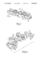
- FIG. 1 is a perspective view of a segment of a chain in accordance the present invention
- FIG. 2 is an exploded perspective view of a link of a chain in accordance with the present invention.
- FIG. 3 is a cross-sectional view taken along line 3--3 in FIG. 1;
- FIG. 4 is a cross-sectional view similar to FIG. 3, showing another embodiment of a chain in accordance with the present invention
- FIG. 5 shows a diagrammatic representation of a segment of a chain and rear sprockets while shifting up according to the present invention
- FIG. 6 shows a diagrammatic representation of a segment of a chain and front sprockets while shifting up according to the present invention
- FIG. 7 is top view of front chain rings operatively connected with a rear free wheels by a chain
- FIG. 8 shows a diagrammatic representation of a segment of a chain and rear sprockets while shifting up according to prior art
- FIG. 9 shows a diagrammatic representation of a segment of a chain and front sprockets while shifting up according to prior art.
- FIG. 10 is a cross-sectional view similar to FIG. 3, illustrating a chain according to prior art.
- FIG. 11 is a cross-sectional view similar to FIG. 3, illustrating a chain according to the inventor's co-pending U.S. patent application Ser. No. 07/637,293, U.S. Pat. No. 5,066,265.
- the chain is composed of a plurality of links.
- a link of the chain includes a first outer chain plate 1, a second outer chain plate 2, a first inner chain plate 3, a second inner chain plate 4, a pair of rollers 5a and 5b, and a pair of pins 6a and 6b.
- the dumbbell-shaped first outer chain plate 1 includes one straight waist portion disposed between two semi-circular end portions, an inner side 11 facing a sprocket when engaged formed with an incline 12 extending along an edge thereof, and holes 13a and 13b respectively formed in centers of the semi-circular end portions.
- the dumbbell-shaped second outer chain plate 2 includes one straight waist portion disposed between two semi-circular end portions, an inner face 21 formed with an incline 22 extending along an edge thereof, and holes 23a and 23b respectively formed in centers of the semi-circular end portions.
- the dumbbell-shaped first inner chain plate 3 includes one straight waist portion disposed between two semi-circular end portions, an inner face 31 formed with an incline 32 extending along an edge thereof, holes 33a and 33b respectively formed in centers of the semicircular end portions, and inward protuberant flanges 34a and 34b, respectively corresponding to the holes 33a and 33b, projecting from the inner face 31.
- the dumbbell-shaped second inner chain plate 4 includes one straight waist portion disposed between two semicircular end portions, an inner face 41 formed with an incline 42 extending along an edge thereof, holes 43a and 43b respectively formed in centers of the semi-circular end portions, and inward protuberant flanges 44a and 44b, respectively corresponding to the holes 43a and 43b, projecting from the inner face 41.
- the inner chain plates 3 and 4 are assembled with the flanges 34a and 44a aligning with each other and bearing the roller 5a, and with the flanges 34b and 44b aligning with each other and bearing the roller 5b.
- the pin 6b is inserted through the holes 23b and 43b, flanges 44b and 34b, and holes 33b and 13b, so that one link of the chain is assembled.
- the pin 6a is employed to engage one link with another.
- the first outer chain plate 1 has a transverse dimension greater than that of the second outer chain plate 2, while the first inner chain plate 3 has a transverse dimension greater than that of the second inner chain plate 4.
- the second outer chain plate includes a transverse dimension equal to that of the second inner chain plate.
- An incline only extends along an upper rim and a lower rim of the straight waist portion of the second outer chain plate.
- An incline only extends along an upper rim and a lower rim of the straight waist portion of the second inner chain plate.
- the chain is moved by a rear derailleur (not shown) away from the bicycle 70, e.g., from the front sprocket 91 to the front sprocket 92.
- the second outer chain plate 2 and the second chain plate 4 are employed.
- a tooth 910 smoothly slides relative to the link on the incline 22 or 42 and inserts into the space between the outer chain plates 1 and 3 or the space between the inner chain plates 2 and 4.
- the chain is moved by a front derailleur (not shown) away from the bicycle 70, e.g., from the front sprocket 81 to the front sprocket 82.
- the first outer chain plate 1 and the first inner chain plate 3 are employed to overcome the above-identified problem caused by the larger radial difference "b".
- a tooth 810 smoothly slides relative to the link on the incline 12 or 32 and inserts into the space between the outer chain plates 1 and 3 or the space between the inner chain plates 2 and 4.
Landscapes
- Engineering & Computer Science (AREA)
- General Engineering & Computer Science (AREA)
- Mechanical Engineering (AREA)
- Gears, Cams (AREA)
Abstract
A chain is a combination of plural links. Each link comprises a first inner chain plate, a second inner chain plate, a first outer chain plate, and a second outer chain plate linked by rollers and pins. Each chain plate includes a straight waist portion disposed between two semi-circular end portions, an inner face formed with an incline extending along an edge thereof, and a blade portion merging with the incline at the straight waist portion. The first outer chain plate includes a transverse dimension greater than that of the second outer chain plate, while the first inner chain plate includes a transverse dimension greater than that of the second inner chain plate.
Description
This invention relates to an improved chain, especially to a chain used on a bicycle.
Typically, a multi-sprocketed bicycle has front chain rings operatively connected with a rear free wheels by a chain, being controlled by a derailleur. Referring to FIG. 7, a modern bicycle is equipped with front chain rings 8 with up to three sprockets and a rear free wheels 9 with up to seven sprockets to possibly obtain twenty-one different gear ratios to suit different road conditions. The front chain rings 8 includes front sprockets 81, 82, and 83, arranged in a diametrical sequence with the smallest diametered front sprocket 81 closest to the bicycle 7. The rear free wheels 9 includes rear sprockets 91, 92, 93, 94, 95, 96, and 97, arranged in a diametrical sequence with the largest diametered rear sprocket 97 closest to the bicycle 7. The front sprocket 83 is connected with the rear sprocket 97 by a chain (shown in a phantom line). A radius difference "a" between two adjacent front sprockets is greater than a radius difference "b" between two adjacent rear sprockets. As a result, when a rider shifts, teeth of the rear sprockets can smoothly insert into the chain, but teeth of the front sprockets cannot quickly insert into the chain.
When a rider shifts up, referring to FIG. 8, a chain with a space "A" defined by two inner chain plates or a space "B" defined by two outer chain plates is received by a tooth 920 of a larger diametered sprocket, e.g., the sprocket 92; or shifts down, referring to FIG. 9, the chain is received on a smaller diametered sprocket, e.g., the sprocket 91, suiting different road conditions, such as flat or hilly. A conventional derailleur cooperating with a traditional chain does not allow the rider to shift quickly.
Referring to FIG. 10, it is found that while the rider is shifting, a top surface of a tooth of a sprocket abuts a lateral face of the chain plate according to prior art. As a result, the sprocket can not insert immediately into the space of the chain, thus delaying the rider since he has to continuously pedal to make the sprocket engage with the chain.
In the inventor's co-pending U.S. patent application Ser. No. 07/637,293, U.S. Pat. No. 5,066,265, referring to FIG. 11, a chain link includes two outer chain plates with inwardly inclines on tops and bottoms thereof and two inner chain plates with inwardly inclines on tops and bottoms thereof, so that the sprocket can insert easily and smoothly into the space of the chain.
Although the chain in accordance with the inventor's co-pending application can quickly engage with an intended rear sprocket when shifting, it can not quickly engage with an intended front sprocket when shifting up, as the radius difference "a" between two adjacent front sprockets is larger than the radius difference "b" between two adjacent rear sprockets.
The present invention provides an improved chain which is a combination of a plurality of links; each link has a pair of rollers, a pair of inner chain plates, and a pair of outer chain plates. The chain plates are dumbbell-shaped with a straight waist portion disposed between two semi-circular end portions.
The pair of inner chain plates includes a first inner chain plate which is distal from the bicycle when mounted and a second inner chain plate. The first inner chain plate is wider than the second inner chain plate and provides inward inclines along a top and a bottom thereof.
The pair of outer chains includes a first outer chain plate which is distal from the bicycle when mounted and a second outer chain plate. The first outer chain plate is wider than the second outer chain plate and provides inward inclines along a top and a bottom thereof.
Thus, after combining all of the elements above-mentioned, a link of the chain will provide a curved surface, with an inlet width between two inner chain plates larger than that of a traditional chain.
Therefore, it is an object of this invention to provide a link chain that facilitates a quick engagement of a chain with a front sprocket while shifting up.
FIG. 1 is a perspective view of a segment of a chain in accordance the present invention;
FIG. 2 is an exploded perspective view of a link of a chain in accordance with the present invention;
FIG. 3 is a cross-sectional view taken along line 3--3 in FIG. 1;
FIG. 4 is a cross-sectional view similar to FIG. 3, showing another embodiment of a chain in accordance with the present invention;
FIG. 5 shows a diagrammatic representation of a segment of a chain and rear sprockets while shifting up according to the present invention;
FIG. 6 shows a diagrammatic representation of a segment of a chain and front sprockets while shifting up according to the present invention;
FIG. 7 is top view of front chain rings operatively connected with a rear free wheels by a chain;
FIG. 8 shows a diagrammatic representation of a segment of a chain and rear sprockets while shifting up according to prior art;
FIG. 9 shows a diagrammatic representation of a segment of a chain and front sprockets while shifting up according to prior art.
FIG. 10 is a cross-sectional view similar to FIG. 3, illustrating a chain according to prior art; and
FIG. 11 is a cross-sectional view similar to FIG. 3, illustrating a chain according to the inventor's co-pending U.S. patent application Ser. No. 07/637,293, U.S. Pat. No. 5,066,265.
Referring to FIG. 1, a segment of a chain in accordance with the present invention is seen. The chain is composed of a plurality of links.
Referring to FIG. 2, a link of the chain includes a first outer chain plate 1, a second outer chain plate 2, a first inner chain plate 3, a second inner chain plate 4, a pair of rollers 5a and 5b, and a pair of pins 6a and 6b.
The dumbbell-shaped first outer chain plate 1 includes one straight waist portion disposed between two semi-circular end portions, an inner side 11 facing a sprocket when engaged formed with an incline 12 extending along an edge thereof, and holes 13a and 13b respectively formed in centers of the semi-circular end portions.
The dumbbell-shaped second outer chain plate 2 includes one straight waist portion disposed between two semi-circular end portions, an inner face 21 formed with an incline 22 extending along an edge thereof, and holes 23a and 23b respectively formed in centers of the semi-circular end portions.
The dumbbell-shaped first inner chain plate 3 includes one straight waist portion disposed between two semi-circular end portions, an inner face 31 formed with an incline 32 extending along an edge thereof, holes 33a and 33b respectively formed in centers of the semicircular end portions, and inward protuberant flanges 34a and 34b, respectively corresponding to the holes 33a and 33b, projecting from the inner face 31.
The dumbbell-shaped second inner chain plate 4 includes one straight waist portion disposed between two semicircular end portions, an inner face 41 formed with an incline 42 extending along an edge thereof, holes 43a and 43b respectively formed in centers of the semi-circular end portions, and inward protuberant flanges 44a and 44b, respectively corresponding to the holes 43a and 43b, projecting from the inner face 41.
The inner chain plates 3 and 4 are assembled with the flanges 34a and 44a aligning with each other and bearing the roller 5a, and with the flanges 34b and 44b aligning with each other and bearing the roller 5b.
The pin 6b is inserted through the holes 23b and 43b, flanges 44b and 34b, and holes 33b and 13b, so that one link of the chain is assembled. The pin 6a is employed to engage one link with another.
Referring to FIG. 3, the first outer chain plate 1 has a transverse dimension greater than that of the second outer chain plate 2, while the first inner chain plate 3 has a transverse dimension greater than that of the second inner chain plate 4.
Referring to FIG. 4, there is shown a cross-sectional view of another embodiment of a chain in accordance with the present application. The second outer chain plate includes a transverse dimension equal to that of the second inner chain plate. An incline only extends along an upper rim and a lower rim of the straight waist portion of the second outer chain plate. An incline only extends along an upper rim and a lower rim of the straight waist portion of the second inner chain plate.
Referring to FIG. 5, when the rider shifts up on the rear free wheels 9, the chain is moved by a rear derailleur (not shown) away from the bicycle 70, e.g., from the front sprocket 91 to the front sprocket 92. The second outer chain plate 2 and the second chain plate 4 are employed. A tooth 910 smoothly slides relative to the link on the incline 22 or 42 and inserts into the space between the outer chain plates 1 and 3 or the space between the inner chain plates 2 and 4.
Referring to FIG. 6, when the rider shifts up on the front chain rings 8, the chain is moved by a front derailleur (not shown) away from the bicycle 70, e.g., from the front sprocket 81 to the front sprocket 82. The first outer chain plate 1 and the first inner chain plate 3 are employed to overcome the above-identified problem caused by the larger radial difference "b". A tooth 810 smoothly slides relative to the link on the incline 12 or 32 and inserts into the space between the outer chain plates 1 and 3 or the space between the inner chain plates 2 and 4.
Even though numerous characteristics and advantages of the present invention have been set forth in the foregoing description, the disclosure is illustrative only. Variations ma be made within the principles of the invention to the full extend as indicated by the broad general meaning of the claims.
Claims (11)
1. A chain comprising plural links each consisting of a first inner chain plate, a second inner chain plate, a first outer chain plate, and a second outer chain plate linked by rollers and pins, wherein the improvement comprises:
each chain plate including one straight waist portion disposed between two semi-circular end portions and an inner side facing a sprocket when engaged;
said first outer chain plate including a transverse dimension greater than that of said second outer chain plate and that of said first inner chain plate, while said first inner chain plate including a transverse dimension no less than that of said second inner chain plate; and
said inner sides of said first outer chain plate and said first inner chain plate each including an edge defining an incline extending along said edge of said inner side;
2. A chain as claimed in claim 1, wherein said incline of said first inner chain plate is positioned successively to said incline of said first outer chain plate as to form a smooth curved surface thereon at a junction thereof.
3. A chain in accordance with claim 1, wherein said second outer chain plate includes a transverse dimension no less than that of said second inner chain plate.
4. A chain in accordance with claim 3, wherein said second outer chain plate includes a transverse dimension equal to that of said second inner chain plate; and
said inner sides of said second outer chain plate and said second inner chain plate each including an incline extending alone a top and a bottom of said straight waist.
5. A chain in accordance with claim 3, wherein said second outer chain plate includes a transverse dimension greater than that of said second inner chain plate; and
said inner sides of said second outer chain plate and said second inner chain plate each including an edge defining an incline extending along said edge of said inner side.
6. A chain as claimed in claim 5, wherein said incline of said second inner chain plate is positioned successively to said incline of said second outer chain plate as to form a smooth curved surface thereon at a junction thereof.
7. A chain comprising plural links each consisting of a first inner chain plate, a second inner chain plate, a first outer chain plate, and a second outer chain plate linked by rollers and pins, wherein the improvement comprises:
each chain plate including one straight waist portion disposed between two semi-circular end portions and an inner side facing a sprocket when being engaged;
said first outer chain plate including a transverse dimension greater than that of said second outer chain plate and that of said first inner chain plate, while said first inner chain plate including a transverse dimension no less than that of said second inner chain plate;
said inner sides of said first outer chain plate and said first inner chain plate each including a rim defining an incline extending along said edge of said inner face; and
said incline of said first inner chain plate is positioned successively to said incline of said first outer chain plate as to form a smooth curved surface thereon at a junction thereof.
8. A chain in accordance with claim 7, wherein said second outer chain plate includes a transverse dimension no less than that of said second inner chain plate.
9. A chain in accordance with claim 8, wherein said second outer chain plate includes a transverse dimension equal to that of said second inner chain plate; and
said inner sides of said second outer chain plate and said second inner chain plate each including an incline extending alone an upper rim and a lower rim of said straight waists.
10. A chain in accordance with claim 8, wherein said second outer chain plate includes a transverse dimension greater than that of said second inner chain plate; and
said inner sides of said second outer chain plate and said second inner chain plate each including a rim defining an incline extending therearound.
11. A chain as claimed in claim 10, wherein said incline of said second inner chain plate is positioned successively to said incline of said second outer chain plate as to form a smooth curved surface thereon at a junction thereof.
Priority Applications (1)
| Application Number | Priority Date | Filing Date | Title |
|---|---|---|---|
| US07/721,877 US5098349A (en) | 1991-06-27 | 1991-06-27 | Chain |
Applications Claiming Priority (1)
| Application Number | Priority Date | Filing Date | Title |
|---|---|---|---|
| US07/721,877 US5098349A (en) | 1991-06-27 | 1991-06-27 | Chain |
Publications (1)
| Publication Number | Publication Date |
|---|---|
| US5098349A true US5098349A (en) | 1992-03-24 |
Family
ID=24899681
Family Applications (1)
| Application Number | Title | Priority Date | Filing Date |
|---|---|---|---|
| US07/721,877 Expired - Fee Related US5098349A (en) | 1991-06-27 | 1991-06-27 | Chain |
Country Status (1)
| Country | Link |
|---|---|
| US (1) | US5098349A (en) |
Cited By (28)
| Publication number | Priority date | Publication date | Assignee | Title |
|---|---|---|---|---|
| US5465568A (en) * | 1995-01-17 | 1995-11-14 | Yaban Chain Industrial Co., Ltd. | Chain structure for bicycles |
| US5799479A (en) * | 1996-02-13 | 1998-09-01 | Tsubakimoto Chain Co. | Wear-resisting low noise chain |
| US5803853A (en) * | 1997-06-30 | 1998-09-08 | Kmc Chain Industrial Co., Ltd. | Bicycle drive chain |
| US6364799B1 (en) * | 1999-04-13 | 2002-04-02 | Campagnolo Srl | Quick-connection link, for a bicycle chain |
| US6450910B1 (en) | 1999-06-02 | 2002-09-17 | Tsubakimoto Chain Co. | Link plate for silent chains and method of producing the same |
| US20040091333A1 (en) * | 2002-08-16 | 2004-05-13 | Textron Inc. | Split weld cage nut assembly |
| US20050155194A1 (en) * | 2002-04-23 | 2005-07-21 | Tor Christiansson | Device for fastening emergency equipment to a ship's deck |
| US20050202914A1 (en) * | 2004-03-10 | 2005-09-15 | Sram Deutschland Gmbh | Bicycle chain |
| US20080119312A1 (en) * | 2006-11-16 | 2008-05-22 | Shimano Inc. | Bicycle outer chain link |
| US20100050590A1 (en) * | 2008-08-26 | 2010-03-04 | Taila Shnayder | Marine safety device attachment with automatic release capability |
| US20110251005A1 (en) * | 2010-04-13 | 2011-10-13 | Detlef Ragnitz | Roller chain |
| US20120322599A1 (en) * | 2011-06-15 | 2012-12-20 | Shimano Inc. | Inner link plate for bicycle chain |
| US20130150195A1 (en) * | 2011-12-12 | 2013-06-13 | Renold Plc. | Chain |
| US20130203538A1 (en) * | 2012-02-03 | 2013-08-08 | Tsubakimoto Chain Co. | Chain |
| DE19547846B4 (en) * | 1994-12-21 | 2015-01-29 | Borgwarner Inc. | Roller chain pins with minimal projection |
| US20150094182A1 (en) * | 2013-09-27 | 2015-04-02 | Shimano (Singapore) Pte. Ltd. | Bicycle chain |
| US20150148164A1 (en) * | 2013-11-28 | 2015-05-28 | Tsubakimoto Chain Co. | Metal chain |
| US9303725B2 (en) | 2013-09-27 | 2016-04-05 | Shimano Inc. | Bicycle chain |
| US20170067536A1 (en) * | 2015-09-09 | 2017-03-09 | Sram, Llc | Roller chain inner plate |
| US20180017131A1 (en) * | 2016-07-15 | 2018-01-18 | Shimano Inc. | Link plates for bicycle chain |
| US20180201341A1 (en) * | 2017-01-13 | 2018-07-19 | Kmc Chain Industrial Co., Ltd. | Chain |
| US20190101189A1 (en) * | 2017-09-29 | 2019-04-04 | Shimano Inc. | Bicycle-chain outer link plate and bicycle chain |
| US10352397B2 (en) * | 2017-03-01 | 2019-07-16 | Shimano Inc. | Bicycle chain |
| US10371234B2 (en) * | 2015-11-06 | 2019-08-06 | Campagnolo S.R.L. | Bicycle chain and motion transmission system comprising such a chain |
| US10760647B2 (en) * | 2018-06-01 | 2020-09-01 | TH Industries Co., LTD | Drive chain for bicycle |
| US10774904B1 (en) * | 2019-12-18 | 2020-09-15 | Hasanen Mohammed Hussen | Torsional spring tensioning system for a power transmission chain |
| US11174915B2 (en) * | 2018-05-11 | 2021-11-16 | Sram Deutschland Gmbh | Asymmetric bicycle chain link |
| US11767078B2 (en) * | 2019-02-05 | 2023-09-26 | Sram Deutschland Gmbh | Drive arrangement for a bicycle |
Citations (8)
| Publication number | Priority date | Publication date | Assignee | Title |
|---|---|---|---|---|
| US623431A (en) * | 1899-04-18 | Drive-chain and chain-wheel | ||
| US1945357A (en) * | 1931-05-16 | 1934-01-30 | Link Belt Co | Chain |
| US2568649A (en) * | 1947-12-24 | 1951-09-18 | Smith Mitchell | Chain structure |
| US3359815A (en) * | 1963-09-26 | 1967-12-26 | Morse Chain Co | Power transmission chain link plate |
| US4102216A (en) * | 1975-12-29 | 1978-07-25 | Shimano Industrial Company Limited | Driving chain for bicycles |
| US4265134A (en) * | 1977-07-06 | 1981-05-05 | Compagnie Des Transmissions Mecaniques Sedis | Transmission chain |
| US4596539A (en) * | 1985-05-07 | 1986-06-24 | Maeda Industries, Ltd. | Bicycle drive chain |
| US4642078A (en) * | 1984-08-03 | 1987-02-10 | Compagnie Des Transmissions Mecaniques Sedis | Transmission chain |
-
1991
- 1991-06-27 US US07/721,877 patent/US5098349A/en not_active Expired - Fee Related
Patent Citations (8)
| Publication number | Priority date | Publication date | Assignee | Title |
|---|---|---|---|---|
| US623431A (en) * | 1899-04-18 | Drive-chain and chain-wheel | ||
| US1945357A (en) * | 1931-05-16 | 1934-01-30 | Link Belt Co | Chain |
| US2568649A (en) * | 1947-12-24 | 1951-09-18 | Smith Mitchell | Chain structure |
| US3359815A (en) * | 1963-09-26 | 1967-12-26 | Morse Chain Co | Power transmission chain link plate |
| US4102216A (en) * | 1975-12-29 | 1978-07-25 | Shimano Industrial Company Limited | Driving chain for bicycles |
| US4265134A (en) * | 1977-07-06 | 1981-05-05 | Compagnie Des Transmissions Mecaniques Sedis | Transmission chain |
| US4642078A (en) * | 1984-08-03 | 1987-02-10 | Compagnie Des Transmissions Mecaniques Sedis | Transmission chain |
| US4596539A (en) * | 1985-05-07 | 1986-06-24 | Maeda Industries, Ltd. | Bicycle drive chain |
Cited By (44)
| Publication number | Priority date | Publication date | Assignee | Title |
|---|---|---|---|---|
| DE19547846B4 (en) * | 1994-12-21 | 2015-01-29 | Borgwarner Inc. | Roller chain pins with minimal projection |
| US5465568A (en) * | 1995-01-17 | 1995-11-14 | Yaban Chain Industrial Co., Ltd. | Chain structure for bicycles |
| US5799479A (en) * | 1996-02-13 | 1998-09-01 | Tsubakimoto Chain Co. | Wear-resisting low noise chain |
| US5803853A (en) * | 1997-06-30 | 1998-09-08 | Kmc Chain Industrial Co., Ltd. | Bicycle drive chain |
| US6364799B1 (en) * | 1999-04-13 | 2002-04-02 | Campagnolo Srl | Quick-connection link, for a bicycle chain |
| US6450910B1 (en) | 1999-06-02 | 2002-09-17 | Tsubakimoto Chain Co. | Link plate for silent chains and method of producing the same |
| US20050155194A1 (en) * | 2002-04-23 | 2005-07-21 | Tor Christiansson | Device for fastening emergency equipment to a ship's deck |
| US7302739B2 (en) * | 2002-04-23 | 2007-12-04 | C M Hammar Utveckling Ab | Device for fastening emergency equipment to a ship's deck |
| US20040091333A1 (en) * | 2002-08-16 | 2004-05-13 | Textron Inc. | Split weld cage nut assembly |
| US20050202914A1 (en) * | 2004-03-10 | 2005-09-15 | Sram Deutschland Gmbh | Bicycle chain |
| US7946941B2 (en) * | 2006-11-16 | 2011-05-24 | Shimano Inc. | Bicycle outer chain link |
| US20080119312A1 (en) * | 2006-11-16 | 2008-05-22 | Shimano Inc. | Bicycle outer chain link |
| US20100050590A1 (en) * | 2008-08-26 | 2010-03-04 | Taila Shnayder | Marine safety device attachment with automatic release capability |
| US20100257836A1 (en) * | 2008-08-26 | 2010-10-14 | Taila Shnayder | Marine safety device attachment with automatic release capability |
| US7971422B2 (en) | 2008-08-26 | 2011-07-05 | General Pneumatics Corp. | Marine safety device attachment with automatic release capability |
| US7743597B2 (en) | 2008-08-26 | 2010-06-29 | General Pneumatics Corp. | Marine safety device attachment with automatic release capability |
| US20110251005A1 (en) * | 2010-04-13 | 2011-10-13 | Detlef Ragnitz | Roller chain |
| US20120322599A1 (en) * | 2011-06-15 | 2012-12-20 | Shimano Inc. | Inner link plate for bicycle chain |
| US8734280B2 (en) * | 2011-06-15 | 2014-05-27 | Shimano Inc. | Inner link plate for bicycle chain |
| US20130150195A1 (en) * | 2011-12-12 | 2013-06-13 | Renold Plc. | Chain |
| US20130203538A1 (en) * | 2012-02-03 | 2013-08-08 | Tsubakimoto Chain Co. | Chain |
| US8968132B2 (en) * | 2012-02-03 | 2015-03-03 | Tsubakimoto Chain Co. | Chain |
| US20150094182A1 (en) * | 2013-09-27 | 2015-04-02 | Shimano (Singapore) Pte. Ltd. | Bicycle chain |
| US9255624B2 (en) * | 2013-09-27 | 2016-02-09 | Shimano Inc. | Bicycle chain |
| US9303725B2 (en) | 2013-09-27 | 2016-04-05 | Shimano Inc. | Bicycle chain |
| US9494214B2 (en) * | 2013-11-28 | 2016-11-15 | Tsubakimoto Chain Co. | Metal chain |
| US20150148164A1 (en) * | 2013-11-28 | 2015-05-28 | Tsubakimoto Chain Co. | Metal chain |
| US20170067536A1 (en) * | 2015-09-09 | 2017-03-09 | Sram, Llc | Roller chain inner plate |
| US11384815B2 (en) * | 2015-09-09 | 2022-07-12 | Sram Deutschland Gmbh | Roller chain inner plate |
| US10533633B2 (en) * | 2015-09-09 | 2020-01-14 | Sram Deutschland, Gmbh | Roller chain inner plate |
| US10371234B2 (en) * | 2015-11-06 | 2019-08-06 | Campagnolo S.R.L. | Bicycle chain and motion transmission system comprising such a chain |
| US20180017131A1 (en) * | 2016-07-15 | 2018-01-18 | Shimano Inc. | Link plates for bicycle chain |
| US10641356B2 (en) * | 2016-07-15 | 2020-05-05 | Shimano Inc. | Link plates for bicycle chain |
| US9939045B2 (en) * | 2016-07-15 | 2018-04-10 | Shimano Inc. | Link plates for bicycle chain |
| US20180201341A1 (en) * | 2017-01-13 | 2018-07-19 | Kmc Chain Industrial Co., Ltd. | Chain |
| US10352397B2 (en) * | 2017-03-01 | 2019-07-16 | Shimano Inc. | Bicycle chain |
| US20190101189A1 (en) * | 2017-09-29 | 2019-04-04 | Shimano Inc. | Bicycle-chain outer link plate and bicycle chain |
| US10982733B2 (en) * | 2017-09-29 | 2021-04-20 | Shimano Inc. | Bicycle-chain outer link plate and bicycle chain |
| US11174915B2 (en) * | 2018-05-11 | 2021-11-16 | Sram Deutschland Gmbh | Asymmetric bicycle chain link |
| US20220056984A1 (en) * | 2018-05-11 | 2022-02-24 | Sram Deutschland Gmbh | Asymmetric bicycle chain link |
| US11867256B2 (en) * | 2018-05-11 | 2024-01-09 | Sram Deutschland Gmbh | Asymmetric bicycle chain link |
| US10760647B2 (en) * | 2018-06-01 | 2020-09-01 | TH Industries Co., LTD | Drive chain for bicycle |
| US11767078B2 (en) * | 2019-02-05 | 2023-09-26 | Sram Deutschland Gmbh | Drive arrangement for a bicycle |
| US10774904B1 (en) * | 2019-12-18 | 2020-09-15 | Hasanen Mohammed Hussen | Torsional spring tensioning system for a power transmission chain |
Similar Documents
| Publication | Publication Date | Title |
|---|---|---|
| US5098349A (en) | Chain | |
| US5066265A (en) | Chain | |
| US5545096A (en) | Sprocket mechanism for a multistage bicycle | |
| US9376165B2 (en) | Bicycle sprocket | |
| US4889521A (en) | Multistage sprocket assembly for a bicycle | |
| US5514042A (en) | Multistage sprocket mechanism for a bicycle | |
| US6572500B2 (en) | Bicycle sprocket with chain support projections | |
| US9731791B2 (en) | Chainring | |
| US5741196A (en) | Transmission chain particularly for a bicycle | |
| US6039665A (en) | Multiple sprocket assembly for a bicycle | |
| US4493678A (en) | Expandible sprocket | |
| US5073151A (en) | Multi-speed sprocket assembly for bicycle | |
| US5192249A (en) | Multi-stage sprocket assembly for bicycle | |
| EP0479032B1 (en) | Multiple sprocket assembly for bicycle | |
| US4102216A (en) | Driving chain for bicycles | |
| GB2277138A (en) | Bicycle chain | |
| US5226857A (en) | Chain for a bicycle | |
| US5921881A (en) | Narrow bicycle chain with inner links that receive sprocket teeth within a bottom recess | |
| US5569107A (en) | Multi-step bicycle transmission sprocket assembly | |
| US5437577A (en) | Chain for a bicycle with derailleur | |
| US5591095A (en) | Chain for a bicycle with derailleur | |
| JP2500574Y2 (en) | Chain | |
| CA2033749A1 (en) | Chain | |
| TWI891270B (en) | Bicycle sprocket structure | |
| JPH072655U (en) | Improved chain |
Legal Events
| Date | Code | Title | Description |
|---|---|---|---|
| FPAY | Fee payment |
Year of fee payment: 4 |
|
| REMI | Maintenance fee reminder mailed | ||
| LAPS | Lapse for failure to pay maintenance fees | ||
| FP | Lapsed due to failure to pay maintenance fee |
Effective date: 20000324 |
|
| STCH | Information on status: patent discontinuation |
Free format text: PATENT EXPIRED DUE TO NONPAYMENT OF MAINTENANCE FEES UNDER 37 CFR 1.362 |