US5097866A - Refrigerant metering device - Google Patents
Refrigerant metering device Download PDFInfo
- Publication number
- US5097866A US5097866A US07/559,769 US55976990A US5097866A US 5097866 A US5097866 A US 5097866A US 55976990 A US55976990 A US 55976990A US 5097866 A US5097866 A US 5097866A
- Authority
- US
- United States
- Prior art keywords
- restrictor
- filter
- section
- metering device
- casing
- Prior art date
- Legal status (The legal status is an assumption and is not a legal conclusion. Google has not performed a legal analysis and makes no representation as to the accuracy of the status listed.)
- Expired - Fee Related
Links
- 239000003507 refrigerant Substances 0.000 title claims abstract description 25
- 239000011148 porous material Substances 0.000 claims abstract description 11
- 238000011144 upstream manufacturing Methods 0.000 claims abstract description 8
- 238000005057 refrigeration Methods 0.000 abstract description 14
- 239000000463 material Substances 0.000 abstract description 11
- -1 polyethylene Polymers 0.000 abstract description 8
- 239000004698 Polyethylene Substances 0.000 abstract description 7
- 230000006835 compression Effects 0.000 abstract description 7
- 238000007906 compression Methods 0.000 abstract description 7
- 229920000573 polyethylene Polymers 0.000 abstract description 7
- 230000009467 reduction Effects 0.000 abstract description 7
- 230000015556 catabolic process Effects 0.000 abstract description 2
- 238000006731 degradation reaction Methods 0.000 abstract description 2
- 238000009434 installation Methods 0.000 abstract description 2
- 238000005219 brazing Methods 0.000 description 3
- 239000007788 liquid Substances 0.000 description 3
- 230000007704 transition Effects 0.000 description 3
- RYGMFSIKBFXOCR-UHFFFAOYSA-N Copper Chemical compound [Cu] RYGMFSIKBFXOCR-UHFFFAOYSA-N 0.000 description 2
- 230000008859 change Effects 0.000 description 2
- 229910052802 copper Inorganic materials 0.000 description 2
- 239000010949 copper Substances 0.000 description 2
- 230000007423 decrease Effects 0.000 description 2
- 238000010586 diagram Methods 0.000 description 2
- 238000001914 filtration Methods 0.000 description 2
- 238000000034 method Methods 0.000 description 2
- 230000008569 process Effects 0.000 description 2
- 125000006850 spacer group Chemical group 0.000 description 2
- 241001572351 Lycaena dorcas Species 0.000 description 1
- 239000004809 Teflon Substances 0.000 description 1
- 229920006362 Teflon® Polymers 0.000 description 1
- 238000004378 air conditioning Methods 0.000 description 1
- 230000008878 coupling Effects 0.000 description 1
- 238000010168 coupling process Methods 0.000 description 1
- 238000005859 coupling reaction Methods 0.000 description 1
- 239000010687 lubricating oil Substances 0.000 description 1
- 238000004519 manufacturing process Methods 0.000 description 1
- 238000002844 melting Methods 0.000 description 1
- 230000008018 melting Effects 0.000 description 1
- 238000012986 modification Methods 0.000 description 1
- 230000004048 modification Effects 0.000 description 1
- 229920001343 polytetrafluoroethylene Polymers 0.000 description 1
- 239000004810 polytetrafluoroethylene Substances 0.000 description 1
- 238000000926 separation method Methods 0.000 description 1
- 238000004513 sizing Methods 0.000 description 1
Images
Classifications
-
- F—MECHANICAL ENGINEERING; LIGHTING; HEATING; WEAPONS; BLASTING
- F25—REFRIGERATION OR COOLING; COMBINED HEATING AND REFRIGERATION SYSTEMS; HEAT PUMP SYSTEMS; MANUFACTURE OR STORAGE OF ICE; LIQUEFACTION SOLIDIFICATION OF GASES
- F25B—REFRIGERATION MACHINES, PLANTS OR SYSTEMS; COMBINED HEATING AND REFRIGERATION SYSTEMS; HEAT PUMP SYSTEMS
- F25B43/00—Arrangements for separating or purifying gases or liquids; Arrangements for vaporising the residuum of liquid refrigerant, e.g. by heat
- F25B43/003—Filters
-
- F—MECHANICAL ENGINEERING; LIGHTING; HEATING; WEAPONS; BLASTING
- F25—REFRIGERATION OR COOLING; COMBINED HEATING AND REFRIGERATION SYSTEMS; HEAT PUMP SYSTEMS; MANUFACTURE OR STORAGE OF ICE; LIQUEFACTION SOLIDIFICATION OF GASES
- F25B—REFRIGERATION MACHINES, PLANTS OR SYSTEMS; COMBINED HEATING AND REFRIGERATION SYSTEMS; HEAT PUMP SYSTEMS
- F25B41/00—Fluid-circulation arrangements
- F25B41/30—Expansion means; Dispositions thereof
-
- Y—GENERAL TAGGING OF NEW TECHNOLOGICAL DEVELOPMENTS; GENERAL TAGGING OF CROSS-SECTIONAL TECHNOLOGIES SPANNING OVER SEVERAL SECTIONS OF THE IPC; TECHNICAL SUBJECTS COVERED BY FORMER USPC CROSS-REFERENCE ART COLLECTIONS [XRACs] AND DIGESTS
- Y10—TECHNICAL SUBJECTS COVERED BY FORMER USPC
- Y10T—TECHNICAL SUBJECTS COVERED BY FORMER US CLASSIFICATION
- Y10T137/00—Fluid handling
- Y10T137/794—With means for separating solid material from the fluid
- Y10T137/8122—Planar strainer normal to flow path
Definitions
- This invention relates generally to devices for metering the flow of refrigerant in a vapor compression refrigeration system. More particularly, the invention relates to a metering device that is effective in reducing refrigerant flow noise during both steady state operation and after shutdown of the refrigeration system in which the device is installed.
- One of the essential components of a closed cycle vapor compression refrigeration system is a metering or expansion means for effecting a drop in the refrigerant pressure at one point in the cycle, thus causing a change of refrigerant state from liquid to gas and a reduction in refrigerant pressure and temperature due to adiabatic expansion.
- Many types of such metering devices are known in the art, including thermoexpansion valves, Accurator®, orifices and capillary tubes.
- Capillary tubes because of their relatively small size and low cost, are commonly found in small to medium capacity refrigeration systems such as room air conditioners and packaged terminal air conditioners.
- An objective in the design and manufacture of a refrigeration system is to reduce the sound radiated by the system, not only during operation but also during post shutdown transients.
- One source of sound in a refrigeration system is the metering device.
- High velocity liquid refrigerant passing through a capillary tube metering device during system operation can be a source of objectionable noise.
- the passage of high velocity gaseous refrigerant through a capillary tube metering device during system shutdown can also radiate noise of a different but still objectionable nature.
- the objects of the present invention are to provide a low cost refrigerant metering device for a vapor compression refrigeration system that offers performance comparable to a capillary tube but produces less noise during both system operation and shutdown transients.
- the present invention achieves these objects in a refrigerant metering device that employs a restrictor fabricated of a porous material to achieve the desired pressure reduction across the device.
- the porous material is housed in a casing that provides support for the restrictor and enables installation of the device into a refrigeration system. Any suitable porous material may be used to make the restrictor, but in the preferred embodiments, a porous polyethylene material is used.
- a filter is provided upstream in the refrigerant flow path from the restrictor to reduce the possibility of restrictor fouling and resultant system performance degradation.
- the device thus serves to provide metering, filtration and sound attenuation functions all in one.
- the filter and restrictor are combined as two sections of an integral filter and restrictor.
- the device of the present invention is capable for use as a metering device in any application in which a capillary tube would be commonly used but is particularly suitable for use in applications where noise reduction is a significant performance goal, such as in room air conditioners and packaged terminal air conditioning systems.
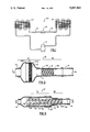
- FIG. 1 is a schematic diagram of a typical vapor compression refrigeration system in which the present invention is used.
- FIG. 2 is a cross sectioned elevation view of one embodiment of the present invention.
- FIG. 3 is a cross sectioned elevation view of another embodiment of the present invention.
- FIG. 1 is a schematic diagram of a typical closed cycle vapor compression refrigeration system 100.
- System 100 comprises compressor 101, condenser 102, metering device 110 and evaporator 103 interconnected in a closed circuit by piping or tubing.
- Feeder tubes 141 connect condenser 102 with metering device 110 and metering device 110 with evaporator 103.
- Refrigerant flows through system 100 from the discharge of compressor 101 to and through condenser 102, then through metering device 110, where it undergoes a pressure reduction, phase change from a liquid to a gas and a reduction in temperature due to adiabatic expansion. From metering device 110, the refrigerant then flows through evaporator 103 before returning to the suction of compressor 101.
- FIG. 2 shows metering device 10 installed between two sections of feeder tubing 41 in a refrigeration system.
- Arrow A shows the direction of refrigerant flow through device 10.
- Generally cylindrical device 10 comprises filter 21 and restrictor 31 housed in casing 11 and may be divided into two sections: filter section 20 and restrictor section 30.
- Filter section 20 comprises bells 22A and 22B and sleeve 23 containing filter 21.
- Restrictor section comprises restrictor housing 32 containing restrictor 31
- Restrictor 31 and restrictor housing 32 are sized for a close interference fit between the two members, both to prevent the bypassing of refrigerant around restrictor 31 and to retain restrictor 31 within restrictor housing 32.
- crimp 32 in restrictor housing 21 insures that restrictor 31 will not be ejected from device 1 into the system downstream under the force of the differential pressure across restrictor 31.
- Filter 21 and casing bell 22B are sized for a close interference fit for like reasons. Casing bell 22B also prevents downstream movement of filter 21.
- FIG. 3 shows metering device 50 installed between two sections of feeder tubing 41 in a refrigeration system.
- the arrows show the direction of flow of refrigerant through device 50.
- Generally cylindrical device 50 comprises integral filter and restrictor 61 housed in casing 51.
- Casing 51 comprises sleeve 52, into which is inserted spacer 55, coupling 53, bushing 54 and transition piece 56.
- Device 50 may be divided into filter section 70 and restrictor section 80. At its upstream or inlet end, integral filter and restrictor 61 has shoulder 63.
- integral filter and restrictor 61 Over the length of filter section 70, the outer diameter of integral filter and restrictor 61 is less than the inner diameter of casing 51 and gradually tapers or decreases from its upstream toward its downstream end. Annular chamber 71 is thus formed between the inner wall of casing 51 and the outer wall of integral filter and restrictor 61. Also over the length of filter section 70, integral filter and restrictor 61 has central cavity 62, whose diameter decreases from its upstream toward its downstream end so that a wall of constant thickness is formed between cavity 62 and the outer surface of the integral filter and restrictor.
- the diameter of the downstream end of integral filter and restrictor 61 and the diameters of bushing 54 and transition piece 56 within restrictor section 80 are sized for a close interference fit to prevent bypassing of refrigerant around integral filter and restrictor 61. Shoulder 63 bears against spacer 55 to prevent movement of integral filter and restrictor 61 within casing 51. Refrigerant entering metering device 50 flows from cavity 62 through the filter section of integral filter and restrictor 61 into and through annular chamber 71 and then through the restrictor section of integral filter and restrictor 61 before leaving the device.
- All parts of the casings of both metering device 10 (FIG. 2) and metering device 50 (FIG. 3) may be fabricated of any suitable material, such as copper, and joined together by a suitable process such as brazing.
- filter 21 and restrictor 31 may be fabricated of any suitable material.
- FIG. 2 shows filter 14 to be a mesh or screen, but it may be fabricated of the same material as restrictor 31.
- An excellent choice of materials for restrictor 31 is porous polyethylene, because it is compatible with commonly used refrigerants and lubricating oils and is relatively low in cost.
- a disadvantage of porous polyethylene is its low melting temperature as compared to the temperatures usually found in brazing processes. This limitation can be overcome by using heat sinks during assembly and by sizing the parts to provide adequate separation between the polyethylene members and the brazing sites.
- An alternative material having slightly better heat resistance is porous polytetrafluoroethylene (e.g. Teflon) but this material would also require assembly precautions.
- Porous copper has excellent heat resistance and performs acceptably as a restrictor but is several orders of magnitude more expensive than polyethylene.
- filter 21 (FIG. 2) and the filter section of integral filter and restrictor 61 (FIG. 3) be a minimum. If filter 21, for example, is made of the same material as restrictor 31, it should have a relatively large frontal surface and be relatively thin. Tested designs have shown that for a restrictor diameter of 0.25 inch (6 mm), the filter should have a diameter of 1 inch (25 mm) and a thickness of about 0.1 inch (2.5 mm).
- the magnitude of the pressure drop across a restrictor of a given diameter and made of a material having pores of a given size is a function of its length.
- Tests of a restrictor made of porous polyethylene having a pore size of 250 microns and having a diameter of 0.25 inch (6 mm) and a length of 0.5 inch (12.5 mm) produced pressure drops of about 47 psi (33 kPa).
- 0.25 inch (6 mm) is a convenient diameter for a restrictor because it fits well into the 5/16 inch (8 mm) O.D. copper tubing that is commonly used in room air conditioners.
- casings of the same overall size could be fitted with restrictors having different pore sizes and lengths to make metering devices having different pressure reducing characteristics and thus suitable for use in a variety of applications.
- the pressure reducing characteristics of the device may be varied by both varying the size of the pores in the material in the integral filter and restrictor and by controlling how far the restrictor portion is inserted into the transition tube.
- Tests of the present invention on a room air conditioner of moderate size have shown noise reductions of 6 dbA (from that of the same unit operating with a capillary tube as a metering device) in that portion of the total radiated noise level that is attributable to refrigerant flow through the metering device.
Landscapes
- Engineering & Computer Science (AREA)
- Physics & Mathematics (AREA)
- Mechanical Engineering (AREA)
- Thermal Sciences (AREA)
- General Engineering & Computer Science (AREA)
- Chemical & Material Sciences (AREA)
- Analytical Chemistry (AREA)
- Power Engineering (AREA)
- Measuring Fluid Pressure (AREA)
Abstract
A refrigerant metering device for a vapor compression refrigeration system. The metering device employs a restrictor fabricated of a porous material to achieve the desired pressure reduction across the device. The porous material is housed in a casing that provides support for the restrictor and enables installation of the device into the system. Any suitable porous material may be used to make the restrictor, but in the preferred embodiments, a porous polyethylene material is used. In the preferred embodiments, a filter is provided upstream in the refrigerant flow path to reduce the possibility of restrictor fouling and resultant system performance degradation. In one embodiment, the filter and restrictor are combined as two sections of an integral filter and restrictor. The device is effective in reducing refrigerant flow noise during both steady state operation and post shutdown transients.
Description
This invention relates generally to devices for metering the flow of refrigerant in a vapor compression refrigeration system. More particularly, the invention relates to a metering device that is effective in reducing refrigerant flow noise during both steady state operation and after shutdown of the refrigeration system in which the device is installed.
One of the essential components of a closed cycle vapor compression refrigeration system is a metering or expansion means for effecting a drop in the refrigerant pressure at one point in the cycle, thus causing a change of refrigerant state from liquid to gas and a reduction in refrigerant pressure and temperature due to adiabatic expansion. Many types of such metering devices are known in the art, including thermoexpansion valves, Accurator®, orifices and capillary tubes. Capillary tubes, because of their relatively small size and low cost, are commonly found in small to medium capacity refrigeration systems such as room air conditioners and packaged terminal air conditioners.
An objective in the design and manufacture of a refrigeration system, particularly one that is intended to operate in or near inhabited areas, is to reduce the sound radiated by the system, not only during operation but also during post shutdown transients. One source of sound in a refrigeration system is the metering device. High velocity liquid refrigerant passing through a capillary tube metering device during system operation can be a source of objectionable noise. The passage of high velocity gaseous refrigerant through a capillary tube metering device during system shutdown can also radiate noise of a different but still objectionable nature.
What is needed therefore, is a metering device that reduces the radiated noise level of a vapor compression refrigeration system.
The objects of the present invention are to provide a low cost refrigerant metering device for a vapor compression refrigeration system that offers performance comparable to a capillary tube but produces less noise during both system operation and shutdown transients.
The present invention achieves these objects in a refrigerant metering device that employs a restrictor fabricated of a porous material to achieve the desired pressure reduction across the device. The porous material is housed in a casing that provides support for the restrictor and enables installation of the device into a refrigeration system. Any suitable porous material may be used to make the restrictor, but in the preferred embodiments, a porous polyethylene material is used. In the preferred embodiments, a filter is provided upstream in the refrigerant flow path from the restrictor to reduce the possibility of restrictor fouling and resultant system performance degradation. The device thus serves to provide metering, filtration and sound attenuation functions all in one. In one preferred embodiment, the filter and restrictor are combined as two sections of an integral filter and restrictor.
The device of the present invention is capable for use as a metering device in any application in which a capillary tube would be commonly used but is particularly suitable for use in applications where noise reduction is a significant performance goal, such as in room air conditioners and packaged terminal air conditioning systems.
The accompanying drawings form a part of the specification. Throughout the drawings, like reference numbers identify like elements.
FIG. 1 is a schematic diagram of a typical vapor compression refrigeration system in which the present invention is used.
FIG. 2 is a cross sectioned elevation view of one embodiment of the present invention.
FIG. 3 is a cross sectioned elevation view of another embodiment of the present invention.
FIG. 1 is a schematic diagram of a typical closed cycle vapor compression refrigeration system 100. System 100 comprises compressor 101, condenser 102, metering device 110 and evaporator 103 interconnected in a closed circuit by piping or tubing. Feeder tubes 141 connect condenser 102 with metering device 110 and metering device 110 with evaporator 103. Refrigerant flows through system 100 from the discharge of compressor 101 to and through condenser 102, then through metering device 110, where it undergoes a pressure reduction, phase change from a liquid to a gas and a reduction in temperature due to adiabatic expansion. From metering device 110, the refrigerant then flows through evaporator 103 before returning to the suction of compressor 101.
Depicted in FIG. 2, in a cross sectioned elevation view, is one embodiment of the present invention. FIG. 2 shows metering device 10 installed between two sections of feeder tubing 41 in a refrigeration system. Arrow A shows the direction of refrigerant flow through device 10. Generally cylindrical device 10 comprises filter 21 and restrictor 31 housed in casing 11 and may be divided into two sections: filter section 20 and restrictor section 30. Filter section 20 comprises bells 22A and 22B and sleeve 23 containing filter 21. Restrictor section comprises restrictor housing 32 containing restrictor 31 Restrictor 31 and restrictor housing 32 are sized for a close interference fit between the two members, both to prevent the bypassing of refrigerant around restrictor 31 and to retain restrictor 31 within restrictor housing 32. In addition, crimp 32 in restrictor housing 21 insures that restrictor 31 will not be ejected from device 1 into the system downstream under the force of the differential pressure across restrictor 31. Filter 21 and casing bell 22B are sized for a close interference fit for like reasons. Casing bell 22B also prevents downstream movement of filter 21.
Depicted in FIG. 3, in a cross sectioned elevation view, is another embodiment of the present invention in which the functions of filtering and metering are combined in a single integral filter and restrictor. FIG. 3 shows metering device 50 installed between two sections of feeder tubing 41 in a refrigeration system. The arrows show the direction of flow of refrigerant through device 50. Generally cylindrical device 50 comprises integral filter and restrictor 61 housed in casing 51. Casing 51 comprises sleeve 52, into which is inserted spacer 55, coupling 53, bushing 54 and transition piece 56. Device 50 may be divided into filter section 70 and restrictor section 80. At its upstream or inlet end, integral filter and restrictor 61 has shoulder 63. Over the length of filter section 70, the outer diameter of integral filter and restrictor 61 is less than the inner diameter of casing 51 and gradually tapers or decreases from its upstream toward its downstream end. Annular chamber 71 is thus formed between the inner wall of casing 51 and the outer wall of integral filter and restrictor 61. Also over the length of filter section 70, integral filter and restrictor 61 has central cavity 62, whose diameter decreases from its upstream toward its downstream end so that a wall of constant thickness is formed between cavity 62 and the outer surface of the integral filter and restrictor. The diameter of the downstream end of integral filter and restrictor 61 and the diameters of bushing 54 and transition piece 56 within restrictor section 80 are sized for a close interference fit to prevent bypassing of refrigerant around integral filter and restrictor 61. Shoulder 63 bears against spacer 55 to prevent movement of integral filter and restrictor 61 within casing 51. Refrigerant entering metering device 50 flows from cavity 62 through the filter section of integral filter and restrictor 61 into and through annular chamber 71 and then through the restrictor section of integral filter and restrictor 61 before leaving the device.
All parts of the casings of both metering device 10 (FIG. 2) and metering device 50 (FIG. 3) may be fabricated of any suitable material, such as copper, and joined together by a suitable process such as brazing.
Likewise, filter 21 and restrictor 31 (FIG. 2) and integral filter and restrictor 61 (FIG. 3) may be fabricated of any suitable material. FIG. 2 shows filter 14 to be a mesh or screen, but it may be fabricated of the same material as restrictor 31. An excellent choice of materials for restrictor 31 is porous polyethylene, because it is compatible with commonly used refrigerants and lubricating oils and is relatively low in cost. A disadvantage of porous polyethylene is its low melting temperature as compared to the temperatures usually found in brazing processes. This limitation can be overcome by using heat sinks during assembly and by sizing the parts to provide adequate separation between the polyethylene members and the brazing sites. An alternative material having slightly better heat resistance is porous polytetrafluoroethylene (e.g. Teflon) but this material would also require assembly precautions. Porous copper has excellent heat resistance and performs acceptably as a restrictor but is several orders of magnitude more expensive than polyethylene.
It is desirable that the pressure drop across filter 21 (FIG. 2) and the filter section of integral filter and restrictor 61 (FIG. 3) be a minimum. If filter 21, for example, is made of the same material as restrictor 31, it should have a relatively large frontal surface and be relatively thin. Tested designs have shown that for a restrictor diameter of 0.25 inch (6 mm), the filter should have a diameter of 1 inch (25 mm) and a thickness of about 0.1 inch (2.5 mm).
Analogous to the case with capillary tubes, the magnitude of the pressure drop across a restrictor of a given diameter and made of a material having pores of a given size is a function of its length. Tests of a restrictor made of porous polyethylene having a pore size of 250 microns and having a diameter of 0.25 inch (6 mm) and a length of 0.5 inch (12.5 mm) produced pressure drops of about 47 psi (33 kPa). 0.25 inch (6 mm) is a convenient diameter for a restrictor because it fits well into the 5/16 inch (8 mm) O.D. copper tubing that is commonly used in room air conditioners. In the embodiment of the invention depicted in FIG. 2, casings of the same overall size could be fitted with restrictors having different pore sizes and lengths to make metering devices having different pressure reducing characteristics and thus suitable for use in a variety of applications. Similarly, in the embodiment of the invention depicted in FIG. 3, the pressure reducing characteristics of the device may be varied by both varying the size of the pores in the material in the integral filter and restrictor and by controlling how far the restrictor portion is inserted into the transition tube.
Tests of the present invention on a room air conditioner of moderate size have shown noise reductions of 6 dbA (from that of the same unit operating with a capillary tube as a metering device) in that portion of the total radiated noise level that is attributable to refrigerant flow through the metering device.
The above descriptions are of preferred embodiments of the present invention. One skilled in the art may appreciate that various modifications and changes could be effected without departing from the essence of the present invention. It is intended that the scope of the present invention be limited only by the following claims.
Claims (1)
1. A refrigerant metering device comprising:
a casing having
an upstream section,
a downstream section and
an inner wall; and
an integral filter and restrictor fabricated of a porous material and having
a filter section, located in said casing upstream section, and having
an inner cavity and
an outer wall,
a restrictor section, located in said casing downstream section, and having an outer wall, and
an annular chamber formed by and between said filter section and said restrictor section outer walls and said casing inner wall,
so that refrigerant flows through said metering device by first entering said casing upstream section, then into said filter section inner cavity, then through said filter section, then through said filter section outer wall into said annular chamber, then through said restrictor section outer wall, then through said restrictor section and then exiting said casing downstream section.
Priority Applications (2)
| Application Number | Priority Date | Filing Date | Title |
|---|---|---|---|
| US07/559,769 US5097866A (en) | 1990-07-30 | 1990-07-30 | Refrigerant metering device |
| BR919102982A BR9102982A (en) | 1990-07-30 | 1991-07-12 | REFRIGERANT MEASUREMENT DEVICE |
Applications Claiming Priority (1)
| Application Number | Priority Date | Filing Date | Title |
|---|---|---|---|
| US07/559,769 US5097866A (en) | 1990-07-30 | 1990-07-30 | Refrigerant metering device |
Publications (1)
| Publication Number | Publication Date |
|---|---|
| US5097866A true US5097866A (en) | 1992-03-24 |
Family
ID=24234948
Family Applications (1)
| Application Number | Title | Priority Date | Filing Date |
|---|---|---|---|
| US07/559,769 Expired - Fee Related US5097866A (en) | 1990-07-30 | 1990-07-30 | Refrigerant metering device |
Country Status (2)
| Country | Link |
|---|---|
| US (1) | US5097866A (en) |
| BR (1) | BR9102982A (en) |
Cited By (26)
| Publication number | Priority date | Publication date | Assignee | Title |
|---|---|---|---|---|
| US5214939A (en) * | 1991-11-25 | 1993-06-01 | Carrier Corporation | Variable area refrigerant expansion device having a flexible orifice |
| WO1995002159A1 (en) * | 1993-07-03 | 1995-01-19 | Ernst Flitsch Gmbh & Co. | Device for distributing refrigerating medium in an evaporator |
| US5645011A (en) * | 1994-07-28 | 1997-07-08 | Pdq Food Stores, Inc. | Fluid flow indicator |
| WO1998057105A1 (en) * | 1997-06-12 | 1998-12-17 | Apd Cryogenics, Inc. | Low vibration throttling device for throttle-cycle refrigerators |
| US5906225A (en) * | 1997-09-10 | 1999-05-25 | General Motors Corporation | Orifice tube type refrigerant expansion valve assembly with combined particulate and noise attenuation filters |
| EP0943879A3 (en) * | 1998-03-20 | 2000-03-22 | Whirlpool Corporation | Device for optimizing the flow of refrigerant fluid fed to an evaporator of a refrigeration circuit and acting as an expansion noise level reducer |
| WO2002016837A1 (en) * | 2000-08-22 | 2002-02-28 | Raytheon Company | Pulse tube expander having a porous plug phase shifter |
| US20030140791A1 (en) * | 2002-01-25 | 2003-07-31 | Sporlan Valve Company | Molded core filter drier |
| US20030140793A1 (en) * | 2002-01-25 | 2003-07-31 | Sporlan Valve Company | Molded core filter drier with filter media molded to core |
| WO2003064941A1 (en) * | 2002-01-25 | 2003-08-07 | Sporlan Valve Company | Molded core filter drier |
| EP1291593A3 (en) * | 2001-08-31 | 2004-02-04 | Matsushita Electric Industrial Co., Ltd. | Silencer for air conditioner |
| US6835235B2 (en) | 2002-01-25 | 2004-12-28 | Sporlan Valve Company | Molded core filter drier with filter media molded to core for use in heat pump systems |
| US20050051382A1 (en) * | 2003-09-10 | 2005-03-10 | Voss Automotive Gmbh: | Pneumatic blow-off silencer |
| US20050061027A1 (en) * | 2001-01-31 | 2005-03-24 | Mitsubishi Denki Kabushiki Kaisha | Refrigerating cycle apparatus, air conditioning apparatus, throttle device and flow controller |
| US20080016894A1 (en) * | 2006-07-07 | 2008-01-24 | Wiggs B R | Advanced Direct Exchange Geothermal Heating/Cooling System Design |
| CN100398943C (en) * | 2006-01-06 | 2008-07-02 | 广东恒基金属制品实业有限公司 | Inner convex integrated throttle valve |
| US20100132802A1 (en) * | 2007-07-04 | 2010-06-03 | Bantix Worldwide Pty Ltd | Gas adaptor |
| US20120080113A1 (en) * | 2009-06-12 | 2012-04-05 | Francesco Mascarello | Device for processing and conditioning of material transported through the device |
| US20120168017A1 (en) * | 2010-10-04 | 2012-07-05 | Sumitomo Electric Industries, Ltd. | Liquid conveying pipe and liquid conveying device including the same |
| EP2821737A1 (en) * | 2013-07-01 | 2015-01-07 | Liebherr-Hausgeräte Ochsenhausen GmbH | Refrigeration and/or freezer device |
| CN106052211A (en) * | 2016-07-22 | 2016-10-26 | 珠海格力电器股份有限公司 | Shunt, reposition of redundant personnel subassembly and air conditioner |
| US20210041027A1 (en) * | 2019-08-05 | 2021-02-11 | Ichor Systems, Inc. | Seal for a flow restrictor |
| CN115200265A (en) * | 2022-07-27 | 2022-10-18 | 格力电器(芜湖)有限公司 | Compressors and Air Conditioning Units |
| EP4141356A1 (en) * | 2021-08-26 | 2023-03-01 | Liebherr-Hausgeräte Ochsenhausen GmbH | Fridge and / or freezer |
| US11841193B2 (en) * | 2015-11-30 | 2023-12-12 | Carrier Corporation | Heat exchanger for residential HVAC applications |
| US20240026909A1 (en) * | 2019-08-05 | 2024-01-25 | Ichor Systems, Inc. | Laminar flow restrictor and seal for same |
Citations (6)
| Publication number | Priority date | Publication date | Assignee | Title |
|---|---|---|---|---|
| US2448315A (en) * | 1945-02-14 | 1948-08-31 | Gen Motors Corp | Combination restrictor and heat exchanger |
| US2576610A (en) * | 1944-04-10 | 1951-11-27 | Gen Motors Corp | Restricter |
| US2676470A (en) * | 1950-04-24 | 1954-04-27 | Alquin J Streitz | Flow regulator in a refrigerating system |
| US3270756A (en) * | 1963-04-09 | 1966-09-06 | Hugh L Dryden | Fluid flow control valve |
| US3572390A (en) * | 1966-11-21 | 1971-03-23 | Dow Chemical Co | Selectively porous bodies and method for the preparation thereof |
| US3808830A (en) * | 1973-04-16 | 1974-05-07 | Gen Motors Corp | Thermally actuated suction throttling valve |
-
1990
- 1990-07-30 US US07/559,769 patent/US5097866A/en not_active Expired - Fee Related
-
1991
- 1991-07-12 BR BR919102982A patent/BR9102982A/en not_active IP Right Cessation
Patent Citations (6)
| Publication number | Priority date | Publication date | Assignee | Title |
|---|---|---|---|---|
| US2576610A (en) * | 1944-04-10 | 1951-11-27 | Gen Motors Corp | Restricter |
| US2448315A (en) * | 1945-02-14 | 1948-08-31 | Gen Motors Corp | Combination restrictor and heat exchanger |
| US2676470A (en) * | 1950-04-24 | 1954-04-27 | Alquin J Streitz | Flow regulator in a refrigerating system |
| US3270756A (en) * | 1963-04-09 | 1966-09-06 | Hugh L Dryden | Fluid flow control valve |
| US3572390A (en) * | 1966-11-21 | 1971-03-23 | Dow Chemical Co | Selectively porous bodies and method for the preparation thereof |
| US3808830A (en) * | 1973-04-16 | 1974-05-07 | Gen Motors Corp | Thermally actuated suction throttling valve |
Cited By (37)
| Publication number | Priority date | Publication date | Assignee | Title |
|---|---|---|---|---|
| US5214939A (en) * | 1991-11-25 | 1993-06-01 | Carrier Corporation | Variable area refrigerant expansion device having a flexible orifice |
| WO1995002159A1 (en) * | 1993-07-03 | 1995-01-19 | Ernst Flitsch Gmbh & Co. | Device for distributing refrigerating medium in an evaporator |
| US5645011A (en) * | 1994-07-28 | 1997-07-08 | Pdq Food Stores, Inc. | Fluid flow indicator |
| WO1998057105A1 (en) * | 1997-06-12 | 1998-12-17 | Apd Cryogenics, Inc. | Low vibration throttling device for throttle-cycle refrigerators |
| US5875651A (en) * | 1997-06-12 | 1999-03-02 | Apd Cryogenics, Inc. | Low vibration throttling device for throttle-cycle refrigerators |
| US5906225A (en) * | 1997-09-10 | 1999-05-25 | General Motors Corporation | Orifice tube type refrigerant expansion valve assembly with combined particulate and noise attenuation filters |
| EP0943879A3 (en) * | 1998-03-20 | 2000-03-22 | Whirlpool Corporation | Device for optimizing the flow of refrigerant fluid fed to an evaporator of a refrigeration circuit and acting as an expansion noise level reducer |
| WO2002016837A1 (en) * | 2000-08-22 | 2002-02-28 | Raytheon Company | Pulse tube expander having a porous plug phase shifter |
| US6393844B1 (en) | 2000-08-22 | 2002-05-28 | Raytheon Company | Pulse tube expander having a porous plug phase shifter |
| JP4782358B2 (en) * | 2000-08-22 | 2011-09-28 | レイセオン カンパニー | Pulse tube expander with porous plug plug phase shifter |
| JP2004507702A (en) * | 2000-08-22 | 2004-03-11 | レイセオン・カンパニー | Pulse tube expander with porous plug plug phase shifter |
| US20050061027A1 (en) * | 2001-01-31 | 2005-03-24 | Mitsubishi Denki Kabushiki Kaisha | Refrigerating cycle apparatus, air conditioning apparatus, throttle device and flow controller |
| US7290567B2 (en) * | 2001-01-31 | 2007-11-06 | Mitsubishi Denki Kabushiki Kaisha | Refrigerating cycle device, air conditioner, choke, and flow rate controller |
| US7225630B2 (en) | 2001-01-31 | 2007-06-05 | Mitsubishi Denki Kabushiki Kaisha | Refrigerating cycle apparatus, air conditioning apparatus, throttle device and flow controller |
| EP1291593A3 (en) * | 2001-08-31 | 2004-02-04 | Matsushita Electric Industrial Co., Ltd. | Silencer for air conditioner |
| US20030140791A1 (en) * | 2002-01-25 | 2003-07-31 | Sporlan Valve Company | Molded core filter drier |
| US6835236B2 (en) | 2002-01-25 | 2004-12-28 | Sporlan Valve Company | Molded core filter drier with filter media molded to core |
| US6835235B2 (en) | 2002-01-25 | 2004-12-28 | Sporlan Valve Company | Molded core filter drier with filter media molded to core for use in heat pump systems |
| WO2003064941A1 (en) * | 2002-01-25 | 2003-08-07 | Sporlan Valve Company | Molded core filter drier |
| US20030140793A1 (en) * | 2002-01-25 | 2003-07-31 | Sporlan Valve Company | Molded core filter drier with filter media molded to core |
| US20050051382A1 (en) * | 2003-09-10 | 2005-03-10 | Voss Automotive Gmbh: | Pneumatic blow-off silencer |
| CN100398943C (en) * | 2006-01-06 | 2008-07-02 | 广东恒基金属制品实业有限公司 | Inner convex integrated throttle valve |
| US20080016894A1 (en) * | 2006-07-07 | 2008-01-24 | Wiggs B R | Advanced Direct Exchange Geothermal Heating/Cooling System Design |
| US20100132802A1 (en) * | 2007-07-04 | 2010-06-03 | Bantix Worldwide Pty Ltd | Gas adaptor |
| US8905080B2 (en) * | 2009-06-12 | 2014-12-09 | Eth Zurich | Device for processing and conditioning of material transported through the device |
| US20120080113A1 (en) * | 2009-06-12 | 2012-04-05 | Francesco Mascarello | Device for processing and conditioning of material transported through the device |
| US20120168017A1 (en) * | 2010-10-04 | 2012-07-05 | Sumitomo Electric Industries, Ltd. | Liquid conveying pipe and liquid conveying device including the same |
| EP2821737A1 (en) * | 2013-07-01 | 2015-01-07 | Liebherr-Hausgeräte Ochsenhausen GmbH | Refrigeration and/or freezer device |
| DE102013015072A1 (en) * | 2013-07-01 | 2015-01-08 | Liebherr-Hausgeräte Ochsenhausen GmbH | Fridge and / or freezer |
| US11841193B2 (en) * | 2015-11-30 | 2023-12-12 | Carrier Corporation | Heat exchanger for residential HVAC applications |
| CN106052211A (en) * | 2016-07-22 | 2016-10-26 | 珠海格力电器股份有限公司 | Shunt, reposition of redundant personnel subassembly and air conditioner |
| US20210041027A1 (en) * | 2019-08-05 | 2021-02-11 | Ichor Systems, Inc. | Seal for a flow restrictor |
| US11585444B2 (en) * | 2019-08-05 | 2023-02-21 | Ichor Systems, Inc. | Seal for a flow restrictor |
| US20240026909A1 (en) * | 2019-08-05 | 2024-01-25 | Ichor Systems, Inc. | Laminar flow restrictor and seal for same |
| US12560186B2 (en) * | 2019-08-05 | 2026-02-24 | Ichor Systems, Inc. | Laminar flow restrictor and seal for same |
| EP4141356A1 (en) * | 2021-08-26 | 2023-03-01 | Liebherr-Hausgeräte Ochsenhausen GmbH | Fridge and / or freezer |
| CN115200265A (en) * | 2022-07-27 | 2022-10-18 | 格力电器(芜湖)有限公司 | Compressors and Air Conditioning Units |
Also Published As
| Publication number | Publication date |
|---|---|
| BR9102982A (en) | 1992-02-18 |
Similar Documents
| Publication | Publication Date | Title |
|---|---|---|
| US5097866A (en) | Refrigerant metering device | |
| KR200495690Y1 (en) | Air conditioning system and its electronic expansion valve | |
| JPH07146032A (en) | Expansion valve | |
| US3642030A (en) | Refrigerant throttling device | |
| JPH08320170A (en) | Thermostatic expansion valve | |
| WO2023007462A1 (en) | Thermal expansion valve for a residential refrigeration application | |
| US4462219A (en) | Refrigeration system | |
| US5655387A (en) | Expansion device for a refrigeration system | |
| US6401470B1 (en) | Expansion device for vapor compression system | |
| US20030140652A1 (en) | Receiver tank for use in refrigeration cycle, heat exchanger with said receiver tank, and condensing apparatus for use in refrigeration cycle | |
| US5214939A (en) | Variable area refrigerant expansion device having a flexible orifice | |
| JP2000320706A (en) | Thermal expansion valve | |
| JPH04227445A (en) | Refrigerant expansion apparatus | |
| US5134860A (en) | Variable area refrigerant expansion device having a flexible orifice for heating mode of a heat pump | |
| US6712281B2 (en) | Expansion valve | |
| EP3023715A1 (en) | Expansion apparatus and refrigerant cycle of vehicle air conditioner using the same | |
| US5875651A (en) | Low vibration throttling device for throttle-cycle refrigerators | |
| US5211025A (en) | Slug surge suppressor for refrigeration and air conditioning systems | |
| JPH08210733A (en) | Expansion valve with solenoid valve | |
| KR100441058B1 (en) | Two-way direction expansion valve with accumulated thin plate | |
| WO2005001346A1 (en) | Device for metering refrigerant flow to an evaporator and systems incorporating same | |
| JP2001317840A (en) | Pressure reducing device, refrigeration circuit, heat pump type air conditioner, method of manufacturing pressure reducing device | |
| CN223691292U (en) | Air conditioner and noise reduction device thereof | |
| US5240651A (en) | Adiabatic modulator proportioning refrigeration controller desuperheater | |
| JP2001263830A (en) | Blocking unit and refrigeration cycle device using blocking unit |
Legal Events
| Date | Code | Title | Description |
|---|---|---|---|
| AS | Assignment |
Owner name: CARRIER CORPORATION, A CORP. OF DE, NEW YORK Free format text: ASSIGNMENT OF ASSIGNORS INTEREST.;ASSIGNORS:SHAPIRO-BARUCH, IAN M.;CAVANAUGH, WAYNE B.;SWIECZKOWSKI, ROBERT H.;REEL/FRAME:005435/0102;SIGNING DATES FROM 19900711 TO 19900725 |
|
| FPAY | Fee payment |
Year of fee payment: 4 |
|
| REMI | Maintenance fee reminder mailed | ||
| LAPS | Lapse for failure to pay maintenance fees | ||
| FP | Lapsed due to failure to pay maintenance fee |
Effective date: 20000324 |
|
| STCH | Information on status: patent discontinuation |
Free format text: PATENT EXPIRED DUE TO NONPAYMENT OF MAINTENANCE FEES UNDER 37 CFR 1.362 |