US5096551A - Metallized tubule-based artificial dielectric - Google Patents
Metallized tubule-based artificial dielectric Download PDFInfo
- Publication number
- US5096551A US5096551A US07/575,749 US57574990A US5096551A US 5096551 A US5096551 A US 5096551A US 57574990 A US57574990 A US 57574990A US 5096551 A US5096551 A US 5096551A
- Authority
- US
- United States
- Prior art keywords
- tubules
- electronic device
- field
- tubule
- aligned
- Prior art date
- Legal status (The legal status is an assumption and is not a legal conclusion. Google has not performed a legal analysis and makes no representation as to the accuracy of the status listed.)
- Expired - Lifetime
Links
Images

Classifications
-
- H—ELECTRICITY
- H05—ELECTRIC TECHNIQUES NOT OTHERWISE PROVIDED FOR
- H05K—PRINTED CIRCUITS; CASINGS OR CONSTRUCTIONAL DETAILS OF ELECTRIC APPARATUS; MANUFACTURE OF ASSEMBLAGES OF ELECTRICAL COMPONENTS
- H05K9/00—Screening of apparatus or components against electric or magnetic fields
- H05K9/0073—Shielding materials
- H05K9/0081—Electromagnetic shielding materials, e.g. EMI, RFI shielding
- H05K9/0083—Electromagnetic shielding materials, e.g. EMI, RFI shielding comprising electro-conductive non-fibrous particles embedded in an electrically insulating supporting structure, e.g. powder, flakes, whiskers
-
- H—ELECTRICITY
- H01—ELECTRIC ELEMENTS
- H01Q—ANTENNAS, i.e. RADIO AERIALS
- H01Q17/00—Devices for absorbing waves radiated from an antenna; Combinations of such devices with active antenna elements or systems
- H01Q17/004—Devices for absorbing waves radiated from an antenna; Combinations of such devices with active antenna elements or systems using non-directional dissipative particles, e.g. ferrite powders
-
- Y—GENERAL TAGGING OF NEW TECHNOLOGICAL DEVELOPMENTS; GENERAL TAGGING OF CROSS-SECTIONAL TECHNOLOGIES SPANNING OVER SEVERAL SECTIONS OF THE IPC; TECHNICAL SUBJECTS COVERED BY FORMER USPC CROSS-REFERENCE ART COLLECTIONS [XRACs] AND DIGESTS
- Y10—TECHNICAL SUBJECTS COVERED BY FORMER USPC
- Y10T—TECHNICAL SUBJECTS COVERED BY FORMER US CLASSIFICATION
- Y10T428/00—Stock material or miscellaneous articles
- Y10T428/12—All metal or with adjacent metals
- Y10T428/12465—All metal or with adjacent metals having magnetic properties, or preformed fiber orientation coordinate with shape
Definitions
- the present invention relates to generally to lipid tubules and more specifically to dielectric composites containing metallized lipid tubules.
- lipid tubules The production of lipid tubules is well known.
- U.S. Pat. No. 4,877,501, to Schnur et al, incorporated herein by reference teaches the production of tubular and/or helical microstructures from selected lipids and especially from lipids containing diacetylenic moieties.
- U.S. Pat. No. 4,911,981, also to Schnur et al and incorporated herein by reference describes metallized microstructures produced by electroless plating of lipid tubules aided by the prior absorption of a catalytic precursor to the lipid microstructures. That patent also describes the incorporation of the metallized lipid microstructures into a polymer matrix.
- the thus produced composites in which the metal-clad lipid microstructures are randomly oriented within the matrix, can provide useful electrical components such as inductors, capacitors and low loss electrical connectors, depending on the geometry of the lipid microstructure and the properties of the metal coating.
- the metal clad lipid microstructures in the Schnur et al composites described above are randomly oriented, their properties are isotropic. Thus, the composites cannot be optimized for uses such as variable phase shifting, shielding against polarized electromagnetic energy, microwave resonating, frequency filtering, focusing, defocusing and discriminating between certain waveguide modes, which require anisotropic properties.
- FIG. 1 is a graph showing the real and imaginary parts of electric permittivity vs. tubule-epoxy weight fraction. Measurements were made on rod samples in a microwave resonance cavity. The electric field is along the tubule axes. Multiple data points at the same weight fraction are both for measurements of different samples and for measurements at different locations along the length of a particular rod sample.
- FIG. 2 shows calculated values of the real and imaginary parts of permittivity vs tubule-epoxy weight fraction.
- the tubule conductivity is assumed to be 7.5 ⁇ 10 3 /ohm-meter.
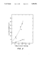
- FIG. 3 is a graph of real and imaginary parts of permittivity vs. tubule epoxy weight fraction. The measurements were made on rod samples placed in a microwave rectangular guide (post-in-waveguide). Multiple data points at the same weight fraction are both for measurements of different samples and for measurements at different locations along the length of a particular rod sample.
- the present invention is best understood by reference to the interaction of a tubule with an electric field E.
- the external field induces a dipole moment p in the tubule which can be expressed by
- ⁇ 0 is the permittivity of free space and ⁇ is the polarizability of the tubule.
- ⁇ is complex
- ⁇ R gives the in phase response and ⁇ I give the out of phase response of the tubule to the external field.
- ⁇ depends on the field frequency and on tubule geometry, orientation and conductivity.
- ⁇ m a magnetic polarizability
- ⁇ is, in general, complex. That ⁇ is complex results from the complex character of ⁇ in Eq. (7),
- V t is the total shell volume occupied by all the metal tubules
- ⁇ t and ⁇ are the respective densities of the metal and the matrix epoxy.
- ⁇ has a curved, rather than a linear, dependence on F, as seen in FIG. 2.
- the scattering cross section is several orders of magnitude smaller than the extinction cross section, hence the extinction cross section is very nearly equal to the absorption cross section.
- a more useful quantity is the attenuation length D defined through the relation,
- I the intensity of radiation at a distance x into the medium along the direction of propagation and I 0 is the intensity at the surface. Since the absorption plays the dominant role at microwave frequencies (scattering is negligible), the attenuation is primarily due to absorption. Therefore, A, the absorption coefficient per unit volume, is
- metallized lipid tubules of high aspect ratio can be used in the composites according to the present invention.
- metallized tubules useful in the present invention have aspect ratios of greater than twenty, preferably greater than 50, and most preferably greater than 150.
- the metal clad tubules will have an aspect ratio of 15 to 500, more often 50 to 150, and typically about 100, inclusive of the coating thickness.
- the lipid tubules useful in the present invention can be made and/or metallized by any process suitable to the production and/or metallization of lipid tubules having a high aspect ratio.
- These processes include, but are not limited to, the processes for producing a lipid tubule described in the Schnur et al '501 patent and the copending Schoen et al U.S. patent application Ser. Nos. 07/161,934, filed Feb. 29, 1988 (incorporated herein by reference) and 07/256,680, filed Sept. 16, 1988 (incorporated herein by reference) and the processes for making a lipid tubule and then metallizing that tubule described in Schnur '981 patent.
- metal coating used on metal clad lipid tubules can be used as the metal coating of the metal clad lipid tubules used in the present invention.
- Typical metal coatings include, but are not limited to, gold, iron, copper, permalloy (alloy of Ni and Fe), nickel, cobalt and a layered alloy of gold on nickel.
- the coating may be ferromagnetic or not depending on the end use desired for the composite.
- the matrix within which the tubules are aligned and held can be either a ceramic or a polymer such as an epoxy, a vinyl, an acrylamide or a wax. If the matrix is a ceramic, the tubules may be, for example, aligned within the ceramic matrix while the ceramic is in the sol gel state and the aligned sol gel then sintered for densification to provide a porous ceramic. If a polymer matrix is desired, the tubules may be added to the uncured polymer or polymer solution, the tubules aligned while within the uncured polymer or polymer solution, and the uncured polymer or polymer solution cured by conventional means. Depending on the rate at which the sintering or curing process occurs, the tubules can be aligned during the initial stages of the sintering or curing process, before viscosity of the matrix has increased sufficiently to prevent effective alignment.
- the viscosity of the matrix should be as little as possible, to permit alignment, but should be sufficient to maintain the metal clad lipid tubules in suspension.
- useful viscosities for particle alignment are in the range of about the viscosity of water to about the viscosity of heavy maple syrup.
- the intensity of the electromagnetic effects of the metal clad tubules increases with the load fraction of the metal clad tubules within the matrix. Because the metal clad lipid tubules are thixotropic, the loading fraction of the tubules within the matrix can also influence the matrix viscosity prior to sintering or curing. Therefore, with a polymer matrix, for example, the metal clad lipid tubules preferably constitute, depending on the end use envisioned, about 0.5 to about 50 weight percent of the combined weight of the metal clad lipid tubule and uncured polymer.
- the preferred loading fraction of tubules within a ceramic matrix will depend on the viscosity of the sol gel containing the matrix and any factors, such as the liquid medium and any suspending agents, which influence the same, as well as the desired end use. Because the metal clad lipid tubules are hollow, they will exert little mechanical influence on the bulk properties of the cured or sintered product.
- the metal clad lipid tubules can be easily aligned, depending on the nature of the cladding, within an electrical field, a magnetic field or a flow field. While only lipid tubules with a ferromagnetic cladding can be aligned within a magnetic field, any metal clad lipid tubule can be aligned within an electrical field or a flow field.
- the prepolymer (uncured polymer) or sol gel and lipid tubules are mixed and placed within a mold.
- the mold is held between two faces of a magnet and a magnetic field is applied between the faces to align the tubules.
- the mixture of aligned tubules and prepolymer or sol gel is allowed to set and the set polymer or ceramic containing the aligned tubules is released from the mold by conventional means.
- the magnetic field applied to align the tubules within the matrix is about 50 to 1000 Gauss, preferably about 200 to 800 Gauss, and most preferably about 450 to 650, and typically about 500 Gauss.
- the ferromagnetic metal clad lipid tubules will align with the magnetic field in the area corresponding to their location within the field.
- the prepolymer (uncured polymer) or sol gel and lipid tubules are mixed and placed within a mold.
- the mold is held within an electrical field generated by any suitable means, such as between the plates of a capacitor.
- the metal clad lipid tubules will orient along the electric field lines in the area corresponding to their location within the field.
- the prepolymer or sol gel and lipid tubules are passed through a conduit during curing or sintering so as to generate a flow field of the desired shape.
- the metal clad lipid tubules will orient along the flow field lines in the area corresponding to their location within the aligning field.
- the tubules By appropriately positioning the sample containing the metal clad lipid tubules relative to the aligning field, the tubules, since they align with the field where they are located, can be aligned in a geometry which will provide a final product having useful directional focusing or filtering capabilities, such as a spatially tunable lens or filter.
- 90% or more of the metal clad lipid tubules will be aligned within 5° of the direction of the field at their location during alignment. More preferably, 90% or more of the metal clad lipid tubules will be aligned within 2° of the direction of the field at their location during alignment.
- Specimens were prepared by mixing permalloy coated tubules (mean length 30 mm, metal coating ⁇ 1000 ⁇ ) with epoxy (74% Epon 815 epoxy+26% Ancamide 507B curing agent) and cast into rods and sheets using silicon rubber molds. The initial tubule-epoxy mixture was diluted by adding more epoxy to obtain lower concentrations of tubules in the medium.
- the rod samples (diameter 1.5 mm and length 10 cm) were allowed to cure overnight in a magnetic field ( ⁇ 100 Gauss) in order to orient the tubules along the field axis.
- Microscopic examination of the samples revealed a high degree of alignment along the rod axis for low loadings of tubules.
- the tubule/epoxy composite was highly viscous and the alignment of the tubules was poor. Some clustering and nesting of the tubules were also observed.
- Another microwave technique known as the "post-in-waveguide” method is useful for determination of permittivities of filamentary samples.
- the technique is specially suitable for samples with large dielectric constants or high losses.
- samples must present a sufficient impedance mismatch to the waveguide to affect the reflection and transmission coefficients in a measurable way.
- the same rod-shaped samples are used as above, inserted into the sample chamber through a small hole drilled in the waveguide.
- the data analysis consists of computing the complex transmission and reflection coefficients (the S-parameters) for the post geometry using a T shaped equivalent impedance network.
- the cavity measurement setup was simple, consisting of a microwave source (a Hewlett Packard 8341A microwave synthesized sweeper), a waveguide fixture and a detector (Pacific Measurements 1038-N10 Network Analyzer).
- the waveguide fixture consisted of a coax-to-waveguide adapter, an isolator (to prevent standing waves in the waveguide), a directional coupler (to tap off the microwave signal reflected from the cavity) and a rectangular TE 103 mode cavity with a variable coupling to the waveguide.
- the synthesizer was swept through the cavity resonance and the signal was detected by a diode attached to the network analyzer.
- the center frequency and frequency half width were determined by a processing digital oscilloscope, and passed to an IBM XT computer. The complex permittivity was then calculated.
- Post-in-waveguide measurements were carried out by attaching a straight section of waveguide to a Hewlett Packard 8510 Vector Network Analyzer. The complex S-parameters versus frequency were then processed on a VAX computer to yield the permittivity of the sample versus frequency.
- Equations (16) and (17) The theoretical values of ⁇ as calculated from Equations (16) and (17) depend on the choice of several parameters. These parameters are the radiation frequency, tubule length and radius, tubule conductivity, tubule loading fraction, and the medium's dielectric constant. While most of these parameters are known or easily measurable, two parameters present special problems. One is the tubule length which spans a wide range and the other is the conductivity of the metal coating.
- the length distribution of the tubules has been previously studied and reported in Georger et al, J. Am. Chem. Soc. 109, 6169 (1987), the entirety of which is incorporated herein by reference. Using this length distribution, one can calculate the contributions of the tubules to the bulk permittivity weighted according to their statistical distribution in out specimens.
- the conductivity of the thin metal coating is hard to measure directly.
- Several attempts at a direct measurement of resistivity on a single tubule were unsuccessful.
- These lithographically defined metal strips still much larger than the tubules, typically 20-80 ⁇ m wide, 800 ⁇ m long, and about 0.1 ⁇ m thick, were coated onto substrates by using an electroless process similar to that employed to metallize the tubules.
- Microprobes observed under a microscope, were used to determine the resistance of the thin strips of copper as a function of length.
- the measurements on these metal strips gave a conductivity of about 10 5 /ohm-meter (i.e. about 50-fold lower than the bulk value for copper). The conductivity was observed to deteriorate in time, presumably due to corrosion.
- the results of the post-in-waveguide experiments appear in FIG. 3.
- the permittivity values for the samples with the higher tubule loadings are somewhat higher than the values measured by the cavity resonance techniques.
- the reason for this discrepancy is that the cavity method is most accurate for low loss, low dielectric samples that do not destroy the resonance condition. Consequently, the cavity technique is ill suited for lossy samples as the measurement is only possible by greatly increasing the coupling between the cavity and the waveguide. Therefore, the post-in-waveguide technique is more reliable for samples with high losses or a high dielectric constant. Similarly, the low loss, low dielectric samples are most reliably measured in a cavity.
- a simple and direct way of measuring the dielectric constant of the tubule-epoxy composite is to measure the capacitance of a parallel plate capacitor with the sample serving as the dielectric medium.
- a commercial capacitance bridge was used to measure the capacitance of a well isolated parallel plate capacitor consisting of a sheet of tubule-epoxy composite sandwiched between two conducting sheets of aluminum foils and held together by teflon cap plates.
- the results show a dielectric constant of ⁇ R ⁇ 7 and a loss tangent ( ⁇ I / ⁇ R ) of about 0.02.
- the loss tangent increased, as expected from theory, having the value 0.03 at a frequency of 1 MHz.
- the flow casting process aligns the tubules randomly in the plane of the sheets. So in the capacitance measurement, the field E is nearly always perpendicular to the tubule.
- the measurement thus reflects mainly the dielectric constant of the epoxy matrix, which has been measured to be about 3.
- Metallized tubules with large aspect ratios present a rare opportunity for creation of novel materials with extremely anisotropic electromagnetic properties.
- Classical electrodynamics appears to account well for the observed data on a dilute dispersion of tubules.
- the highest tubule/epoxy weight fraction in our experimental samples was 0.4, which translates to a volume fraction of 0.15.
- a higher loading fraction produces a tubule-epoxy paste which does not flow well and is hard to mold.
- Different prepolymer solutions or ceramic sol-gels may permit higher loading fractions.
- the theoretical treatment assumes no tubule-tubule interaction and thus is only valid for dilute composites. Further, the theory is based on the assumption that the wavelength of the radiation is large compared with the tubule dimensions, i.e., the entire tubule sees the same field. This assumption is certainly valid at microwave frequencies, but breaks down when the wavelength of radiation becomes comparable to tubule length.
- tubule-epoxy composite to possess certain desirable properties. For example, to reduce the dielectric losses one needs to increase the conductivity of the coating. All other parameters being equal, a tenfold increase in conductivity reduces ⁇ I by a factor of ten, but leaves ⁇ R unaffected. Thus, the loss ratio ⁇ I / ⁇ R is reduced by a factor of ten.
- Such a dielectric medium with very low losses and a large anisotropic dielectric constant has great promise in technological applications, for instance in the development of capacitors, and waveguides.
- the tubule-epoxy composite is predicted to maintain its high dielectric constant at frequencies as high as 100 GHz. Though the loss ratio increases linearly with frequency, the real part of the dielectric constant remains essentially unaffected. This proves to be a real virtue compared with many currently available dielectrics which quickly lose their large permittivities as the frequency is increased beyond 10 8 Hz. The reason is that molecular dipoles are the source of high permittivity in common dielectrics whereas in the tubule system, one uses the conduction electrons to create charge separation. Electrons respond far more quickly to an external field than molecular dipoles.
- the tubule length to diameter ratio (aspect ratio) has the most dramatic effect on dielectric properties of the tubule-epoxy composites.
- Eqs. (9), (10), (16) and (17) doubling the tubule length enhances by a factor of about 3, while ⁇ I increases by a factor of 12, thus increasing the loss ratio by 4.
- modest increases in the tubule length could dramatically increase the dielectric constant beyond the current value of ⁇ 50, while increases in the metal conductivity could reduce the loss tangent.
Landscapes
- Physics & Mathematics (AREA)
- Electromagnetism (AREA)
- Engineering & Computer Science (AREA)
- Microelectronics & Electronic Packaging (AREA)
- Measurement Of Resistance Or Impedance (AREA)
Abstract
Description
p=αε.sub.0 E (1)
α=α.sub.R +iα.sub.I. (2)
P=(κ-1)ε.sub.0 E (4)
κ=κ.sub.R +iκ.sub.I.
α.sub.R =v/L (11)
α.sub.I =v/L.sup.2 κ.sub.I (12)
α.sub.R =Lκ.sub.I α.sub.I. (13)
ε.sub.R =ε.sub.m +Nα.sub.R, (16)
ε.sub.I =Nα.sub.1. (17)
F=v.sub.t ρ.sub.t /(V.sub.t ρ.sub.t +(1-V.sub.t)ρ.sub.e) (18)
S=k.sup.4 |α|.sup.2 /6π, (19)
Ω=kα.sub.1. (20)
I(x)=I.sub.0 e.sup.-x/D, (21)
A=D.sup.-1 =NΩ=Nkα.sub.I. (22)
Claims (27)
Priority Applications (1)
| Application Number | Priority Date | Filing Date | Title |
|---|---|---|---|
| US07/575,749 US5096551A (en) | 1990-08-31 | 1990-08-31 | Metallized tubule-based artificial dielectric |
Applications Claiming Priority (1)
| Application Number | Priority Date | Filing Date | Title |
|---|---|---|---|
| US07/575,749 US5096551A (en) | 1990-08-31 | 1990-08-31 | Metallized tubule-based artificial dielectric |
Publications (1)
| Publication Number | Publication Date |
|---|---|
| US5096551A true US5096551A (en) | 1992-03-17 |
Family
ID=24301549
Family Applications (1)
| Application Number | Title | Priority Date | Filing Date |
|---|---|---|---|
| US07/575,749 Expired - Lifetime US5096551A (en) | 1990-08-31 | 1990-08-31 | Metallized tubule-based artificial dielectric |
Country Status (1)
| Country | Link |
|---|---|
| US (1) | US5096551A (en) |
Cited By (22)
| Publication number | Priority date | Publication date | Assignee | Title |
|---|---|---|---|---|
| US5786040A (en) * | 1994-08-25 | 1998-07-28 | The University Of Iowa Research Foundation | Methods for coating surfaces with magnetic composites exhibiting distinct flux properties |
| US5814414A (en) * | 1992-04-27 | 1998-09-29 | The United States Of America As Represented By The Secretary Of The Navy | High aspect ratio metal microstructures and method for preparing the same |
| US5817221A (en) * | 1994-08-25 | 1998-10-06 | University Of Iowa Research Foundation | Composites formed using magnetizable material, a catalyst and an electron conductor |
| US5871625A (en) * | 1994-08-25 | 1999-02-16 | University Of Iowa Research Foundation | Magnetic composites for improved electrolysis |
| US6355166B1 (en) | 1994-08-25 | 2002-03-12 | The University Of Iowa Research Foundation | Magnetically enhanced composite materials and methods for making and using the same |
| US6376393B1 (en) * | 1997-05-16 | 2002-04-23 | Harris Corporation | Method for producing anisotropic dielectric layer and devices including same |
| US6514575B2 (en) | 1994-08-25 | 2003-02-04 | University Of Iowa Research Foundation | Magnetic composites exhibiting distinct flux properties due to gradient interfaces |
| US6660193B2 (en) | 2001-10-03 | 2003-12-09 | Andrew Corporation | Method of manufacturing a lens for microwave frequencies |
| US20030232223A1 (en) * | 1994-08-25 | 2003-12-18 | Johna Leddy | Methods for forming magnetically modified electrodes and articles produced thereby |
| US20040026253A1 (en) * | 1994-08-25 | 2004-02-12 | Johna Leddy | Methods for forming magnetically modified electrodes and articles produced thereby |
| US6913828B2 (en) | 1999-11-30 | 2005-07-05 | The United States Of America As Represented By The Secretary Of The Navy | Production of hollow metal microcylinders from lipids |
| US20050213187A1 (en) * | 1994-08-25 | 2005-09-29 | University Of Iowa Research Foundation | Methods for forming magnetically modified electrodes and articles produced thereby |
| US20050233199A1 (en) * | 2004-04-05 | 2005-10-20 | Xingwu Wang | Hydrogen storage apparatus comprised of halloysite |
| US20050285073A1 (en) * | 2004-06-25 | 2005-12-29 | Harpreet Singh | Permanently linked, rigid, magnetic chains |
| US20060076354A1 (en) * | 2004-10-07 | 2006-04-13 | Lanzafame John F | Hydrogen storage apparatus |
| US20060163160A1 (en) * | 2005-01-25 | 2006-07-27 | Weiner Michael L | Halloysite microtubule processes, structures, and compositions |
| US20060196764A1 (en) * | 2003-01-30 | 2006-09-07 | Geo-Centers, Inc. | Microwave-attenuating composite materials, methods for preparing the same, intermediates for preparing the same, devices containing the same, methods of preparing such a device, and methods of attenuating microwaves |
| US7400490B2 (en) | 2005-01-25 | 2008-07-15 | Naturalnano Research, Inc. | Ultracapacitors comprised of mineral microtubules |
| US7550963B1 (en) * | 1996-09-20 | 2009-06-23 | The Regents Of The University Of California | Analytical scanning evanescent microwave microscope and control stage |
| US20110147073A1 (en) * | 2007-09-20 | 2011-06-23 | Nitto Denko Corporation | Electromagnetic radiation absorber and method for absorbing electromagnetic radiation |
| US20110165405A1 (en) * | 2004-09-16 | 2011-07-07 | Nanosys, Inc. | Continuously variable graded artificial dielectrics using nanostructures |
| US8558311B2 (en) | 2004-09-16 | 2013-10-15 | Nanosys, Inc. | Dielectrics using substantially longitudinally oriented insulated conductive wires |
-
1990
- 1990-08-31 US US07/575,749 patent/US5096551A/en not_active Expired - Lifetime
Non-Patent Citations (4)
| Title |
|---|
| Rudolph, A. S. et al., Technological Development of Lipid Based Tubule Mistructures (1988), pp. 305-320. |
| Rudolph, A. S. et al., Technological Development of Lipid Based Tubule Microstructures (1988), pp. 305 320. * |
| Schoen et al., Order in Diacetylenic Microstructures (1987), pp. 357 366. * |
| Schoen et al., Order in Diacetylenic Microstructures (1987), pp. 357-366. |
Cited By (45)
| Publication number | Priority date | Publication date | Assignee | Title |
|---|---|---|---|---|
| US5814414A (en) * | 1992-04-27 | 1998-09-29 | The United States Of America As Represented By The Secretary Of The Navy | High aspect ratio metal microstructures and method for preparing the same |
| US20100173068A1 (en) * | 1994-05-26 | 2010-07-08 | University Of Iowa Research Foundation | Methods for forming magnetically modified electrodes and articles produced thereby |
| US6949179B2 (en) | 1994-08-25 | 2005-09-27 | University Of Iowa Research Foundation | Methods for forming magnetically modified electrodes and articles produced thereby |
| US20100225987A1 (en) * | 1994-08-25 | 2010-09-09 | The University Of Lowa Research Foundation | Methods for forming magnetically modified electrodes and articles produced thereby |
| US5928804A (en) * | 1994-08-25 | 1999-07-27 | The University Of Iowa Research Foundation | Fuel cells incorporating magnetic composites having distinct flux properties |
| US5981095A (en) * | 1994-08-25 | 1999-11-09 | University Of Iowa Research Foundation | Magnetic composites and methods for improved electrolysis |
| US6001248A (en) * | 1994-08-25 | 1999-12-14 | The University Of Iowa Research Foundation | Gradient interface magnetic composites and systems therefor |
| US5786040A (en) * | 1994-08-25 | 1998-07-28 | The University Of Iowa Research Foundation | Methods for coating surfaces with magnetic composites exhibiting distinct flux properties |
| US6303242B1 (en) | 1994-08-25 | 2001-10-16 | The University Of Iowa Research Foundation | Gradient interface magnetic composites and methods therefor |
| US6355166B1 (en) | 1994-08-25 | 2002-03-12 | The University Of Iowa Research Foundation | Magnetically enhanced composite materials and methods for making and using the same |
| US6375885B1 (en) | 1994-08-25 | 2002-04-23 | The University Of Iowa Research Foundation | Methods for coating surfaces with magnetic composites exhibiting distinct flux properties |
| US6207313B1 (en) | 1994-08-25 | 2001-03-27 | The University Of Iowa Research Foundation | Magnetic composites and methods for improved electrolysis |
| US6479176B2 (en) | 1994-08-25 | 2002-11-12 | University Of Iowa Research Foundation | Gradient interface magnetic composites and methods therefor |
| US6514575B2 (en) | 1994-08-25 | 2003-02-04 | University Of Iowa Research Foundation | Magnetic composites exhibiting distinct flux properties due to gradient interfaces |
| US20100178537A1 (en) * | 1994-08-25 | 2010-07-15 | University Of Iowa Research Foundation | Methods for forming magnetically modified electrodes and articles produced thereby |
| US20030232223A1 (en) * | 1994-08-25 | 2003-12-18 | Johna Leddy | Methods for forming magnetically modified electrodes and articles produced thereby |
| US20040026253A1 (en) * | 1994-08-25 | 2004-02-12 | Johna Leddy | Methods for forming magnetically modified electrodes and articles produced thereby |
| US5817221A (en) * | 1994-08-25 | 1998-10-06 | University Of Iowa Research Foundation | Composites formed using magnetizable material, a catalyst and an electron conductor |
| US7709115B2 (en) | 1994-08-25 | 2010-05-04 | University Of Iowa Research Foundation | Methods for forming magnetically modified electrodes and articles produced thereby |
| US20050213187A1 (en) * | 1994-08-25 | 2005-09-29 | University Of Iowa Research Foundation | Methods for forming magnetically modified electrodes and articles produced thereby |
| US5871625A (en) * | 1994-08-25 | 1999-02-16 | University Of Iowa Research Foundation | Magnetic composites for improved electrolysis |
| US7550963B1 (en) * | 1996-09-20 | 2009-06-23 | The Regents Of The University Of California | Analytical scanning evanescent microwave microscope and control stage |
| US8358141B2 (en) | 1996-09-20 | 2013-01-22 | The Regents Of The University Of California | Analytical scanning evanescent microwave microscope and control stage |
| US20090302866A1 (en) * | 1996-09-20 | 2009-12-10 | The Regents Of The University Of California | Analytical scanning evanescent microwave microscope and control stage |
| US6376393B1 (en) * | 1997-05-16 | 2002-04-23 | Harris Corporation | Method for producing anisotropic dielectric layer and devices including same |
| US6913828B2 (en) | 1999-11-30 | 2005-07-05 | The United States Of America As Represented By The Secretary Of The Navy | Production of hollow metal microcylinders from lipids |
| US6660193B2 (en) | 2001-10-03 | 2003-12-09 | Andrew Corporation | Method of manufacturing a lens for microwave frequencies |
| US20090176028A1 (en) * | 2003-01-30 | 2009-07-09 | Science Application International Corporation | Microwave-attenuating composite materials, methods for preparing the same, intermediates for preparing the same, devices containing the same, methods of preparing such a device, and methods of attentuating microwaves |
| US20060196764A1 (en) * | 2003-01-30 | 2006-09-07 | Geo-Centers, Inc. | Microwave-attenuating composite materials, methods for preparing the same, intermediates for preparing the same, devices containing the same, methods of preparing such a device, and methods of attenuating microwaves |
| US7125476B2 (en) * | 2003-01-30 | 2006-10-24 | The United States Of America As Represented By The Secretary Of The Navy | Microwave-attenuating composite materials, methods for preparing the same, intermediates for preparing the same, devices containing the same, methods of preparing such a device, and methods of attenuating microwaves |
| US7829153B2 (en) * | 2003-01-30 | 2010-11-09 | Science Applications International Corporation | Microwave-attenuating composite materials, methods for preparing the same, intermediates for preparing the same, devices containing the same, methods of preparing such a device, and methods of attenuating microwaves |
| US20050233199A1 (en) * | 2004-04-05 | 2005-10-20 | Xingwu Wang | Hydrogen storage apparatus comprised of halloysite |
| US7425232B2 (en) | 2004-04-05 | 2008-09-16 | Naturalnano Research, Inc. | Hydrogen storage apparatus comprised of halloysite |
| US20050285073A1 (en) * | 2004-06-25 | 2005-12-29 | Harpreet Singh | Permanently linked, rigid, magnetic chains |
| US7332101B2 (en) * | 2004-06-25 | 2008-02-19 | Massachusetts Institute Of Technology | Permanently linked, rigid, magnetic chains |
| WO2006088487A3 (en) * | 2004-06-25 | 2006-12-28 | Massachusetts Inst Technology | Permanently linked, magnetic chains |
| US8089152B2 (en) | 2004-09-16 | 2012-01-03 | Nanosys, Inc. | Continuously variable graded artificial dielectrics using nanostructures |
| US20110165405A1 (en) * | 2004-09-16 | 2011-07-07 | Nanosys, Inc. | Continuously variable graded artificial dielectrics using nanostructures |
| US8558311B2 (en) | 2004-09-16 | 2013-10-15 | Nanosys, Inc. | Dielectrics using substantially longitudinally oriented insulated conductive wires |
| US20060076354A1 (en) * | 2004-10-07 | 2006-04-13 | Lanzafame John F | Hydrogen storage apparatus |
| US20100171081A1 (en) * | 2005-01-25 | 2010-07-08 | Naturalnano Research, Inc. | Ultracapacitors comprised of mineral microtubules |
| US7679883B2 (en) | 2005-01-25 | 2010-03-16 | Naturalnano Research, Inc. | Ultracapacitors comprised of mineral microtubules |
| US7400490B2 (en) | 2005-01-25 | 2008-07-15 | Naturalnano Research, Inc. | Ultracapacitors comprised of mineral microtubules |
| US20060163160A1 (en) * | 2005-01-25 | 2006-07-27 | Weiner Michael L | Halloysite microtubule processes, structures, and compositions |
| US20110147073A1 (en) * | 2007-09-20 | 2011-06-23 | Nitto Denko Corporation | Electromagnetic radiation absorber and method for absorbing electromagnetic radiation |
Similar Documents
| Publication | Publication Date | Title |
|---|---|---|
| US5096551A (en) | Metallized tubule-based artificial dielectric | |
| Lagarkov et al. | Dielectric properties of fiber-filled composites | |
| Matitsine et al. | Shift of resonance frequency of long conducting fibers embedded in a composite | |
| Gao et al. | Quantitative microwave near-field microscopy of dielectric properties | |
| Lagarkov et al. | Resonance properties of bi-helix media at microwaves | |
| US7794629B2 (en) | Composite materials | |
| Cory | Chiral devices-an overview of canonical problems | |
| Guire et al. | Influence of chirality on the reflection of EM waves by planar dielectric slabs | |
| Behroozi et al. | Interaction of metallized tubules with electromagnetic radiation | |
| Hoang et al. | Lightweight electromagnetic shields using optimized polyaniline composites in the microwave band | |
| Yang et al. | Basic blocks for high-frequency interconnects: Theory and experiment | |
| Kelly et al. | Wave‐guide measurements in the microwave region on metal powders suspended in paraffin wax | |
| Jacquart et al. | Permeability measurement on composites made of oriented metallic wires from 0.1 to 18 GHz | |
| Marathe et al. | A compact dual, triple band resonators for negative permittivity metamaterial | |
| JPH02500869A (en) | Methods of manufacturing and uses of materials that can be predetermined with respect to dielectric, pyroelectric and/or magnetic properties | |
| CN1066539C (en) | Test method of non-metallic material microwave dielectric property and its application equipment | |
| Chiu et al. | Scattering from an advanced composite cylindrical shell | |
| US6677762B1 (en) | Method for determining the permeability of a magnetic material by coaxial line perturbation | |
| Chang et al. | Full-wave analysis of multilayer coplanar lines | |
| Chen et al. | Characterization of coupled cylindrical microstrip lines mounted inside a ground cylinder | |
| Kadera et al. | Effective Complex Permittivity Measurement of 3D Printed Artificial Dielectric Substrate Based on a Cross Unit Cell | |
| Acher | Frequency response engineering of magnetic composite materials | |
| Harvey | Parallel-plate transmission systems for microwave frequencies | |
| Ding et al. | Mixture properties of carbon fibre composite materials for electronics shielding in systems packaging | |
| Boifot | Broadband method for measuring dielectric constant of liquids using an automatic network analyser |
Legal Events
| Date | Code | Title | Description |
|---|---|---|---|
| AS | Assignment |
Owner name: NAVY, THE UNITED STATES OF AMERICA AS REPRESENTED Free format text: ASSIGNMENT OF ASSIGNORS INTEREST.;ASSIGNORS:SCHOEN, PAUL E. JR.;SCHNUR, JOEL M.;REEL/FRAME:005456/0515 Effective date: 19900829 |
|
| REMI | Maintenance fee reminder mailed | ||
| REIN | Reinstatement after maintenance fee payment confirmed | ||
| FP | Lapsed due to failure to pay maintenance fee |
Effective date: 19960320 |
|
| FEPP | Fee payment procedure |
Free format text: PETITION RELATED TO MAINTENANCE FEES FILED (ORIGINAL EVENT CODE: PMFP); ENTITY STATUS OF PATENT OWNER: LARGE ENTITY |
|
| FEPP | Fee payment procedure |
Free format text: PETITION RELATED TO MAINTENANCE FEES GRANTED (ORIGINAL EVENT CODE: PMFG); ENTITY STATUS OF PATENT OWNER: LARGE ENTITY |
|
| FPAY | Fee payment |
Year of fee payment: 4 |
|
| SULP | Surcharge for late payment | ||
| STCF | Information on status: patent grant |
Free format text: PATENTED CASE |
|
| PRDP | Patent reinstated due to the acceptance of a late maintenance fee |
Effective date: 19970926 |
|
| FPAY | Fee payment |
Year of fee payment: 8 |
|
| FPAY | Fee payment |
Year of fee payment: 12 |