US5094779A - Method for measuring and testing the efficiency of gas mask filters using monodispersed aerosols - Google Patents
Method for measuring and testing the efficiency of gas mask filters using monodispersed aerosols Download PDFInfo
- Publication number
- US5094779A US5094779A US07/636,165 US63616590A US5094779A US 5094779 A US5094779 A US 5094779A US 63616590 A US63616590 A US 63616590A US 5094779 A US5094779 A US 5094779A
- Authority
- US
- United States
- Prior art keywords
- aerosol
- testing
- filter
- test
- air
- Prior art date
- Legal status (The legal status is an assumption and is not a legal conclusion. Google has not performed a legal analysis and makes no representation as to the accuracy of the status listed.)
- Expired - Fee Related
Links
- 239000000443 aerosol Substances 0.000 title claims description 45
- 238000000034 method Methods 0.000 title claims description 16
- 238000012360 testing method Methods 0.000 title description 29
- 238000010998 test method Methods 0.000 claims abstract description 4
- 229940093629 isopropyl isostearate Drugs 0.000 claims abstract description 3
- NEOZOXKVMDBOSG-UHFFFAOYSA-N propan-2-yl 16-methylheptadecanoate Chemical compound CC(C)CCCCCCCCCCCCCCC(=O)OC(C)C NEOZOXKVMDBOSG-UHFFFAOYSA-N 0.000 claims abstract description 3
- 150000003839 salts Chemical class 0.000 claims abstract 2
- 239000000203 mixture Substances 0.000 description 17
- 239000000779 smoke Substances 0.000 description 17
- 239000002245 particle Substances 0.000 description 14
- FAPWRFPIFSIZLT-UHFFFAOYSA-M Sodium chloride Chemical compound [Na+].[Cl-] FAPWRFPIFSIZLT-UHFFFAOYSA-M 0.000 description 12
- 238000009834 vaporization Methods 0.000 description 12
- 230000008016 vaporization Effects 0.000 description 12
- 238000009826 distribution Methods 0.000 description 9
- 239000000463 material Substances 0.000 description 9
- 238000010790 dilution Methods 0.000 description 8
- 239000012895 dilution Substances 0.000 description 8
- 230000032683 aging Effects 0.000 description 6
- 239000011780 sodium chloride Substances 0.000 description 6
- 238000002663 nebulization Methods 0.000 description 4
- MQIUGAXCHLFZKX-UHFFFAOYSA-N Di-n-octyl phthalate Natural products CCCCCCCCOC(=O)C1=CC=CC=C1C(=O)OCCCCCCCC MQIUGAXCHLFZKX-UHFFFAOYSA-N 0.000 description 3
- BJQHLKABXJIVAM-UHFFFAOYSA-N bis(2-ethylhexyl) phthalate Chemical compound CCCCC(CC)COC(=O)C1=CC=CC=C1C(=O)OCC(CC)CCCC BJQHLKABXJIVAM-UHFFFAOYSA-N 0.000 description 3
- 238000005259 measurement Methods 0.000 description 3
- 230000035515 penetration Effects 0.000 description 3
- 238000000149 argon plasma sintering Methods 0.000 description 2
- 230000001276 controlling effect Effects 0.000 description 2
- 238000013461 design Methods 0.000 description 2
- 238000010586 diagram Methods 0.000 description 2
- 208000007345 glycogen storage disease Diseases 0.000 description 2
- 238000002156 mixing Methods 0.000 description 2
- 230000001681 protective effect Effects 0.000 description 2
- 108091006629 SLC13A2 Proteins 0.000 description 1
- 238000004458 analytical method Methods 0.000 description 1
- 238000000889 atomisation Methods 0.000 description 1
- 238000009835 boiling Methods 0.000 description 1
- 230000000711 cancerogenic effect Effects 0.000 description 1
- 231100000315 carcinogenic Toxicity 0.000 description 1
- 238000009833 condensation Methods 0.000 description 1
- 230000005494 condensation Effects 0.000 description 1
- 230000003247 decreasing effect Effects 0.000 description 1
- 239000002274 desiccant Substances 0.000 description 1
- 238000007865 diluting Methods 0.000 description 1
- 229910001651 emery Inorganic materials 0.000 description 1
- 238000005516 engineering process Methods 0.000 description 1
- 150000002148 esters Chemical class 0.000 description 1
- 239000004816 latex Substances 0.000 description 1
- 229920000126 latex Polymers 0.000 description 1
- 239000007788 liquid Substances 0.000 description 1
- 231100000053 low toxicity Toxicity 0.000 description 1
- 238000004519 manufacturing process Methods 0.000 description 1
- 238000012544 monitoring process Methods 0.000 description 1
- 230000000149 penetrating effect Effects 0.000 description 1
- 238000004886 process control Methods 0.000 description 1
- 238000010791 quenching Methods 0.000 description 1
- 230000001105 regulatory effect Effects 0.000 description 1
- 238000011160 research Methods 0.000 description 1
- 239000000243 solution Substances 0.000 description 1
- 238000005507 spraying Methods 0.000 description 1
- 239000000126 substance Substances 0.000 description 1
- 231100000606 suspected carcinogen Toxicity 0.000 description 1
- 238000005979 thermal decomposition reaction Methods 0.000 description 1
- 238000011144 upstream manufacturing Methods 0.000 description 1
Images

Classifications
-
- A—HUMAN NECESSITIES
- A62—LIFE-SAVING; FIRE-FIGHTING
- A62B—DEVICES, APPARATUS OR METHODS FOR LIFE-SAVING
- A62B27/00—Methods or devices for testing respiratory or breathing apparatus for high altitudes
-
- G—PHYSICS
- G01—MEASURING; TESTING
- G01N—INVESTIGATING OR ANALYSING MATERIALS BY DETERMINING THEIR CHEMICAL OR PHYSICAL PROPERTIES
- G01N15/00—Investigating characteristics of particles; Investigating permeability, pore-volume or surface-area of porous materials
- G01N15/08—Investigating permeability, pore-volume, or surface area of porous materials
- G01N2015/084—Testing filters
Definitions
- the present invention relates to a method for the generation of a nearly monodispersed aerosol in a filter-testing penetrometer machine.
- the present invention is superior to the previous method in that it employs a candidate material as a replacement for dioctyl phthalate, which is a suspected carcinogen.
- the candidate material or composition utilized in this invention is Emerest 2310 manufactured by Henkel Corporation, Emery Group, 11501 Northlake Drive, P. O. Box 429557, Cincinnati Ohio 45249.
- the composition has been identified as a thermally stable material of low toxicity.
- the composition is isopropyl isostearate which is an ester.
- a new generation of smoke penetrometers has been developed which utilize the generation of cold smokes or cold aerosols. Cold smokes or aerosols can be generated by the process of cold atomization/vaporization, and recondensation of a liquid. This process produces a nearly monodispersed smoke. Penetrometer machines are used to test U.S. Army masks, respirators, filters and other personnel protection equipment.
- FIG. 1 is a diagram showing flow paths for aerosol generation, measurement, and filter test flows in the penetrometer.
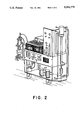
- FIG. 2 is a sketch of the penetrometer with physical locations of the various system components, controls and indicators.
- FIG. 1 shows schematically the flow diagram of the penetrometer machine.
- Fig. 2 shows an illustration of the same machine, with labels designating important components.
- the Los Alamos Monodispersed Aerosol Prototype Penetrometer was developed at the Los Alamos National Laboratory during a research program funded by the Product Assurance Directorate of the U.S. Army Armament, Munitions and Chemical Command.
- the purpose of the program was to design, build, and test a prototype respirator filter test penetrometer with improved performance, utilizing improved compositions.
- the improved penetrometer was to incorporate state-of-the-art principles, components, technology, and procedures for the task of testing respirator filters.
- a stable test removal aerosol having a diameter of 0.2-0.3 ⁇ m expressed either as the geometric means diameter (GMD), or as the count means diameter (CMD), and/or a geometric standard deviation (GSD) of 1.30 or less, and concentration 25 ⁇ 10 mg/m 3 .
- GMD geometric means diameter
- CMD count means diameter
- GSD geometric standard deviation
- the Los Alamos generator utilizes a fine polydisperse aerosol to initiate production of a monodispersed aerosol.
- the polydisperse aerosol is produced by room temperature nebulization of our composition in a generator using a Laskin nozzle. This allows vaporization of small particles at temperatures below the material boiling point, decreasing the potential for thermal decomposition.
- an aerosol is generated from a diluted sodium chloride solution. This sodium chloride aerosol mixes with the composition aerosol stream which then enters the vaporization tube. The NaCl droplets dry to very small nuclei particles.
- the candidate material vapor is condensed by the addition of cooler diluting air while the NaCl aerosol provides a source of excess nuclei to initiate and control condensing candidate particle growth.
- a nearly monodispered aerosol of particles in the submicron size range can be generated.
- the recondensed aerosol passes into an aging chamber to allow uniform mixing of the aerosol. From the aging chamber a sample of the aerosol is piped to a "LAS-X" laser aerosol spectrometer.
- the LAS-X is manufactured by Particle Measuring Systems, Inc., 1855 South 57th Court, Boulder, Colo. 80301.
- the LAS-X measures particle size frequency over a range of contiguous class intervals from which average particle size can be computed expressed as count mean diameter (CMD) and also width of particle distribution, expressed as geometric standard deviation (GSD).
- CMD count mean diameter
- GSD geometric standard deviation
- Aerosol from the aging chamber is also piped to the filter test chuck for filter efficiency analysis.
- the chuck is a pneumatically-operated device which holds and seals the filter canister to be tested. Aerosol passing through the filter flows through a light scattering chamber upstream and downstream of the filter to measure the percent of the original aerosol psssing through the filter, i.e., the filter's efficiency.
- compressed house air for smoke generation enters the instrument through an electrically controlled solenoid valve (1, FIG. 1).
- the compressed air is regulated to 40 psi. before passing through a desiccant air dryer (2, Fig. 1).
- a 0.2 micron absolute HEPA filter removes any particulates from the air stream (3, FIG. 1).
- a portion of the air stream flows to two regulators (4,5, FIG. 2) which control flows to the two aerosol generators (6,7, FIG. 1). Air streams from the two generators merge before entering the vaporization tube (8, FIG. 1).
- compressed air is also supplied to a regulator which lowers the air pressure to 15 psi. (9, FIG. 1).
- the flow separates into two air streams, the bypass air and the dilution or quench air.
- the rate of flow of the bypass air is controlled by a flowmeter (10, FIG. 1) and is adjustable from 0-25 LPM.
- the bypass air enters the vaporization tube opposite the outlet from the aerosal generators.
- the primary function of the bypass air is to cool the vaporation tube while no aerosol is being generated; it also serves to dilute and increase aerosol flow through the vaporization tube.
- the dilution air flow-meter (11, FIG. 1) controls the flow of the dilution air, flow may be varied between 0-100 LPM.
- the dilution air merges with the vaporized aerosol just after leaving the vaporization tube.
- the dilution air controls the rate of condensation and concentration of the aerosol.
- thermocouple (12, FIG. 1) monitors the temperature of the aerosol in the vaporization tube.
- An Omega 4000 series temperature controller (13, FIG. 1) displays the vaporation tube temperature while controlling voltage output to electric heat tape (14, FIG. l) which is employed to heat the vaporization tube.
- Temperature of the aerosol can be controlled from 25°-200° C.
- the aerosol flows to an aging chamber (15, FIG. 1) where recondensation and uniform mixing is accomplished.
- a small fraction of the candidate material smoke is drawn from the outlet of the aging chamber through a in-line capillary dilution system (16, FIG. 1).
- a magnehelic gauge (17, FIG. 1) indicates the pressure differential across the dilution system.
- the LAS-X laser aerosol spectrometer samples the diluted smoke, and transfers particle distribution data to the HP-85.
- the Hewlett Packard Microcomputer (18, FIG. 1) calculates and prints the aerosol's statistical data. This system measures and prints smoke GMD and GSD.
- Smoke from the capillary diluter that is not used by the LAS-X is filtered via a in-line HEPA filter (19, FIG. 1). Flow of sample smoke is controlled by the sample control valve (20, FIG. 1). Sample air is then exhausted via the house vacuum source.
- Compressed air for operation of the chuck is controlled by a pressure regulator (27, FIG. 1) set to 30 psi.
- Smoke for filter testing is drawn from the aging chamber through the chuck (21, FIG. 1).
- Filter resistance is measured by a magnehelic gauge (22, FIG. 1).
- Smoke concentration penetrating the test filter is measured downstream of the test chuck by a light scattering photometer (23, FIG. 1). The photometer indicates percent penetration through the test filter.
- Smoke remaining in the sample flow is filtered by a in-line HEPA filter within the photometer.
- Smoke remaining in the test air is removed by an in-line HEPA filter (24, FIG. 1).
- Test air flow is controlled by a flowmeter (25, FIG. 1).
- Test air is exhausted via a house vacuum source.
- Smoke generated which is not used for filter testing is cleared of particulate a HEPA filter (26, FIG. 1).
- the geometric mean diameter (GMD), in micrometers ( ⁇ m), of the aerosol must lie between 0.18 ⁇ m and 0.33 ⁇ m. This is the count or number mean of the distribution. That is, all particles in all size ranges are counted, and a distribution is drawn showing the total number of particles in all ranges (a histogram). From this, a mean size is determined.
- the geometric standard deviation (GSD) of the distribution must not exceed 1.30.
- the smoke concentration at the test chuck where filter canisters are inserted must be 25 md/m 3 plus or minus 10mg/m 3 . Concentrations that are too high can be reduced by process control adjustments.
Landscapes
- Health & Medical Sciences (AREA)
- Pulmonology (AREA)
- General Health & Medical Sciences (AREA)
- Business, Economics & Management (AREA)
- Emergency Management (AREA)
- Sampling And Sample Adjustment (AREA)
Abstract
Description
______________________________________
Our composition nebulization pressure
                        2.25   psi
 (5. FIG. 1)
NaC1 nebulization pressure
                        6.0    psi
 (4, FIG. 1)
Vaporization tube temperature
                        145    C.
(13, FIG. 1)
Aerosol dilution air flow
                        60     LPM
(11, FIG. 1)
Bypass air              0      LPM
(10, FIG. 1)
______________________________________
Claims (4)
Priority Applications (1)
| Application Number | Priority Date | Filing Date | Title |
|---|---|---|---|
| US07/636,165 US5094779A (en) | 1990-12-31 | 1990-12-31 | Method for measuring and testing the efficiency of gas mask filters using monodispersed aerosols |
Applications Claiming Priority (1)
| Application Number | Priority Date | Filing Date | Title |
|---|---|---|---|
| US07/636,165 US5094779A (en) | 1990-12-31 | 1990-12-31 | Method for measuring and testing the efficiency of gas mask filters using monodispersed aerosols |
Publications (1)
| Publication Number | Publication Date |
|---|---|
| US5094779A true US5094779A (en) | 1992-03-10 |
Family
ID=24550704
Family Applications (1)
| Application Number | Title | Priority Date | Filing Date |
|---|---|---|---|
| US07/636,165 Expired - Fee Related US5094779A (en) | 1990-12-31 | 1990-12-31 | Method for measuring and testing the efficiency of gas mask filters using monodispersed aerosols |
Country Status (1)
| Country | Link |
|---|---|
| US (1) | US5094779A (en) |
Cited By (6)
| Publication number | Priority date | Publication date | Assignee | Title |
|---|---|---|---|---|
| WO2007031772A1 (en) * | 2005-09-15 | 2007-03-22 | The Secretary Of State For Defence | Apparatus and methods for dilution |
| US7415864B1 (en) * | 2006-08-31 | 2008-08-26 | The United States Of America As Represented By The Secretary Of The Army | Orifice test device for protective mask testers |
| US7614280B1 (en) * | 2006-03-06 | 2009-11-10 | The United States Of America As Represented By The Secretary Of The Army | Quantitative fit test system and method for assessing respirator biological fit factors |
| CN101131345B (en) * | 2006-09-22 | 2010-07-21 | 北京清能创新科技有限公司 | Detecting device for mask filtration efficiency and resistance |
| CN111929213A (en) * | 2020-07-11 | 2020-11-13 | 黎明职业大学 | Gauze mask filters check out test set |
| US20230228665A1 (en) * | 2020-07-02 | 2023-07-20 | Philip Morris Products S.A. | Test chamber apparatus for assessing filter media |
Citations (6)
| Publication number | Priority date | Publication date | Assignee | Title |
|---|---|---|---|---|
| USH185H (en) * | 1985-11-25 | 1987-01-06 | The United States Of America As Represented By The Secretary Of The Army | Respirator perimetry device |
| USH267H (en) * | 1984-12-18 | 1987-05-05 | The United States Of America As Represented By The Secretary Of The Army | Method and apparatus for improved gas mask and filter test penetrometer |
| US4914957A (en) * | 1988-04-15 | 1990-04-10 | Westinghouse Electric Corp. | Leak test adaptor apparatus for facilitating leak testing face mask respirators |
| US4917830A (en) * | 1988-09-19 | 1990-04-17 | The United States Of America As Represented By The United States Department Of Energy | Monodisperse aerosol generator |
| US4963289A (en) * | 1988-09-19 | 1990-10-16 | The United States Of America As Represented By The United States Department Of Energy | Method for producing monodisperse aerosols |
| USH863H (en) * | 1990-07-24 | 1991-01-01 | The United States Of America As Represented By The Secretary Of The Army | Chemical protective hood |
-
1990
- 1990-12-31 US US07/636,165 patent/US5094779A/en not_active Expired - Fee Related
Patent Citations (6)
| Publication number | Priority date | Publication date | Assignee | Title |
|---|---|---|---|---|
| USH267H (en) * | 1984-12-18 | 1987-05-05 | The United States Of America As Represented By The Secretary Of The Army | Method and apparatus for improved gas mask and filter test penetrometer |
| USH185H (en) * | 1985-11-25 | 1987-01-06 | The United States Of America As Represented By The Secretary Of The Army | Respirator perimetry device |
| US4914957A (en) * | 1988-04-15 | 1990-04-10 | Westinghouse Electric Corp. | Leak test adaptor apparatus for facilitating leak testing face mask respirators |
| US4917830A (en) * | 1988-09-19 | 1990-04-17 | The United States Of America As Represented By The United States Department Of Energy | Monodisperse aerosol generator |
| US4963289A (en) * | 1988-09-19 | 1990-10-16 | The United States Of America As Represented By The United States Department Of Energy | Method for producing monodisperse aerosols |
| USH863H (en) * | 1990-07-24 | 1991-01-01 | The United States Of America As Represented By The Secretary Of The Army | Chemical protective hood |
Cited By (14)
| Publication number | Priority date | Publication date | Assignee | Title |
|---|---|---|---|---|
| GB2445683B (en) * | 2005-09-15 | 2010-10-13 | Secr Defence | Apparatus and methods for dilution |
| US7913535B2 (en) | 2005-09-15 | 2011-03-29 | The Secretary Of State For Defence In Her Britannic Majesty's Government Of The United Kingdom Of Great Britain And Northern Ireland | Apparatus and methods for dilution |
| US20080202196A1 (en) * | 2005-09-15 | 2008-08-28 | The Secretary Of State For Defence | Apparatus and Methods For Dilution |
| WO2007031772A1 (en) * | 2005-09-15 | 2007-03-22 | The Secretary Of State For Defence | Apparatus and methods for dilution |
| GB2445683A (en) * | 2005-09-15 | 2008-07-16 | Secr Defence | Apparatus and methods for dilution |
| US7614280B1 (en) * | 2006-03-06 | 2009-11-10 | The United States Of America As Represented By The Secretary Of The Army | Quantitative fit test system and method for assessing respirator biological fit factors |
| US8151630B1 (en) * | 2006-03-06 | 2012-04-10 | The United States Of America As Represented By The Secretary Of The Army | Quantitative fit test system and method for assessing respirator biological fit factors |
| US7415864B1 (en) * | 2006-08-31 | 2008-08-26 | The United States Of America As Represented By The Secretary Of The Army | Orifice test device for protective mask testers |
| CN101131345B (en) * | 2006-09-22 | 2010-07-21 | 北京清能创新科技有限公司 | Detecting device for mask filtration efficiency and resistance |
| JP2023531900A (en) * | 2020-07-02 | 2023-07-26 | フィリップ・モーリス・プロダクツ・ソシエテ・アノニム | Test Chamber Apparatus for Evaluating Filter Media |
| US20230228665A1 (en) * | 2020-07-02 | 2023-07-20 | Philip Morris Products S.A. | Test chamber apparatus for assessing filter media |
| US12265009B2 (en) * | 2020-07-02 | 2025-04-01 | Philip Morris Products S.A. | Test chamber apparatus for assessing filter media |
| CN111929213B (en) * | 2020-07-11 | 2022-08-23 | 黎明职业大学 | Gauze mask filters check out test set |
| CN111929213A (en) * | 2020-07-11 | 2020-11-13 | 黎明职业大学 | Gauze mask filters check out test set |
Similar Documents
| Publication | Publication Date | Title |
|---|---|---|
| US4917830A (en) | Monodisperse aerosol generator | |
| US4963289A (en) | Method for producing monodisperse aerosols | |
| Wang et al. | Toward standardized test methods to determine the effectiveness of filtration media against airborne nanoparticles | |
| Japuntich et al. | A comparison of two nano-sized particle air filtration tests in the diameter range of 10 to 400 nanometers | |
| Porstendörfer et al. | Experimental determination of the attachment coefficients of atoms and ions on monodisperse aerosols | |
| Kinney et al. | Use of the electrostatic classification method to size 0.1 μm SRM particles—a feasibility study | |
| Liu et al. | Efficiency of membrane and nuclepore filters for submicrometer aerosols | |
| US5076965A (en) | Method of generating mono dispersed aerosols for non-destructive gas mask filter testing | |
| US6532797B1 (en) | Barrier test apparatus and method | |
| US5094779A (en) | Method for measuring and testing the efficiency of gas mask filters using monodispersed aerosols | |
| US5059351A (en) | Method of testing the efficiency of gas mask filters using monodispersed aerosols | |
| JPH04216439A (en) | Method and apparatus for calibrating particle counter | |
| US5059352A (en) | Method for the generation of monodispersed aerosols for filter testing | |
| Middlebrook et al. | On the purity of laboratory-generated sulfuric acid droplets and ambient particles studied by laser mass spectrometry | |
| US5080829A (en) | Method of measuring the efficiency of gas mask filters, respirators and other personnel protective equipment | |
| Liu et al. | Respirator leak detection by ultrafine aerosols: a predictive model and experimental study | |
| Mitchell | Aerosol generation for instrument calibration | |
| US5059348A (en) | Method for measuring the efficiency of gas mask filters | |
| Horton et al. | Characterization of a condensation-type monodisperse aerosol generator (MAGE) | |
| US5059353A (en) | Method for testing the efficiency of gas mask filters using monodispersed aerosols | |
| Mulholland et al. | Response of smoke detectors to monodisperse aerosols | |
| US5059350A (en) | Method of testing the efficiency of gas mask filters using poly-alpha olefin aerosol mixtures | |
| US5059349A (en) | Method of measuring the efficiency of gas mask filters using monodispersed aerosols | |
| USH1040H (en) | Method for measuring filter efficiency | |
| US5087389A (en) | Method of measuring the efficiency of gas mask filters using non-toxic mono dispersed aerosols |
Legal Events
| Date | Code | Title | Description |
|---|---|---|---|
| AS | Assignment |
Owner name: UNITED STATES OF AMERICA, THE, AS REPRESENTED BY T Free format text: ASSIGNMENT OF ASSIGNORS INTEREST. SUBJECT TO LICENSE RECITED;ASSIGNORS:CARLON, HUGH R.;GUELTA, MARK A.;REEL/FRAME:005665/0259;SIGNING DATES FROM 19910102 TO 19910110 Owner name: OPTIMETRICS, INC. Free format text: ASSIGNMENT OF ASSIGNORS INTEREST.;ASSIGNOR:GERBER, BERNARD V.;REEL/FRAME:005665/0262 Effective date: 19910103 Owner name: UNITED STATES OF AMERICA, THE, AS REPRESENTED BY T Free format text: ASSIGNMENT OF ASSIGNORS INTEREST. SUBJECT TO LICENSE RECITED;ASSIGNOR:OPTIMETRICS, INC.;REEL/FRAME:005665/0267 Effective date: 19910124 |
|
| FPAY | Fee payment |
Year of fee payment: 4 |
|
| FPAY | Fee payment |
Year of fee payment: 8 |
|
| REMI | Maintenance fee reminder mailed | ||
| LAPS | Lapse for failure to pay maintenance fees | ||
| FP | Lapsed due to failure to pay maintenance fee |
Effective date: 20040310 |
|
| STCH | Information on status: patent discontinuation |
Free format text: PATENT EXPIRED DUE TO NONPAYMENT OF MAINTENANCE FEES UNDER 37 CFR 1.362 |