US5089796A - Earth leakage trip indicator - Google Patents
Earth leakage trip indicator Download PDFInfo
- Publication number
- US5089796A US5089796A US07/584,975 US58497590A US5089796A US 5089796 A US5089796 A US 5089796A US 58497590 A US58497590 A US 58497590A US 5089796 A US5089796 A US 5089796A
- Authority
- US
- United States
- Prior art keywords
- tripping
- circuit breaker
- plunger
- drive rod
- breaker
- Prior art date
- Legal status (The legal status is an assumption and is not a legal conclusion. Google has not performed a legal analysis and makes no representation as to the accuracy of the status listed.)
- Expired - Lifetime
Links
- 238000001514 detection method Methods 0.000 claims abstract description 18
- 230000007935 neutral effect Effects 0.000 claims description 6
- 230000000694 effects Effects 0.000 claims description 4
- 230000000295 complement effect Effects 0.000 claims description 3
- 238000005192 partition Methods 0.000 abstract description 3
- CWYNVVGOOAEACU-UHFFFAOYSA-N Fe2+ Chemical compound [Fe+2] CWYNVVGOOAEACU-UHFFFAOYSA-N 0.000 description 3
- 239000000463 material Substances 0.000 description 3
- 229920003023 plastic Polymers 0.000 description 3
- 239000004033 plastic Substances 0.000 description 3
- 230000001681 protective effect Effects 0.000 description 3
- 238000010276 construction Methods 0.000 description 2
- 239000002184 metal Substances 0.000 description 2
- 239000004020 conductor Substances 0.000 description 1
- 238000004519 manufacturing process Methods 0.000 description 1
- 230000000452 restraining effect Effects 0.000 description 1
Images


Classifications
-
- H—ELECTRICITY
- H01—ELECTRIC ELEMENTS
- H01H—ELECTRIC SWITCHES; RELAYS; SELECTORS; EMERGENCY PROTECTIVE DEVICES
- H01H83/00—Protective switches, e.g. circuit-breaking switches, or protective relays operated by abnormal electrical conditions otherwise than solely by excess current
- H01H83/20—Protective switches, e.g. circuit-breaking switches, or protective relays operated by abnormal electrical conditions otherwise than solely by excess current operated by excess current as well as by some other abnormal electrical condition
- H01H83/22—Protective switches, e.g. circuit-breaking switches, or protective relays operated by abnormal electrical conditions otherwise than solely by excess current operated by excess current as well as by some other abnormal electrical condition the other condition being imbalance of two or more currents or voltages
-
- H—ELECTRICITY
- H01—ELECTRIC ELEMENTS
- H01H—ELECTRIC SWITCHES; RELAYS; SELECTORS; EMERGENCY PROTECTIVE DEVICES
- H01H71/00—Details of the protective switches or relays covered by groups H01H73/00 - H01H83/00
- H01H71/04—Means for indicating condition of the switching device
- H01H2071/048—Means for indicating condition of the switching device containing non-mechanical switch position sensor, e.g. HALL sensor
Definitions
- the invention relates to circuit breakers and in particular to circuit breakers of the type having both over-current and earth leakage protection, commonly referred to as residual current circuit breakers (RCCB's).
- RRCB's residual current circuit breakers
- Over-current protective devices have limitations such as delay in operation in situations where there is a relatively high earth loop impedance. Further, over-current protective devices do not detect earth fault currents below their operating current, which currents in certain circumstances may constitute a fire hazard. Accordingly, there is an increasing demand for protective devices providing both over-current and earth leakage protection.
- the invention provides a circuit breaker for use in a system having line, neutral and ground leads, comprising:
- a breaker assembly in said housing for making and breaking an electrical connection between a movable contact and a stationary contact
- the operating handle is movable to an additional position other than an off or on position to indicate when the breaker assembly has been tripped by said additional tripping mechanism.
- the additional position of said handle is intermediate the on and off positions.
- said additional tripping mechanism includes a residual current detection circuit and the additional position of the handle indicates when the breaker assembly has been tripped by a residual current fault.
- said over-current sensing means includes a coil and an armature core in the coil.
- the armature core has an axial bore extending therethrough; and the additional tripping mechanism comprises:
- plunger means mounted within the axial bore of the armature core
- an actuating device for controlling the movement of said plunger means from a non-tripping position to a tripping position
- said plunger means being independently movable through the axial bore in the armature core when moving between the non-tripping and tripping positions;
- the circuit breaker is a residual current circuit breaker and includes a residual current detection circuit for detection of a residual current in the system, and wherein said actuating device comprises a residual current actuating device for controlling the movement of said plunger means between a non-tripping position and a tripping position when a residual current fault is detected by said detection circuit.
- the actuating device comprises a drive rod which is movable upon detection of a residual current fault between a non-tripping position and a tripping position in which the drive rod engages and drives said plunger means into the tripping position; means for biasing or urging the drive rod into a tripping position; and means for retaining the drive rod in a non-tripping position.
- the retaining means comprises a permanent magnet to hold the drive rod in the non-tripping position and an electromagnet to neutralize the effect of the permanent magnet on the drive rod upon detection of a residual current fault.
- the biasing means comprise spring means for driving the drive rod into a tripping position engaging a plunger means.
- said reset means comprises a reset lever, interposed between the drive rod and a plunger means and a reset actuator for moving the lever to return the drive rod into the non-tripping position against the action of biasing means.
- the reset actuator comprises the circuit breaker operating handle which engages the reset lever when the handle is moved from the intermediate position to the off position with the contacts opened.
- the reset lever is pivotally mounted to the housing intermediate the ends thereof and comprises a first lever arm for engagement by the operating handle and a second lever arm interposed between the drive rod and plunger means.
- the reset lever is of substantially L shape in plan view.
- the plunger means comprises a single plunger rod extending through the bore in the armature core.
- the plunger rod is of non-ferrous, preferably plastics material.
- engagement means are provided intermediate the ends of the plunger rod for engagement by the armature core upon occurrence of an over-current fault, said engagement means being provided at substantially the mid point along the longitudinal axis of said plunger rod.
- said engagement means comprises a radially outwardly extending collar engagable in a complementary shaped recess in the armature core.
- the plunger rod is slidably mounted in a bushing provided in the coil at the end thereof remote from the armature core.
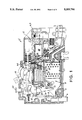
- FIG. 1 is a plan view of a circuit breaker according to the invention with the breaker in an on position
- FIG. 2 is a plan, partially cross-sectional view of the circuit breaker of FIG. 1,
- FIG. 3 is a cross-sectional view of a tripping portion of the circuit breaker in an on position
- FIG. 4 is a plan view of the tripping portion in a position just after a residual current fault is detected
- FIG. 5 is a plan view of the tripping portion in a position after tripping due to a residual current fault
- FIG. 6 is a plan view of the tripping portion in a position during reset
- FIG. 7 is a plan view of the tripping portion in a re-set position
- FIG. 8 is a plan view of a circuit breaker with the breaker tripped due to an over-current fault.
- the RCCB 1 comprises a housing 2 having a base and a cover which form a partition wall 3 which separates an over-current protection device 4 from an additional tripping means which in this case includes a residual current detection circuit 5.
- the RCCB 1 includes line and neutral supply terminals 6 and 7, line and neutral load terminals 8 and 9, and an earth terminal 10.
- the line supply terminal 6 is formed by a metal clip for both mechanical and electrical connection with a supply conductor.
- the line and neutral load terminals 8 and 9 are of the screw-type and are in side-by-side relationship in a side wall of the housing 2.
- the neutral supply terminal 7 and the earth terminal 10 are of the conventional cable type.
- the RCCB 1 includes a breaker assembly 15 which in this case is of the unitary type and includes a movable contact 16 for engagement with a fixed contact 17.
- the breaker assembly 15 also includes an operating handle 18 of conventional construction.
- the over-current protecting device 4 comprises a bi-metal element 19 abutting the breaker assembly 15 and an arc stack 27 of conventional construction.
- the device 4 also comprises a coil 20 having an armature 21 and having an armature core 22 which is biased into a non-tripping position illustrated in FIGS. 1 and 2 by a coil spring 26.
- An axial bore 23 extends through the core 22.
- An additional tripping mechanism which in this case operates in response to a residual current fault occurring, includes a single plunger rod 24 which extends through the partition wall 3, through the bore 23 and through a plunger bushing 25 to impact against a trip lever 28 of the breaker assembly 15 for moving the contact 16 away from the contact 17 to trip the breaker (see FIG. 2).
- the additional tripping mechanism includes the residual current detection circuit 5 and an actuating device 30 for controlling the movement of the plunger rod 24 between a non-tripping position and a tripping position when a residual current fault is detected by the detection circuit.
- Actuating device 30 comprises a drive rod 31 which is movable on detection of a residual current fault to engage and drive the plunger rod 24 through the bore 23 to trip the breaker.
- the drive rod 31 is biased into a forward or tripping position by a coil spring 32 wound around the rod 31.
- Retaining means for retaining the drive rod 31 in a non-tripping or retracted position comprises a magnetic assembly 35 comprising a permanent magnet to hold the drive rod 31 in a non-tripping position and an electromagnet to neutralize the effect of the permanent magnet on the drive rod 31 upon detection of a residual current fault by the circuit 5.
- the plunger rod 24 is in this case made of non-ferrous, preferably plastics material.
- the rod 24 includes an engagement mechanism in the form of a radially outwardly extending collar 50 which is engagable in a complementary shaped recess in the armature core 22.
- the collar 50 is provided substantially at the mid-point along the longitudinal axis of the plunger rod 24 so that the rod 24 is substantially symmetrical. Thus, on assembly, the rod 24 may be inserted into the bore 23 in either direction.
- a mechanism for re-setting of the plunger rod 24 to a non-tripping position comprises a reset lever 40 interposed between the drive rod 31 and plunger rod 34 and a reset actuator for moving the lever rod 40 to return the drive rod 31 into the non-tripping position against the action of the spring 32.
- the reset actuator comprises the circuit breaker operating handle 18 which includes an engagement surface 45 which engages against the reset lever 40 as will be described in more detail below.
- the reset lever 40 is pivotally mounted to the housing 2 intermediate the ends thereof, is of generally ⁇ L ⁇ shape in plan view and comprises a first arm 46 for engagement by the engagement surface 45 of the operating handle 18 and a second arm 47 interposed between the drive rod 31 and plunger rod 24.
- a test mechanism for checking the operation of the residual current tripping device comprises a test button 60 engagable against a lever 61 which is pivotally mounted to the housing 2 by a pivot pin 62.
- a spring 63 biases the lever 61 into the non-test position illustrated in FIGS. 1 and 2.
- the spring 63 is electrically connected to the coil 20 at one end and the lever 61 is arranged to move the other end of the spring 63 between a non-test position as illustrated in FIGS. 1 and 2 to a test position in contact with a push to test terminal 64.
- FIGS. 3 through 8 In use, and referring particularly to FIGS. 3 through 8 in the normal non-tripped position illustrated in FIGS. 1 and 3 the handle 18 is in an on position fully to the left hand side as viewed in orientation of the drawings, the drive rod 31 is retracted, the reset lever 40 is at right angles to the drive rod 31, the armature core 22 is retracted, the plunger rod 24 is retracted and the contacts 16, 17 are closed.
- the circuit breaker of the invention has an indicating mechanism to indicate to a user whether the breaker has tripped due to an over-current fault or for another reason, for example as described above, due to a residual current fault.
- the indicating mechanism is provided by operating the handle 18 and more particularly by virtue of the position of the handle 18.
- the handle has three positions namely an on or non-tripped position as illustrated in FIGS. 1, 2, 3, 4 and 7, an intermediate position as illustrated in FIG. 5 to which the handle travels only in the event of a residual current fault occurring, and a fully off position as illustrated in FIG. 8 to which the handle 18 travels in the event of an over-current fault.
- the position of the handle 18 in the event of a fault indicates to a user which type of fault--over-current or residual current--has occurred.
- Another advantage of the breaker of the invention is that because the plunger means is independently movable through the armature core it performs the function of tripping the breaker independently of the armature core. There is no magnetic interference between the trip mechanism via movement of the armature core in the event of an over-current fault and movement of the plunger means in the event of a residual current fault.
- the plunger means may be used in association with a position sensing means such as an auxiliary switch to give a remote indication of the closed or open status of the breaker.
- the position sensing means may detect the position of the contacts directly or indirectly by sensing the position of the plunger.
- Auxiliary and command devices either locally or remotely operated may be used as an alternative to the residual current detection circuit to provide a tripping signal in the event of a fault or test condition occurring.
- the actuating device comprises a solenoid and said device is remotely operable.
- position sensing means are provided for sensing the position of said plunger means.
- said position sensing means comprises switch means operated by the plunger means upon movement between the non-tripped and tripped position.
- the invention provides an RCCB which is relatively simple and is reliable in operation.
- the use of a separate drive rod 31 and impact rod 32 allows the choice of suitable materials, in this case a plastics impact rod and ferrous drive rod. Further, re-setting is relatively simple as a hand-controlled lever may be easily used.
Landscapes
- Breakers (AREA)
- Emergency Protection Circuit Devices (AREA)
- Testing Of Short-Circuits, Discontinuities, Leakage, Or Incorrect Line Connections (AREA)
Abstract
A residual current circuit breaker 1 has a partition wall 3 which separates an over-current protection device 4 from a residual current detection circuit 5. A plunger rod 24 extends through a bore 23 in the armature 21 of a coil 20 and is moved independently through the coil 20 to trip the breaker if a residual current is detected by the circuit 5. The plunger rod 24 is moved by a drive rod 31, the operation of which is controlled by a permanent magnet which retains the drive rod 31 retracted and an electromagnet which allows the drive rod 31 to drive forwardly under the action of a spring 32 in the event of a residual current being detected. The plunger rod 30 is reset by a reset lever 40 which is moved when an operating handle 18 of the breaker moves from a non-tripped to a tripped position upon tripping of the breaker.
Description
The invention relates to circuit breakers and in particular to circuit breakers of the type having both over-current and earth leakage protection, commonly referred to as residual current circuit breakers (RCCB's).
Over-current protective devices have limitations such as delay in operation in situations where there is a relatively high earth loop impedance. Further, over-current protective devices do not detect earth fault currents below their operating current, which currents in certain circumstances may constitute a fire hazard. Accordingly, there is an increasing demand for protective devices providing both over-current and earth leakage protection.
It is an object of the invention to provide a residual current circuit breaker which is reliable in operation and relatively simple to manufacture.
According to one aspect, the invention provides a circuit breaker for use in a system having line, neutral and ground leads, comprising:
a housing;
a breaker assembly in said housing for making and breaking an electrical connection between a movable contact and a stationary contact;
an operating handle for the breaker assembly;
means for sensing over-current and thereby tripping said breaker assembly;
an additional tripping mechanism for tripping of said breaker assembly; and
means for indicating when the breaker assembly has been tripped by the additional tripping mechanism.
In a particular preferred embodiment of the invention the operating handle is movable to an additional position other than an off or on position to indicate when the breaker assembly has been tripped by said additional tripping mechanism. In a preferred embodiment the additional position of said handle is intermediate the on and off positions.
Preferably said additional tripping mechanism includes a residual current detection circuit and the additional position of the handle indicates when the breaker assembly has been tripped by a residual current fault.
In one embodiment of the invention said over-current sensing means includes a coil and an armature core in the coil. The armature core has an axial bore extending therethrough; and the additional tripping mechanism comprises:
plunger means mounted within the axial bore of the armature core;
an actuating device for controlling the movement of said plunger means from a non-tripping position to a tripping position;
said plunger means being independently movable through the axial bore in the armature core when moving between the non-tripping and tripping positions; and
means for re-setting said plunger means to the non-tripping position.
In a particularly preferred aspect the circuit breaker is a residual current circuit breaker and includes a residual current detection circuit for detection of a residual current in the system, and wherein said actuating device comprises a residual current actuating device for controlling the movement of said plunger means between a non-tripping position and a tripping position when a residual current fault is detected by said detection circuit.
In one embodiment of the invention the actuating device comprises a drive rod which is movable upon detection of a residual current fault between a non-tripping position and a tripping position in which the drive rod engages and drives said plunger means into the tripping position; means for biasing or urging the drive rod into a tripping position; and means for retaining the drive rod in a non-tripping position.
Preferably the retaining means comprises a permanent magnet to hold the drive rod in the non-tripping position and an electromagnet to neutralize the effect of the permanent magnet on the drive rod upon detection of a residual current fault.
In one arrangement the biasing means comprise spring means for driving the drive rod into a tripping position engaging a plunger means.
Preferably said reset means comprises a reset lever, interposed between the drive rod and a plunger means and a reset actuator for moving the lever to return the drive rod into the non-tripping position against the action of biasing means. In this preferred arrangement the reset actuator comprises the circuit breaker operating handle which engages the reset lever when the handle is moved from the intermediate position to the off position with the contacts opened. The reset lever is pivotally mounted to the housing intermediate the ends thereof and comprises a first lever arm for engagement by the operating handle and a second lever arm interposed between the drive rod and plunger means. Typically the reset lever is of substantially L shape in plan view. Finally, the plunger means comprises a single plunger rod extending through the bore in the armature core. Preferably the plunger rod is of non-ferrous, preferably plastics material.
In one embodiment of the invention engagement means are provided intermediate the ends of the plunger rod for engagement by the armature core upon occurrence of an over-current fault, said engagement means being provided at substantially the mid point along the longitudinal axis of said plunger rod. In one arrangement said engagement means comprises a radially outwardly extending collar engagable in a complementary shaped recess in the armature core. The plunger rod is slidably mounted in a bushing provided in the coil at the end thereof remote from the armature core.
The invention will be more clearly understood from the following description of some preferred embodiments thereof given by way of example only with reference to the accompanying drawings in which:
FIG. 1 is a plan view of a circuit breaker according to the invention with the breaker in an on position,
FIG. 2 is a plan, partially cross-sectional view of the circuit breaker of FIG. 1,
FIG. 3 is a cross-sectional view of a tripping portion of the circuit breaker in an on position,
FIG. 4 is a plan view of the tripping portion in a position just after a residual current fault is detected,
FIG. 5 is a plan view of the tripping portion in a position after tripping due to a residual current fault,
FIG. 6 is a plan view of the tripping portion in a position during reset,
FIG. 7 is a plan view of the tripping portion in a re-set position, and
FIG. 8 is a plan view of a circuit breaker with the breaker tripped due to an over-current fault.
Referring to the drawings, and initially to FIGS. 1 through 3 there is illustrated a circuit breaker in this case a residual current circuit breaker (RCCB) according to the invention indicated generally by the reference numeral 1. The RCCB 1 comprises a housing 2 having a base and a cover which form a partition wall 3 which separates an over-current protection device 4 from an additional tripping means which in this case includes a residual current detection circuit 5. The RCCB 1 includes line and neutral supply terminals 6 and 7, line and neutral load terminals 8 and 9, and an earth terminal 10. In this case, the line supply terminal 6 is formed by a metal clip for both mechanical and electrical connection with a supply conductor. The line and neutral load terminals 8 and 9 are of the screw-type and are in side-by-side relationship in a side wall of the housing 2. The neutral supply terminal 7 and the earth terminal 10 are of the conventional cable type.
The RCCB 1 includes a breaker assembly 15 which in this case is of the unitary type and includes a movable contact 16 for engagement with a fixed contact 17. The breaker assembly 15 also includes an operating handle 18 of conventional construction. The over-current protecting device 4 comprises a bi-metal element 19 abutting the breaker assembly 15 and an arc stack 27 of conventional construction. The device 4 also comprises a coil 20 having an armature 21 and having an armature core 22 which is biased into a non-tripping position illustrated in FIGS. 1 and 2 by a coil spring 26. An axial bore 23 extends through the core 22.
An additional tripping mechanism which in this case operates in response to a residual current fault occurring, includes a single plunger rod 24 which extends through the partition wall 3, through the bore 23 and through a plunger bushing 25 to impact against a trip lever 28 of the breaker assembly 15 for moving the contact 16 away from the contact 17 to trip the breaker (see FIG. 2). The additional tripping mechanism includes the residual current detection circuit 5 and an actuating device 30 for controlling the movement of the plunger rod 24 between a non-tripping position and a tripping position when a residual current fault is detected by the detection circuit. Actuating device 30 comprises a drive rod 31 which is movable on detection of a residual current fault to engage and drive the plunger rod 24 through the bore 23 to trip the breaker. The drive rod 31 is biased into a forward or tripping position by a coil spring 32 wound around the rod 31. Retaining means for retaining the drive rod 31 in a non-tripping or retracted position comprises a magnetic assembly 35 comprising a permanent magnet to hold the drive rod 31 in a non-tripping position and an electromagnet to neutralize the effect of the permanent magnet on the drive rod 31 upon detection of a residual current fault by the circuit 5.
The plunger rod 24 is in this case made of non-ferrous, preferably plastics material. The rod 24 includes an engagement mechanism in the form of a radially outwardly extending collar 50 which is engagable in a complementary shaped recess in the armature core 22. The collar 50 is provided substantially at the mid-point along the longitudinal axis of the plunger rod 24 so that the rod 24 is substantially symmetrical. Thus, on assembly, the rod 24 may be inserted into the bore 23 in either direction.
A mechanism for re-setting of the plunger rod 24 to a non-tripping position comprises a reset lever 40 interposed between the drive rod 31 and plunger rod 34 and a reset actuator for moving the lever rod 40 to return the drive rod 31 into the non-tripping position against the action of the spring 32. In this case the reset actuator comprises the circuit breaker operating handle 18 which includes an engagement surface 45 which engages against the reset lever 40 as will be described in more detail below.
The reset lever 40 is pivotally mounted to the housing 2 intermediate the ends thereof, is of generally `L` shape in plan view and comprises a first arm 46 for engagement by the engagement surface 45 of the operating handle 18 and a second arm 47 interposed between the drive rod 31 and plunger rod 24.
A test mechanism for checking the operation of the residual current tripping device comprises a test button 60 engagable against a lever 61 which is pivotally mounted to the housing 2 by a pivot pin 62. A spring 63 biases the lever 61 into the non-test position illustrated in FIGS. 1 and 2. The spring 63 is electrically connected to the coil 20 at one end and the lever 61 is arranged to move the other end of the spring 63 between a non-test position as illustrated in FIGS. 1 and 2 to a test position in contact with a push to test terminal 64.
In use, and referring particularly to FIGS. 3 through 8 in the normal non-tripped position illustrated in FIGS. 1 and 3 the handle 18 is in an on position fully to the left hand side as viewed in orientation of the drawings, the drive rod 31 is retracted, the reset lever 40 is at right angles to the drive rod 31, the armature core 22 is retracted, the plunger rod 24 is retracted and the contacts 16, 17 are closed. In the event of a residual current fault being detected by the circuit 5 the electromagnet of the magnetic assembly 35 is activated to neutralize the effect of the permanent magnet restraining the drive rod 31, allowing the rod 31 to extend outwardly under the action of the spring 32, striking the lever arm 47 of the reset lever 40 forwardly about its pivot to strike the plunger rod 24 which moves independently through the bore 23 of the armature core 22 to strike the lever 28. This configuration is illustrated in FIG. 4. The striking of the lever 28 releases a spring which moves the contact 16 away from the contact 17 and the handle 18 is thrown into an intermediate position illustrated in FIG. 5 in which the engagement surface 45 engages but does not move the reset lever 40. This intermediate position of the handle 18 indicates that the breaker has tripped due to a residual current fault.
To reset the breaker after a residual current trip the handle 18 is first manually moved in the direction of the arrow X in FIG. 5 towards the off position illustrated in FIG. 6. During this movement the engagement surface 45 of the handle 18 strikes the arm 46 of the reset lever 40 as illustrated in FIG. 5, pivoting the lever 40 counter clockwise and thus pushing the arm 47 of the reset lever 40 against the plunger rod 31 driving it back into the magnetic assembly housing against the biasing of the spring 32. The plunger rod 24 is then free to move back through the bore into the reset position illustrated in FIG. 6. When the handle 18 is thrown back into the on position the additional tripping device is returned to the on position illustrated in FIGS. 1, 3, and 7.
Referring to FIG. 8 in the event of an over-current fault occurring the armature core 22 is drawn into the coil 20 against the biasing of the spring 26, the recess 51 of the core 22 engaging with the collar 50 on the plunger rod 24 to drive the plunger rod 24 forward through the coil 20 to trip the breaker by striking the lever 28. When the breaker is tripped in this way by an over-current fault the handle 18 moves to the off position illustrated in FIG. 8.
The circuit breaker of the invention has an indicating mechanism to indicate to a user whether the breaker has tripped due to an over-current fault or for another reason, for example as described above, due to a residual current fault. The indicating mechanism is provided by operating the handle 18 and more particularly by virtue of the position of the handle 18. The handle has three positions namely an on or non-tripped position as illustrated in FIGS. 1, 2, 3, 4 and 7, an intermediate position as illustrated in FIG. 5 to which the handle travels only in the event of a residual current fault occurring, and a fully off position as illustrated in FIG. 8 to which the handle 18 travels in the event of an over-current fault. Thus, the position of the handle 18 in the event of a fault indicates to a user which type of fault--over-current or residual current--has occurred. Another advantage of the breaker of the invention is that because the plunger means is independently movable through the armature core it performs the function of tripping the breaker independently of the armature core. There is no magnetic interference between the trip mechanism via movement of the armature core in the event of an over-current fault and movement of the plunger means in the event of a residual current fault. Further, the plunger means may be used in association with a position sensing means such as an auxiliary switch to give a remote indication of the closed or open status of the breaker. The position sensing means may detect the position of the contacts directly or indirectly by sensing the position of the plunger.
Auxiliary and command devices either locally or remotely operated may be used as an alternative to the residual current detection circuit to provide a tripping signal in the event of a fault or test condition occurring.
In an embodiment of the invention the actuating device comprises a solenoid and said device is remotely operable.
In one embodiment of the invention position sensing means are provided for sensing the position of said plunger means. Preferably said position sensing means comprises switch means operated by the plunger means upon movement between the non-tripped and tripped position.
It will be appreciated that the invention provides an RCCB which is relatively simple and is reliable in operation. The use of a separate drive rod 31 and impact rod 32 allows the choice of suitable materials, in this case a plastics impact rod and ferrous drive rod. Further, re-setting is relatively simple as a hand-controlled lever may be easily used.
Claims (15)
1. A circuit breaker for use in a system having line, neutral and ground leads, comprising:
a housing;
a breaker assembly in said housing for making and breaking an electrical connection between a movable contact and a stationary contact;
an operating handle, having an on position with said contacts closed, an off position with said contacts open and an intermediate position with said contacts open, for the breaker assembly;
means for sensing over-current and thereby tripping said breaker assembly;
an additional tripping mechanism for tripping said breaker assembly;
said breaker handle moving to said intermediate position for indicating when the breaker assembly has been tripped by said additional tripping mechanism;
said over-current sensing means including a coil and an armature core in said coil, the armature core having an axial bore extending therethrough, said additional tripping mechanism comprising;
plunger means mounted within the axial bore of the armature core;
an actuating device for controlling the movement of said plunger means from a non=tripping position to a tripping position;
said plunger means being independently movable through the axial bore in the armature core when moving between said non-tripping and said tripping position; and
means for re-setting said plunger means to said non-tripping position.
2. The circuit breaker as claimed in claim 1 further including a residual current detection circuit for detection of a residual current in the system, and wherein said actuating device comprises a residual current actuating device for controlling the movement of said plunger means between said non-tripping position and said tripping position when a residual current fault is detected by said detection circuit.
3. The circuit breaker as claimed in claim 2 wherein said residual current actuating device comprises a drive rod which is movable upon detection of a residual current fault between a first position and a second position in which said drive rod engages and drives said plunger means into said tripping position; means for biasing said drive rod into said second position; and means for retaining said drive rod in said first position.
4. The circuit breaker as claimed in claim 3 wherein said retaining means comprises a permanent magnet to hold said drive rod in said first position and an electromagnet to neutralize the effect of said permanent magnet on said drive rod upon detection of a residual current fault.
5. The circuit breaker as claimed in claim 3 wherein said biasing means comprise spring means for driving said drive rod into said second position.
6. The circuit breaker as claimed in claim 3 wherein said resetting means comprises a reset lever interposed between said drive rod and said plunger means and a reset actuator for moving said reset lever to return said drive rod to said first position against the action of said biasing means.
7. The circuit breaker as claimed in claim 6 wherein said reset actuator comprises said operating handle which engages said reset lever when said operating handle is moved from said intermediate position to said off position with said contacts open.
8. The circuit breaker as claimed in claim 7 wherein said reset lever is pivotally mounted to said housing intermediate the ends of said reset lever and comprises a first lever arm for engagement by said operating handle and a second lever arm interposed between said drive rod and said plunger means.
9. The circuit breaker as claimed in claim 8 wherein said reset lever is substantially L shaped.
10. The circuit breaker as claimed in said claim 1 wherein said plunger means includes a plunger rod and wherein engagement means are provided intermediate the ends of said plunger rod for engagement by said armature core upon occurrence of an over-current fault, said engagement means being provided substantially at the midpoint along the longitudinal axis of said plunger rod.
11. The circuit breaker as claimed in claim 10 wherein said engagement means comprises a radially outwardly extending collar engagable in a complementary shaped recess in said armature core.
12. The circuit breaker as claimed in claim 11 wherein said plunger rod is slidably mounted in a bushing provided in said coil at the end thereof remote from said armature core.
13. The circuit breaker as claimed in claim 1 wherein said actuating device comprises a solenoid, and said actuating device is remotely operable.
14. A circuit breaker as claimed in claim 1 wherein position sensing means are provided for sensing the position of said plunger means.
15. The circuit breaker as claimed in claim 14 wherein said position sensing means comprises switch means operated by said plunger means upon movement between said non-tripping and said tripping position.
Priority Applications (6)
| Application Number | Priority Date | Filing Date | Title |
|---|---|---|---|
| US07/584,975 US5089796A (en) | 1990-09-19 | 1990-09-19 | Earth leakage trip indicator |
| PCT/US1991/006772 WO1992005569A1 (en) | 1990-09-19 | 1991-09-18 | Earth leakage trip indicator |
| AU88770/91A AU635888B2 (en) | 1990-09-19 | 1991-09-18 | Earth leakage trip indicator |
| IE329391A IE66381B1 (en) | 1990-09-19 | 1991-09-19 | Earth leakage trip indicator |
| MX9101176A MX9101176A (en) | 1990-09-19 | 1991-09-19 | EARTH DISPERSION INDICATOR |
| GB9209320A GB2253306B (en) | 1990-09-19 | 1992-04-30 | Circuit breaker |
Applications Claiming Priority (1)
| Application Number | Priority Date | Filing Date | Title |
|---|---|---|---|
| US07/584,975 US5089796A (en) | 1990-09-19 | 1990-09-19 | Earth leakage trip indicator |
Publications (1)
| Publication Number | Publication Date |
|---|---|
| US5089796A true US5089796A (en) | 1992-02-18 |
Family
ID=24339531
Family Applications (1)
| Application Number | Title | Priority Date | Filing Date |
|---|---|---|---|
| US07/584,975 Expired - Lifetime US5089796A (en) | 1990-09-19 | 1990-09-19 | Earth leakage trip indicator |
Country Status (6)
| Country | Link |
|---|---|
| US (1) | US5089796A (en) |
| AU (1) | AU635888B2 (en) |
| GB (1) | GB2253306B (en) |
| IE (1) | IE66381B1 (en) |
| MX (1) | MX9101176A (en) |
| WO (1) | WO1992005569A1 (en) |
Cited By (35)
| Publication number | Priority date | Publication date | Assignee | Title |
|---|---|---|---|---|
| US5331301A (en) * | 1990-02-23 | 1994-07-19 | Square D Company | Circuit breaker |
| US5402093A (en) * | 1992-05-29 | 1995-03-28 | Thomas Magnete Gmbh | Electromagnet having an armature with an injection-molded guide or control rod |
| US5612659A (en) * | 1994-08-08 | 1997-03-18 | Quicksilver Engineering | Battery protecting circuit breaker |
| US6104266A (en) * | 1999-06-02 | 2000-08-15 | General Electric Company | Circuit breaker with trip indication arrangement |
| US6107902A (en) * | 1998-11-19 | 2000-08-22 | General Electric Company | Circuit breaker with visible trip indicator |
| US6128168A (en) * | 1998-01-14 | 2000-10-03 | General Electric Company | Circuit breaker with improved arc interruption function |
| US6232857B1 (en) | 1999-09-16 | 2001-05-15 | General Electric Company | Arc fault circuit breaker |
| US6239962B1 (en) | 1999-02-09 | 2001-05-29 | General Electric Company | ARC fault circuit breaker |
| US6246304B1 (en) | 1999-03-26 | 2001-06-12 | Airpax Corporation, Llc | Trip indicating circuit breaker |
| US6259340B1 (en) | 1999-05-10 | 2001-07-10 | General Electric Company | Circuit breaker with a dual test button mechanism |
| US6268989B1 (en) | 1998-12-11 | 2001-07-31 | General Electric Company | Residential load center with arcing fault protection |
| US6356426B1 (en) | 1999-07-19 | 2002-03-12 | General Electric Company | Residential circuit breaker with selectable current setting, load control and power line carrier signaling |
| US6407894B1 (en) | 1999-11-05 | 2002-06-18 | Siemens Energy & Automation, Inc. | Method and apparatus for differentially sensing ground fault and individual phases |
| US6466424B1 (en) | 1999-12-29 | 2002-10-15 | General Electric Company | Circuit protective device with temperature sensing |
| GB2386255A (en) * | 2002-03-04 | 2003-09-10 | Masterplug Ltd | Leakage current breaker |
| US6678137B1 (en) | 2000-08-04 | 2004-01-13 | General Electric Company | Temperature compensation circuit for an arc fault current interrupting circuit breaker |
| US20070126538A1 (en) * | 2003-05-29 | 2007-06-07 | Ping Liu | Electrical switch |
| US20070158171A1 (en) * | 2006-01-10 | 2007-07-12 | Siemens Energy & Automation, Inc. | Control module |
| US20070200652A1 (en) * | 2006-02-24 | 2007-08-30 | Eaton Corporation | Electrical switching apparatus and trip indicator therefor |
| US20090167468A1 (en) * | 2005-08-09 | 2009-07-02 | Moeller Gmbh | Electrical circuit breaker having a protective function |
| US20100264001A1 (en) * | 2009-04-15 | 2010-10-21 | Spitsberg Yuri C | Mechanism or resettable trip indicator mechanism for a circuit interrupter and circuit interrupter including the same |
| US20110147178A1 (en) * | 2009-12-22 | 2011-06-23 | Schneider Electric USA, Inc. | Electronic Miniature Circuit Breaker With Trip Indication Using The Breaker Tripping Function As The Feedback Mechanism |
| EP2506283A1 (en) * | 2011-03-30 | 2012-10-03 | General Electric Company | Compact residual current breaker with overcurrent protection |
| US20130162378A1 (en) * | 2011-12-22 | 2013-06-27 | Andre Borgwardt | Power circuit breaker |
| WO2013102933A3 (en) * | 2011-12-27 | 2013-10-10 | Larsen And Toubro Limited | Residual current circuit breaker with overcurrent protection (rcbo) with an improved neutral pole kinematic chain |
| EP2242077A3 (en) * | 2009-04-18 | 2013-10-30 | General Electric Company | Space allocation within a circuit breaker |
| EP2486578A4 (en) * | 2009-10-08 | 2014-08-06 | Pty Ltd Industrics | RCBO THREE-PHASE |
| US20140292452A1 (en) * | 2011-12-02 | 2014-10-02 | Siemens Aktiengellschaft | Switching-device tripping apparatus |
| EP2309528A4 (en) * | 2008-07-04 | 2014-11-26 | Hubei Shengjia Wiring Co Ltd | Breaker with short circuit self-locking function |
| CN106653500A (en) * | 2017-03-13 | 2017-05-10 | 新驰电气有限公司 | Integrated residual current operated circuit breaker with current leakage indication function |
| US20190074153A1 (en) * | 2017-09-07 | 2019-03-07 | Carling Technologies, Inc. | Circuit Interrupter With Status Indication |
| US10460897B2 (en) * | 2017-01-05 | 2019-10-29 | Lsis Co., Ltd. | Magnetic trip device for circuit breaker |
| US10522314B2 (en) * | 2017-03-15 | 2019-12-31 | Lsis Co., Ltd. | Magnetic trip device for circuit breaker |
| US20230326695A1 (en) * | 2022-04-07 | 2023-10-12 | Eaton Intelligent Power Limited | Shunt trip circuit interrupter |
| CN119517695A (en) * | 2023-08-22 | 2025-02-25 | 浙江正泰电器股份有限公司 | Tripping indication structure of circuit breaker and circuit breaker |
Families Citing this family (3)
| Publication number | Priority date | Publication date | Assignee | Title |
|---|---|---|---|---|
| IE71036B1 (en) * | 1990-02-23 | 1997-01-15 | Square D Co | A circuit breaker |
| US5192941A (en) * | 1991-05-29 | 1993-03-09 | Westinghouse Electric Corp. | Overcurrent trip switch |
| CN100472908C (en) * | 2006-06-20 | 2009-03-25 | 浙江正泰建筑电器有限公司 | Double magnetic control leakage protector |
Citations (5)
| Publication number | Priority date | Publication date | Assignee | Title |
|---|---|---|---|---|
| US3440579A (en) * | 1967-06-19 | 1969-04-22 | Gen Electric | Electric circuit breaker with overcurrent and ground fault protection |
| US3440580A (en) * | 1967-06-19 | 1969-04-22 | Gen Electric | Electrical protective device |
| US3470507A (en) * | 1966-11-05 | 1969-09-30 | Square D Co | Earth-leakage sensing circuit breaker |
| US4000444A (en) * | 1971-05-07 | 1976-12-28 | 3-M Company | Electric circuit breaker with ground fault protection |
| US4858056A (en) * | 1988-06-06 | 1989-08-15 | General Electric Company | Molded case circuit breaker actuator-accessory module |
Family Cites Families (2)
| Publication number | Priority date | Publication date | Assignee | Title |
|---|---|---|---|---|
| US3460579A (en) * | 1966-04-12 | 1969-08-12 | Robert A Clarkson | Insulated flexible sub-zero hose |
| JPH03210726A (en) * | 1990-01-12 | 1991-09-13 | Mitsubishi Electric Corp | Circuit breaker with wiring for electric leakage alarm function |
-
1990
- 1990-09-19 US US07/584,975 patent/US5089796A/en not_active Expired - Lifetime
-
1991
- 1991-09-18 WO PCT/US1991/006772 patent/WO1992005569A1/en not_active Ceased
- 1991-09-18 AU AU88770/91A patent/AU635888B2/en not_active Ceased
- 1991-09-19 IE IE329391A patent/IE66381B1/en not_active IP Right Cessation
- 1991-09-19 MX MX9101176A patent/MX9101176A/en unknown
-
1992
- 1992-04-30 GB GB9209320A patent/GB2253306B/en not_active Expired - Fee Related
Patent Citations (5)
| Publication number | Priority date | Publication date | Assignee | Title |
|---|---|---|---|---|
| US3470507A (en) * | 1966-11-05 | 1969-09-30 | Square D Co | Earth-leakage sensing circuit breaker |
| US3440579A (en) * | 1967-06-19 | 1969-04-22 | Gen Electric | Electric circuit breaker with overcurrent and ground fault protection |
| US3440580A (en) * | 1967-06-19 | 1969-04-22 | Gen Electric | Electrical protective device |
| US4000444A (en) * | 1971-05-07 | 1976-12-28 | 3-M Company | Electric circuit breaker with ground fault protection |
| US4858056A (en) * | 1988-06-06 | 1989-08-15 | General Electric Company | Molded case circuit breaker actuator-accessory module |
Cited By (47)
| Publication number | Priority date | Publication date | Assignee | Title |
|---|---|---|---|---|
| US5331301A (en) * | 1990-02-23 | 1994-07-19 | Square D Company | Circuit breaker |
| US5402093A (en) * | 1992-05-29 | 1995-03-28 | Thomas Magnete Gmbh | Electromagnet having an armature with an injection-molded guide or control rod |
| US5612659A (en) * | 1994-08-08 | 1997-03-18 | Quicksilver Engineering | Battery protecting circuit breaker |
| US6128168A (en) * | 1998-01-14 | 2000-10-03 | General Electric Company | Circuit breaker with improved arc interruption function |
| US6107902A (en) * | 1998-11-19 | 2000-08-22 | General Electric Company | Circuit breaker with visible trip indicator |
| US6268989B1 (en) | 1998-12-11 | 2001-07-31 | General Electric Company | Residential load center with arcing fault protection |
| US6239962B1 (en) | 1999-02-09 | 2001-05-29 | General Electric Company | ARC fault circuit breaker |
| US6246304B1 (en) | 1999-03-26 | 2001-06-12 | Airpax Corporation, Llc | Trip indicating circuit breaker |
| US6259340B1 (en) | 1999-05-10 | 2001-07-10 | General Electric Company | Circuit breaker with a dual test button mechanism |
| US6104266A (en) * | 1999-06-02 | 2000-08-15 | General Electric Company | Circuit breaker with trip indication arrangement |
| US6356426B1 (en) | 1999-07-19 | 2002-03-12 | General Electric Company | Residential circuit breaker with selectable current setting, load control and power line carrier signaling |
| US6232857B1 (en) | 1999-09-16 | 2001-05-15 | General Electric Company | Arc fault circuit breaker |
| US6407894B1 (en) | 1999-11-05 | 2002-06-18 | Siemens Energy & Automation, Inc. | Method and apparatus for differentially sensing ground fault and individual phases |
| US6466424B1 (en) | 1999-12-29 | 2002-10-15 | General Electric Company | Circuit protective device with temperature sensing |
| US6678137B1 (en) | 2000-08-04 | 2004-01-13 | General Electric Company | Temperature compensation circuit for an arc fault current interrupting circuit breaker |
| GB2386255A (en) * | 2002-03-04 | 2003-09-10 | Masterplug Ltd | Leakage current breaker |
| US20070126538A1 (en) * | 2003-05-29 | 2007-06-07 | Ping Liu | Electrical switch |
| US7623010B2 (en) * | 2003-05-29 | 2009-11-24 | Ping Liu | Electrical switch |
| US7733199B2 (en) * | 2005-08-09 | 2010-06-08 | Moeller Gmbh | Electrical circuit breaker having a protective function |
| US20090167468A1 (en) * | 2005-08-09 | 2009-07-02 | Moeller Gmbh | Electrical circuit breaker having a protective function |
| US7692112B2 (en) | 2006-01-10 | 2010-04-06 | Siemens Industry, Inc. | Control module |
| US20070158171A1 (en) * | 2006-01-10 | 2007-07-12 | Siemens Energy & Automation, Inc. | Control module |
| US20070200652A1 (en) * | 2006-02-24 | 2007-08-30 | Eaton Corporation | Electrical switching apparatus and trip indicator therefor |
| US7358838B2 (en) * | 2006-02-24 | 2008-04-15 | Eaton Corporation | Electrical switching apparatus and trip indicator therefor |
| EP2309528A4 (en) * | 2008-07-04 | 2014-11-26 | Hubei Shengjia Wiring Co Ltd | Breaker with short circuit self-locking function |
| US20100264001A1 (en) * | 2009-04-15 | 2010-10-21 | Spitsberg Yuri C | Mechanism or resettable trip indicator mechanism for a circuit interrupter and circuit interrupter including the same |
| US8053694B2 (en) * | 2009-04-15 | 2011-11-08 | Eaton Corporation | Mechanism or resettable trip indicator mechanism for a circuit interrupter and circuit interrupter including the same |
| EP2242077A3 (en) * | 2009-04-18 | 2013-10-30 | General Electric Company | Space allocation within a circuit breaker |
| EP2486578A4 (en) * | 2009-10-08 | 2014-08-06 | Pty Ltd Industrics | RCBO THREE-PHASE |
| AU2010305324B2 (en) * | 2009-10-08 | 2015-07-16 | Industrics Pty Ltd | 3 phase RCBO |
| WO2011078957A1 (en) * | 2009-12-22 | 2011-06-30 | Schneider Electric USA, Inc. | Electronic miniature circuit breaker with trip indication using the breaker tripping function as the feedback mechanism |
| US8243411B2 (en) | 2009-12-22 | 2012-08-14 | Schneider Electric USA, Inc. | Electronic miniature circuit breaker with trip indication using the breaker tripping function as the feedback mechanism |
| US20110147178A1 (en) * | 2009-12-22 | 2011-06-23 | Schneider Electric USA, Inc. | Electronic Miniature Circuit Breaker With Trip Indication Using The Breaker Tripping Function As The Feedback Mechanism |
| EP2506283A1 (en) * | 2011-03-30 | 2012-10-03 | General Electric Company | Compact residual current breaker with overcurrent protection |
| US9548175B2 (en) * | 2011-12-02 | 2017-01-17 | Siemens Aktiengesellschaft | Switching-device tripping apparatus |
| US20140292452A1 (en) * | 2011-12-02 | 2014-10-02 | Siemens Aktiengellschaft | Switching-device tripping apparatus |
| US8907751B2 (en) * | 2011-12-22 | 2014-12-09 | Siemens Aktiengesellschaft | Power circuit breaker |
| US20130162378A1 (en) * | 2011-12-22 | 2013-06-27 | Andre Borgwardt | Power circuit breaker |
| WO2013102933A3 (en) * | 2011-12-27 | 2013-10-10 | Larsen And Toubro Limited | Residual current circuit breaker with overcurrent protection (rcbo) with an improved neutral pole kinematic chain |
| US10460897B2 (en) * | 2017-01-05 | 2019-10-29 | Lsis Co., Ltd. | Magnetic trip device for circuit breaker |
| CN106653500A (en) * | 2017-03-13 | 2017-05-10 | 新驰电气有限公司 | Integrated residual current operated circuit breaker with current leakage indication function |
| US10522314B2 (en) * | 2017-03-15 | 2019-12-31 | Lsis Co., Ltd. | Magnetic trip device for circuit breaker |
| US20190074153A1 (en) * | 2017-09-07 | 2019-03-07 | Carling Technologies, Inc. | Circuit Interrupter With Status Indication |
| US10468219B2 (en) * | 2017-09-07 | 2019-11-05 | Carling Technologies, Inc. | Circuit interrupter with status indication |
| US20230326695A1 (en) * | 2022-04-07 | 2023-10-12 | Eaton Intelligent Power Limited | Shunt trip circuit interrupter |
| US11923161B2 (en) * | 2022-04-07 | 2024-03-05 | Eaton Intelligent Power Limited | Shunt trip circuit interrupter |
| CN119517695A (en) * | 2023-08-22 | 2025-02-25 | 浙江正泰电器股份有限公司 | Tripping indication structure of circuit breaker and circuit breaker |
Also Published As
| Publication number | Publication date |
|---|---|
| GB2253306B (en) | 1995-01-04 |
| GB2253306A (en) | 1992-09-02 |
| GB9209320D0 (en) | 1992-06-24 |
| IE66381B1 (en) | 1995-12-27 |
| WO1992005569A1 (en) | 1992-04-02 |
| MX9101176A (en) | 1992-05-04 |
| IE913293A1 (en) | 1992-02-25 |
| AU635888B2 (en) | 1993-04-01 |
| AU8877091A (en) | 1992-04-15 |
Similar Documents
| Publication | Publication Date | Title |
|---|---|---|
| US5089796A (en) | Earth leakage trip indicator | |
| EP0470215B1 (en) | A circuit breaker | |
| US5331301A (en) | Circuit breaker | |
| US6477022B1 (en) | Ground fault of arc fault circuit breaker employing first and second separable contacts and plural actuating mechanisms | |
| US6246304B1 (en) | Trip indicating circuit breaker | |
| AU745538B2 (en) | Electrical breaking device comprising a differential trip device and a circuit breaker comprising such a device | |
| US3970975A (en) | Ground fault circuit breaker with ground fault trip indicator | |
| JPH0210622A (en) | Auxiliary tripper | |
| EP0557621B1 (en) | Trip link latch and interpole link for a circuit breaker | |
| GB2173642A (en) | Low-voltage circuit breaker with remote switching capability | |
| EP1126490A3 (en) | Circuit breaker with latch and toggle mechanism operating in perpendicular planes | |
| CA2411723A1 (en) | Circuit interrupter employing a mechanism to open a power circuit in response to a resistor body burning open | |
| US4382270A (en) | Ground fault circuit breaker with mechanical indicator for ground fault trips | |
| US4037185A (en) | Ground fault circuit breaker with trip indication | |
| US5192941A (en) | Overcurrent trip switch | |
| US12505970B2 (en) | Circuit breaker including a remote on/off breaker | |
| US5519367A (en) | Circuit breaker logic switch system | |
| AU702247B2 (en) | Dual action armature | |
| PL180036B1 (en) | Line protecting cut-off | |
| JPH0197341A (en) | Circuit breaker | |
| CA1115757A (en) | Operating mechanism for a circuit interrupting device | |
| US5122771A (en) | Molded case circuit breaker combined accessory actuator-reset lever | |
| CN222380519U (en) | Circuit breaker | |
| NO853152L (en) | SAFETY SWITCH. | |
| JPH1167053A (en) | Earth leakage breaker |
Legal Events
| Date | Code | Title | Description |
|---|---|---|---|
| AS | Assignment |
Owner name: SQUARE D COMPANY, A DE CORP., ILLINOIS Free format text: ASSIGNMENT OF ASSIGNORS INTEREST.;ASSIGNORS:GLENNON, OLIVER;SHORTT, JAMES;REEL/FRAME:005447/0602 Effective date: 19900914 |
|
| STCF | Information on status: patent grant |
Free format text: PATENTED CASE |
|
| FPAY | Fee payment |
Year of fee payment: 4 |
|
| FPAY | Fee payment |
Year of fee payment: 8 |
|
| FPAY | Fee payment |
Year of fee payment: 12 |