US5088308A - Method of making spacer bars - Google Patents
Method of making spacer bars Download PDFInfo
- Publication number
- US5088308A US5088308A US07/674,673 US67467391A US5088308A US 5088308 A US5088308 A US 5088308A US 67467391 A US67467391 A US 67467391A US 5088308 A US5088308 A US 5088308A
- Authority
- US
- United States
- Prior art keywords
- spacer
- spacer bar
- sheet
- coil
- bar
- Prior art date
- Legal status (The legal status is an assumption and is not a legal conclusion. Google has not performed a legal analysis and makes no representation as to the accuracy of the status listed.)
- Expired - Fee Related
Links
Images

Classifications
-
- E—FIXED CONSTRUCTIONS
- E06—DOORS, WINDOWS, SHUTTERS, OR ROLLER BLINDS IN GENERAL; LADDERS
- E06B—FIXED OR MOVABLE CLOSURES FOR OPENINGS IN BUILDINGS, VEHICLES, FENCES OR LIKE ENCLOSURES IN GENERAL, e.g. DOORS, WINDOWS, BLINDS, GATES
- E06B3/00—Window sashes, door leaves, or like elements for closing wall or like openings; Layout of fixed or moving closures, e.g. windows in wall or like openings; Features of rigidly-mounted outer frames relating to the mounting of wing frames
- E06B3/66—Units comprising two or more parallel glass or like panes permanently secured together
- E06B3/6604—Units comprising two or more parallel glass or like panes permanently secured together comprising false glazing bars or similar decorations between the panes
-
- Y—GENERAL TAGGING OF NEW TECHNOLOGICAL DEVELOPMENTS; GENERAL TAGGING OF CROSS-SECTIONAL TECHNOLOGIES SPANNING OVER SEVERAL SECTIONS OF THE IPC; TECHNICAL SUBJECTS COVERED BY FORMER USPC CROSS-REFERENCE ART COLLECTIONS [XRACs] AND DIGESTS
- Y10—TECHNICAL SUBJECTS COVERED BY FORMER USPC
- Y10T—TECHNICAL SUBJECTS COVERED BY FORMER US CLASSIFICATION
- Y10T29/00—Metal working
- Y10T29/49—Method of mechanical manufacture
- Y10T29/49616—Structural member making
- Y10T29/49623—Static structure, e.g., a building component
- Y10T29/49625—Openwork, e.g., a truss, joist, frame, lattice-type or box beam
- Y10T29/49627—Frame component
Definitions
- the present invention relates to a method of making hardware for windows, in particular spacer bars.
- insulating glass involves the use of two sheets of glass having an air buffer therebetween.
- the insulating glass is often fabricated using spacer bars to which the sheets glass are affixed.
- the spacer bars used may be fabricated out of a variety of material however, metal such as aluminum is common.
- the spacer bar is typically unpainted with the metal appearance in certain application detracting from that of the window. In such applications it is desirable to have the exposed portion of the spacer that being the side inside between the panes of glass painted a desired color.
- the present invention provides for such objectives by utilizing a method of manufacturing spacer bars which are painted with the desired color prior to fabrication.
- the manufacture of spacer bars which typically starts with a metal coil usually involves taking a wide coil and slitting it into narrow coils, the width of which corresponds to the amount of material necessary to form the sides of a spacer bar. The narrow coil is then formed into the spacer shape.
- the invention involves determining the width of material making up the desired size of spacer bar and prior to slitting painting the desired color (e.g. white, brown etc.) on a portion thereof comprising one side of the spacer bar. The coil is then slit and formed along an axis which will provide the exposed side with the painted surface.
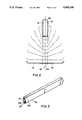
- FIG. 1 is a perspective view of a wide coil of material painted to provide the painted portion of a spacer bar, incorporating the teachings of the present invention
- FIG. 2 is an end view of a slit coil of material shown in a successive folding process to form a rectangular spacer bar, incorporating the teaching of the present invention.
- FIG. 3 is a perspective view of a painted spacer bar, incorporating the teachings of the present invention.
- FIG. 1 there is shown a sheet of material 10 which is made of metal, preferably aluminum.
- the sheet 10 normally is that taken off a coil of material which is processed into spacer bars.
- the sheet width is approximately 24" but may be of any other size convenient to the manufacturing process.
- the sheet 10 is processed by slitting it into narrow coils which are then formed into a rectangular shape to form a spacer bar.
- the width of the coil of course will vary with the size and shape of the spacer being fabricated.
- a typical forming process is illustrated in FIG. 2 with regard to a rectangular shaped spacer.
- the method disclosed herein is equally applicable to spacers of differing sizes and shapes.
- the sheet material Prior to slitting the sheet material is painted in the desired color e.g. white. To effect the painting of a spacer bar along its exposed side, the width of material used to form the spacer bar is painted only along a section thereof.
- portion 22 Prior to slitting however, the portion of the material which would form the exposed portion of spacer bar in the assembled window (i.e. inside and between the panes of glass) is painted with a desired color, typically white. This portion is designated with the numeral 22.
- portion 22 which is painted provides an aesthetically pleasing appearance in the assembled window whereas heretofore exposed metal would normally show.
- painting of the entire sheet material is avoided, just a sufficient width need be applied thus reducing the amount of paint used, the cost of production and leaving the surfaces on which the glass is bonded bare metal, providing for a more desired bonding effect.
- portion 22 On the opposite side of portion 22 the spacer bar joined in a know fashion such as welding along line 24 to complete the spacer bar 20.
Landscapes
- Engineering & Computer Science (AREA)
- Civil Engineering (AREA)
- Structural Engineering (AREA)
- Joining Of Glass To Other Materials (AREA)
Abstract
Description
Claims (4)
Priority Applications (1)
| Application Number | Priority Date | Filing Date | Title |
|---|---|---|---|
| US07/674,673 US5088308A (en) | 1990-12-20 | 1991-03-25 | Method of making spacer bars |
Applications Claiming Priority (2)
| Application Number | Priority Date | Filing Date | Title |
|---|---|---|---|
| US07/630,517 US5088307A (en) | 1990-12-20 | 1990-12-20 | Method of making muntin bars |
| US07/674,673 US5088308A (en) | 1990-12-20 | 1991-03-25 | Method of making spacer bars |
Related Parent Applications (1)
| Application Number | Title | Priority Date | Filing Date |
|---|---|---|---|
| US07/630,517 Continuation-In-Part US5088307A (en) | 1990-12-20 | 1990-12-20 | Method of making muntin bars |
Publications (1)
| Publication Number | Publication Date |
|---|---|
| US5088308A true US5088308A (en) | 1992-02-18 |
Family
ID=27091173
Family Applications (1)
| Application Number | Title | Priority Date | Filing Date |
|---|---|---|---|
| US07/674,673 Expired - Fee Related US5088308A (en) | 1990-12-20 | 1991-03-25 | Method of making spacer bars |
Country Status (1)
| Country | Link |
|---|---|
| US (1) | US5088308A (en) |
Citations (7)
| Publication number | Priority date | Publication date | Assignee | Title |
|---|---|---|---|---|
| US2156107A (en) * | 1935-11-04 | 1939-04-25 | Joseph H Bowman | Painted hoop and method of making it |
| US3438110A (en) * | 1965-02-27 | 1969-04-15 | Federal Weather Strips Inc | Method of making a tube having perforations through the wall thereof |
| US3832962A (en) * | 1971-08-23 | 1974-09-03 | Aluminum Co Of America | Precoating of aluminum can sheet |
| US4455850A (en) * | 1980-12-31 | 1984-06-26 | E. I. Du Pont De Nemours And Company | Can manufacture |
| JPS61115624A (en) * | 1984-11-12 | 1986-06-03 | Toshiba Corp | Working method of colored steel plate |
| SU1326365A1 (en) * | 1986-03-07 | 1987-07-30 | Кировский сельскохозяйственный институт | Method of producing shells |
| US4723388A (en) * | 1985-04-26 | 1988-02-09 | Mansion Industries, Inc. | Easily formable grid for windows and the like |
-
1991
- 1991-03-25 US US07/674,673 patent/US5088308A/en not_active Expired - Fee Related
Patent Citations (7)
| Publication number | Priority date | Publication date | Assignee | Title |
|---|---|---|---|---|
| US2156107A (en) * | 1935-11-04 | 1939-04-25 | Joseph H Bowman | Painted hoop and method of making it |
| US3438110A (en) * | 1965-02-27 | 1969-04-15 | Federal Weather Strips Inc | Method of making a tube having perforations through the wall thereof |
| US3832962A (en) * | 1971-08-23 | 1974-09-03 | Aluminum Co Of America | Precoating of aluminum can sheet |
| US4455850A (en) * | 1980-12-31 | 1984-06-26 | E. I. Du Pont De Nemours And Company | Can manufacture |
| JPS61115624A (en) * | 1984-11-12 | 1986-06-03 | Toshiba Corp | Working method of colored steel plate |
| US4723388A (en) * | 1985-04-26 | 1988-02-09 | Mansion Industries, Inc. | Easily formable grid for windows and the like |
| SU1326365A1 (en) * | 1986-03-07 | 1987-07-30 | Кировский сельскохозяйственный институт | Method of producing shells |
Similar Documents
| Publication | Publication Date | Title |
|---|---|---|
| US5088307A (en) | Method of making muntin bars | |
| CA2579978C (en) | Muntin bar clip and muntin bar assembly | |
| US3748814A (en) | Decorative metal grid system for windows | |
| CA2162796A1 (en) | Extrusion Product with Decorative Enhancement and Process of Making the Same | |
| US8683771B2 (en) | Adjustable frame assembly and method of assembling the adjustable frame assembly | |
| US6640510B2 (en) | Decorative stained glass and method | |
| US4223499A (en) | Decorative stained glass insert unit for windows | |
| US6708384B2 (en) | Notched muntin bars having two finishes | |
| US5165208A (en) | Hollow sash section for insulation glazing or muntin | |
| CA2322820A1 (en) | Intermediate film for laminated glass | |
| US5088308A (en) | Method of making spacer bars | |
| FI97637B (en) | Hollow molding profile for insulating windows and process for its manufacture | |
| US5075141A (en) | Decorative strips for shower partitions | |
| EP0380529B1 (en) | Tray for cables and method of the manufacturing thereof | |
| ES2038879T3 (en) | MODULAR PANEL FOR COATING, IN PARTICULAR OF CEILINGS. | |
| KR100348534B1 (en) | Sandwich Panel | |
| US3290853A (en) | Metal extrusion | |
| DE68915634D1 (en) | Method of manufacturing an exhibition wall panel and panel made by this method. | |
| EA012230B1 (en) | Sash bar suitable for insulating window units | |
| EP0703415B1 (en) | Front panel for panel-type radiator | |
| JP2574167Y2 (en) | Decorative plate glass | |
| DE2314776A1 (en) | Double-glazed glass panels - sealed by a folded metal strip joined by an insert at its ends | |
| KR20250011535A (en) | Method to prebent a framestrain using wrapping sheet | |
| JPS624513B2 (en) | ||
| CN118309352A (en) | Door leaf layering subassembly and door leaf structure |
Legal Events
| Date | Code | Title | Description |
|---|---|---|---|
| AS | Assignment |
Owner name: HYGRADE METAL MOULDING MANUFACTURING CORP., 540 SM Free format text: ASSIGNMENT OF ASSIGNORS INTEREST.;ASSIGNORS:COLE, RICHARD D.;ANGER, HOWARD T.;REEL/FRAME:005649/0908;SIGNING DATES FROM |
|
| AS | Assignment |
Owner name: CHEMICAL BANK, NEW YORK Free format text: SECURITY INTEREST;ASSIGNOR:HYGRADE METAL MOULDING MANUFACTURING CORP., A CORP. OF NY;REEL/FRAME:006251/0626 Effective date: 19920618 |
|
| FPAY | Fee payment |
Year of fee payment: 4 |
|
| AS | Assignment |
Owner name: CHASE MANHATTAN BANK, THE, NEW YORK Free format text: NOTICE OF AMENDMENT OF COLLATERAL ASSIGNMENT OF PATENTS, TRADEMARKS AND LICENSES;ASSIGNOR:HYGRADE METAL MOULDING MANUFACTURING CORP.;REEL/FRAME:009790/0444 Effective date: 19981119 |
|
| REMI | Maintenance fee reminder mailed | ||
| LAPS | Lapse for failure to pay maintenance fees | ||
| FP | Lapsed due to failure to pay maintenance fee |
Effective date: 20000218 |
|
| STCH | Information on status: patent discontinuation |
Free format text: PATENT EXPIRED DUE TO NONPAYMENT OF MAINTENANCE FEES UNDER 37 CFR 1.362 |