US508702A - Valve mechanism for air-brakes - Google Patents
Valve mechanism for air-brakes Download PDFInfo
- Publication number
- US508702A US508702A US508702DA US508702A US 508702 A US508702 A US 508702A US 508702D A US508702D A US 508702DA US 508702 A US508702 A US 508702A
- Authority
- US
- United States
- Prior art keywords
- valve
- air
- train
- pipe
- chamber
- Prior art date
- Legal status (The legal status is an assumption and is not a legal conclusion. Google has not performed a legal analysis and makes no representation as to the accuracy of the status listed.)
- Expired - Lifetime
Links
- 238000004891 communication Methods 0.000 description 7
- 230000006854 communication Effects 0.000 description 7
- 238000010276 construction Methods 0.000 description 3
- 230000005484 gravity Effects 0.000 description 3
- 230000003028 elevating effect Effects 0.000 description 2
- 240000003834 Triticum spelta Species 0.000 description 1
- 238000009825 accumulation Methods 0.000 description 1
- 230000001747 exhibiting effect Effects 0.000 description 1
Images


Classifications
-
- B—PERFORMING OPERATIONS; TRANSPORTING
- B60—VEHICLES IN GENERAL
- B60T—VEHICLE BRAKE CONTROL SYSTEMS OR PARTS THEREOF; BRAKE CONTROL SYSTEMS OR PARTS THEREOF, IN GENERAL; ARRANGEMENT OF BRAKING ELEMENTS ON VEHICLES IN GENERAL; PORTABLE DEVICES FOR PREVENTING UNWANTED MOVEMENT OF VEHICLES; VEHICLE MODIFICATIONS TO FACILITATE COOLING OF BRAKES
- B60T15/00—Construction arrangement, or operation of valves incorporated in power brake systems and not covered by groups B60T11/00 or B60T13/00
- B60T15/02—Application and release valves
- B60T15/36—Other control devices or valves characterised by definite functions
- B60T15/42—Other control devices or valves characterised by definite functions with a quick braking action, i.e. with accelerating valves actuated by brake-pipe pressure variation
Definitions
- My invention relates to auxiliary valvemechanism for air-brakes, whereby upon thereduction of the air-pressure in the train-pipe in the application of the brakes, air from the train-pipe under each car or vehicle of a train, is permitted to escape, preferably into the atmosphere, the object being to render the action of the brake-system in a long train of cars much more rapid and harmonious than has heretofore been possible.
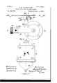
- Figure 1 is a side elevation showing the casingof my improved valve-mechanism and the casing of thetriplevalve-mechanism rigid with the auxiliary airreservoirand brake-cylinder, showing also the train-pipe and the branch pipe that connects the train-pipe with the auxiliary valve-casing.
- Fig. 2 is an opposite side elevation of the easing of the triple-valve mechanism, relative to the elevation shown in Fig. 1, exhibiting the ports that open into the brake-cylinder andv auxiliary-reservoir, respectively.
- Fig. 3 is a bottom plan, showing the head or cap of the,
- Fig. 4 is a side elevation in vertical section on line 44: Figs. 2and 3,1ookingin the direction of the arrow.
- Fig. 5 is a side elevation in vertical section of the triple-valve-mechanism and auxiliary valve-mechanism,.ex-,
- Chambers at and a are connecte'dby bore a endwise of which operates vvalve-stern C that is enlarged at its lower end, as at, 0 such enlargement of the stem nicely fitting within bore a
- a port, M for the passage of air into the auxiliary reservoir (shown in ,dotted lines Fig. 4 and in solid lines Fig. 2) 'opensinto the upper partof chamber a.
- Valve Chas a recess, 0 extending all round the edge of the valve, and vertical orifices 0 between 'saidrecess and the lower face of the valve, said recess and orifices, when the valve is elevated as shown in dotted lines, Fig. 4, admitting air intoport m (shown in dotted lines Fig. 4) that leads from chamber a to and opens into port M.
- the secondary chamber 0/ isconnected by bore a with the exhaustchambera that opens into the external atmosphere.
- a port, N opens into chamber a and leads to the brake-cylinder, B C.
- Casing A, about bore a has a seat, a, for a valve, D, the depending wings or guides D of said valve operating in said bore.
- Valve D has a stem D projecting upwardly through chamber a, and provided with a slot, cl, through which extends lever E that engages the top and bottom walls of said slot.
- Lever E is pivoted at e to casingA and the free end of the lever is adapted to be engaged by valve-stem C during the elevation of valves C and C
- the casing has a lateral screwthreaded opening for assembling the parts and closed by a correspondingly threaded plug F.
- a similar opening on top is closed by plug G provided with a central bore g opening inward for receiving the upper end of the stem of valve D, with a spring g, located as shown, to co-operate with the gravity of the valve and connected lever in closing the valve.
- the operation of the triple-valve mechanism is as follows:
- Meantime valve-stem O has engaged and tilted upward lever E, thereby elevating valve D, (see dotted lines Fig.
- valves 0 and O are still held elevated by reason of the larger lower surface of valve 0 that is exposed, the difference between the areas of the upper and lower surfaces of the valve exposed to the air-pressure within chamber a being the area of the space inclosed within the seat for valve 0 which difference is just sufficient to cause the valves to maintain their elevated positions so long as the airpressure is the same above and below valve 0.
- the elevated positions of the valves may be considered their normal positions, and except while the brakes are being applied the train-pipe and auxiliary reservoir are'consequently always in open relation, thus affording sufficient time for the accumulation of the maximum pressure in the reservoir.
- the pressure is reduced in the trainpipe, and such reduction of pressure below valve 0 causes the latter to descend, thus closing communication between the train-pipe and auxiliary reservoir, then closing the exhaustport, the gravity of valve D and lover E and spring 9 acting in concert to close the exhaust-valve, then opening bore a, whereby the air from the auxiliary reservoir may pass to the brake-cylinder m'a ports M and N, valve C being seated.
- the valves are again lifted to their normal or elevated positions.
- cap or head 13 of the casing of the triplevalve-mechanism is extended laterally and upwardly forming the casing B of my improved auxiliary valveqnechanism.
- casing B Within casing B is a vertical chamber 1) that is closed at the top by a screw-threaded plug 1).
- Chamber 19, at the lower end, is in open relation, by means of a lateral duct b with the lower part of chamber ain the casing of the triplevalve mechanism.
- Chamber 1 at its upper end, is in open relation,by means of a lateral duct,b with branch-pipe, B19, that as already indicated, leads from the train-pipe, casing B terminating in a nozzle 13 at the outer end of duct b for attaching the branch pipe, all the air conducted from the train pipe to the auxiliary reservoir, through parts A, B, entering at said nozzle.
- Endwise of chamber 11 is adapted to operate a piston, O, that fits nicely within the surrounding walls of chamber 12, but is preferably reduced in size, as at O, to reduce the friction and render the same as light as practicable.
- Piston O has an upwardly-extending stem, 0 that is slotted, as at 0 for the reception of the free end of a lever, P, that extends lengthwise of duct 12 and is pivoted at its opposite end, as at P, to casing B.
- a valve, P Integral with lever P is a valve, P, that is adapted to open and close a port I) in casing B. opens preferably into the atmosphere, and casing B, about the inner end of said port, has a seat 1) for valve P
- Piston O is provided with a port, 0 preferably centrally located and comparatively narrow as shown.
- Port O leads-from slot 0 that is in open relation with duct 17 to the lower end of the piston.
- Duct b in the normal position of parts shown in solid lines, is in open relation with chamber a, and in Fig. 4 of the drawings referred to, such communication is shown through chamber b slot 0 port 0 and duct b the sizeof the free end of lever P being such that it does not entirely fill the width of slot 0?.
- valve P permits a quantity of air from the train-pipe or rather, from the branch-pipe that leads from the train-pipe, to escape through port 5
- Valve P remains open but a small fraction of a second, which is sufficient; that is, it requires but a fraction of a second to reestablish the equilibrium in the air-pressure above and below piston O, valve P being closed upon the descent of the piston caused by the action of a spring Q, located as shown, in concert with the gravity of lever P and said piston.
- casing B at the top of duct b has a screw-threaded bore closed by a correspondingly threaded plugB by removing which and plug b, access is had to the interior of the casin g for assembling the valve mechanism.
- valve P remains closed.
- Fig. 5 is shown asomewhat modified construction and arrangement of the members of my improved mechanism; Among the principal changes may be mentioned 'that chamber a of the casing of the triple-valve mechanism is in direct communication with duct 79 but I prefer the construction and arrangement of parts shown in Fig. 4, for the reason that the interposition of. piston 0 with its re-.'
- valve mechanism for air-brakes the combination with the triple-valve-mechanism and inclosing casing having a chamber, a, extending below the triplewaive-mechanism, and a chamber, b, in open relation with chamber a and adapted to communicate with the train-pipe of the air-brakes, of a piston adapted to operate endwise of chamber 1) and havin g a restricted port or passage-way, a port, I)",
- the combination with trainpipe and triple valve-mechanism, of a port for permitting the escape of air from the trainpipe, a valve normally closing said port, suitable means for retaining said valve in its closed position, a chamber located between said valve and triple-valve-mechanism, a piston provided with a restricted port or passageway and adapted to reciprocate endwise of said chamber, the piston being operatively connected with the aforesaid valve in such a manner that its restricted port or passage way shall, in the normal position of parts, be in open relation with the train-pipe, and. the arrangement of parts being such that a sudden reduction of pressure within the trainpipe shall automatically actuate said piston to open the aforesaid valve, substantially as and for the purpose set forth.
- valve-mechanism for air-brakes the combination with the triple-valve-mechanism and casing for said mechanism, said casing being provided with a chamber, a, and a casing, B, rigid with the casing of the triplevalve mechanism and having a chamber, b, in open relation With chambera and adapted to communicate with the train-pipe of the air-brakes, of a port, b adapted to permit the escape of air from the train-pipe, a valve for closing said port, a longitudi[tally-perforated piston adapted to operate endwise of chamber 1) and operativelyconnected with the aforesaid valve, and a spring acting in'the direction to retain the valve aforesaid seated, the arrangement of parts being substantially as shown and for the purpose specified.
Landscapes
- Engineering & Computer Science (AREA)
- Transportation (AREA)
- Mechanical Engineering (AREA)
- Valves And Accessory Devices For Braking Systems (AREA)
Description
(No Model.) v 3 Sheets-Sheet 1.
T. HABERKORN. VALVE MECHANISM FOR AIR BRAKES.
No. 508,702. Patented Nov. 14, 1893.
I11 ?/6 246 or:
ya: mno
(N0 Model.) 3 SheetsSheet 2.
. T. H. HABERKORN. VALVE MECHANISM FOR AIR BRAKES.
No. 508,702. Patented Nov. 14, 1893.
'to make and use the same.
UNITED STATES PATENT OFFIcE THEODORE H. HABERKORN, FORT WAYNE, INDIANA.
VALVE MECHANISM FOR AIR-BRAKES.
SPECIFICATION forming part of Letters Patent No. 508,702, dated November 14, 1893.
Application filed August 16,1892. Serial No. 44:3,196. (No model.)
To all whom it may concern/,
Be it known that I, THEODORE H. HABER KORN, of Fort Wayne, in the county of Allen and State of Indiana, have invented certain new and useful Improvements in Valve Mechanism for Air-Brakes; and I do hereby declare the following to be a full,clear, and .exact description of the invention, such as will enable others skilled in the art to which it pertains My invention relates to auxiliary valvemechanism for air-brakes, whereby upon thereduction of the air-pressure in the train-pipe in the application of the brakes, air from the train-pipe under each car or vehicle of a train, is permitted to escape, preferably into the atmosphere, the object being to render the action of the brake-system in a long train of cars much more rapid and harmonious than has heretofore been possible.
I would here remark that the casing of my improved auxiliary valve-mechanism is pref-V erably integral-with the-head or capof the casing of the triple-valve mechanism and in the accompanying drawings, Figure 1 is a side elevation showing the casingof my improved valve-mechanism and the casing of thetriplevalve-mechanism rigid with the auxiliary airreservoirand brake-cylinder, showing also the train-pipe and the branch pipe that connects the train-pipe with the auxiliary valve-casing. Fig. 2 is an opposite side elevation of the easing of the triple-valve mechanism, relative to the elevation shown in Fig. 1, exhibiting the ports that open into the brake-cylinder andv auxiliary-reservoir, respectively. Fig. 3 is a bottom plan, showing the head or cap of the,
casing of the triple-valve-mechanism and the casing of my improved auxiliary-mechanism. Fig. 4 is a side elevation in vertical section on line 44: Figs. 2and 3,1ookingin the direction of the arrow. Fig. 5 is a side elevation in vertical section of the triple-valve-mechanism and auxiliary valve-mechanism,.ex-,
hibiting a somewhat modified construction and arrangement of parts. 7
Before proceedin g with a description of my present invention, I willbriefly describe what is known as the HaberkOrntriple-valve mechanism for air-brakes and its opera on, as dis- Casing A has three compartments or cham- 'bers, a, a and M, respectively. Within the :larger or primary chamber, a, operate valves 0 and C the surrounding walls of said chamber nicely fitting valve 0, and said chamber is closed below by a cap or head B. The up-I per section of this cap or head .is bored to. receive wings or guides O of valve 0, the
cap having a seat, I), for said valve. Chainber at, below valve 0, is connected with the train-pipe T19, as hereinafter described, that leads along under the cars of atrain and supplies the different auxiliary air-reservoirs wherein compressed air is stored for operating the respective brake-cylinders of the different cars. Chambers at and a are connecte'dby bore a endwise of which operates vvalve-stern C that is enlarged at its lower end, as at, 0 such enlargement of the stem nicely fitting within bore a Enlargement 'O of the valve-stem, at its lower end, terminates in valve, C ,.(al'ready referred to) that 'is integral with valve 0, thetop wall of chamher a about the lower end of bore a having a seat a forvalve 0 A port, M, for the passage of air into the auxiliary reservoir (shown in ,dotted lines Fig. 4 and in solid lines Fig. 2) 'opensinto the upper partof chamber a. Valve Chas a recess, 0 extending all round the edge of the valve, and vertical orifices 0 between 'saidrecess and the lower face of the valve, said recess and orifices, when the valve is elevated as shown in dotted lines, Fig. 4, admitting air intoport m (shown in dotted lines Fig. 4) that leads from chamber a to and opens into port M. The secondary chamber 0/ isconnected by bore a with the exhaustchambera that opens into the external atmosphere. A port, N, opens into chamber a and leads to the brake-cylinder, B C. Casing A, about bore a has a seat, a, for a valve, D, the depending wings or guides D of said valve operating in said bore. Valve D has a stem D projecting upwardly through chamber a, and provided with a slot, cl, through which extends lever E that engages the top and bottom walls of said slot. Lever E is pivoted at e to casingA and the free end of the lever is adapted to be engaged by valve-stem C during the elevation of valves C and C The casing has a lateral screwthreaded opening for assembling the parts and closed by a correspondingly threaded plug F. A similar opening on top is closed by plug G provided with a central bore g opening inward for receiving the upper end of the stem of valve D, with a spring g, located as shown, to co-operate with the gravity of the valve and connected lever in closing the valve.
The operation of the triple-valve mechanism is as follows:The air under pressure, forced along through the train-pipe from the engine, enters chamber a below valve C, elevating valves 0 C to the position shown in dotted lines, Fig. 4, thus seating valve 0 thereby closing bore a --in other words closing communication between the auxiliary air-reservoir and the brake-cylinder. Meantime valve-stem O has engaged and tilted upward lever E, thereby elevating valve D, (see dotted lines Fig. 4) whereby communication is opened from the brake-cylinder to exhaustchamber a and thence to the atmosphere, and in such position of parts the air-supply from the train-pipe passes 'via orifices (J and recess G in valve 0, and ports m and M in the casing to the auxiliary-reservoir, and when the airpressure in the reservoir becomes equal to the pressure in the train-pipe, valves 0 and O are still held elevated by reason of the larger lower surface of valve 0 that is exposed, the difference between the areas of the upper and lower surfaces of the valve exposed to the air-pressure within chamber a being the area of the space inclosed within the seat for valve 0 which difference is just sufficient to cause the valves to maintain their elevated positions so long as the airpressure is the same above and below valve 0. The elevated positions of the valves may be considered their normal positions, and except while the brakes are being applied the train-pipe and auxiliary reservoir are'consequently always in open relation, thus affording sufficient time for the accumulation of the maximum pressure in the reservoir. When it is desired to apply the brakes, the pressure is reduced in the trainpipe, and such reduction of pressure below valve 0 causes the latter to descend, thus closing communication between the train-pipe and auxiliary reservoir, then closing the exhaustport, the gravity of valve D and lover E and spring 9 acting in concert to close the exhaust-valve, then opening bore a, whereby the air from the auxiliary reservoir may pass to the brake-cylinder m'a ports M and N, valve C being seated. When the maximum airpressure is re-established in the train-pipe the valves are again lifted to their normal or elevated positions.
Having thus disclosed the manner of operating the brakes as heretofore through the agency of what is known as the Haberkorn triple-valve mechanism, I will now proceed with a description of my improved auxiliary valve-mechanism.
Referring to the same figures of drawings, (viz:-1, 2, 3 and 4) it will be observed that cap or head 13 of the casing of the triplevalve-mechanism, is extended laterally and upwardly forming the casing B of my improved auxiliary valveqnechanism. Within casing B is a vertical chamber 1) that is closed at the top by a screw-threaded plug 1). Chamber 19, at the lower end, is in open relation, by means of a lateral duct b with the lower part of chamber ain the casing of the triplevalve mechanism. Chamber 1), at its upper end, is in open relation,by means of a lateral duct,b with branch-pipe, B19, that as already indicated, leads from the train-pipe, casing B terminating in a nozzle 13 at the outer end of duct b for attaching the branch pipe, all the air conducted from the train pipe to the auxiliary reservoir, through parts A, B, entering at said nozzle. Endwise of chamber 11 is adapted to operate a piston, O, that fits nicely within the surrounding walls of chamber 12, but is preferably reduced in size, as at O, to reduce the friction and render the same as light as practicable. Piston O has an upwardly-extending stem, 0 that is slotted, as at 0 for the reception of the free end of a lever, P, that extends lengthwise of duct 12 and is pivoted at its opposite end, as at P, to casing B. Integral with lever P is a valve, P, that is adapted to open and close a port I) in casing B. opens preferably into the atmosphere, and casing B, about the inner end of said port, has a seat 1) for valve P Piston O is provided with a port, 0 preferably centrally located and comparatively narrow as shown. Port O leads-from slot 0 that is in open relation with duct 17 to the lower end of the piston. Duct b in the normal position of parts shown in solid lines, is in open relation with chamber a, and in Fig. 4 of the drawings referred to, such communication is shown through chamber b slot 0 port 0 and duct b the sizeof the free end of lever P being such that it does not entirely fill the width of slot 0?. The bottom wall of slot 0 is horizontal, and the lower side of the free end of lever P is flat as at P and, in the closed position of valve, P is parallel with the bottom of slot 0 or approximately so, but does not close the communication between port 0 and duct 5 It will therefore be readily under- Port 12 leads from duct b and stood that when a sudden reduction in the air-pressure of the train-pipeis effected this will be momentarily closed, resulting in apositive opening of valve P, as equilibrium of air-pressure at opposite ends of piston 0 cannot be established until the piston has tilted lever P sufiiciently to reopen comm unication between duct b? and port 0, as shown in dotted lines. This opening of valve P permits a quantity of air from the train-pipe or rather, from the branch-pipe that leads from the train-pipe, to escape through port 5 Valve P remains open but a small fraction of a second, which is sufficient; that is, it requires but a fraction of a second to reestablish the equilibrium in the air-pressure above and below piston O, valve P being closed upon the descent of the piston caused by the action of a spring Q, located as shown, in concert with the gravity of lever P and said piston. Referring to the same figure (4) of the drawings, casing B at the top of duct b, has a screw-threaded bore closed by a correspondingly threaded plugB by removing which and plug b, access is had to the interior of the casin g for assembling the valve mechanism.
I would here remark that the air-pressure in the train-pipe is usually about seventy pounds per square inch and the same pressure exists at opposite ends of piston 0.
By the employment of my improved mechanism, owing to the fact that a quantity of air is discharged from the train-pipe at every car or vehicle, a uniform reduction of airpressure is effected almost simultaneously the entire length of the train-pipe; hence, the triple-valve mechanism of the brakes of the different cars or vehicles act approximately simultaneously, resulting in a mostrapid and harmonious application of the brakes throughout the train. Of course, a difierence in the air-pressure at opposite ends of piston O is only effected upon a sudden reduction of airpressure in the train-pipe. When the brakes are applied gradually by means of a slow reduction of the air-pressure in the train-pipe,
the difference aforesaid in the'airpressure at opposite ends of piston O is not effected and consequently valve P remains closed.
In Fig. 5 is shown asomewhat modified construction and arrangement of the members of my improved mechanism; Among the principal changes may be mentioned 'that chamber a of the casing of the triple-valve mechanism is in direct communication with duct 79 but I prefer the construction and arrangement of parts shown in Fig. 4, for the reason that the interposition of. piston 0 with its re-.'
stricted air-passageway or port 0 renders the action ofthe triple-valve mechanism more gentle in its operation.
What I claim is- 1. In valve mechanism for air-brakes, the combination with the triple-valve-mechanism and inclosing casing having a chamber, a, extending below the triplewaive-mechanism, and a chamber, b, in open relation with chamber a and adapted to communicate with the train-pipe of the air-brakes, of a piston adapted to operate endwise of chamber 1) and havin g a restricted port or passage-way, a port, I)",
and a valve, for closing said port, operatively connected with the aforesaid piston, substantially asand for the purpose set forth.
2. In air-brakes, the combination with trainpipe and triple=valve-mechanism, of a port for permitting the escape of air from the trainpipe, a valve normally closing said port, suitable means for retaining said valve in its closed position, a chamber located between said valve and triple-valve-mechanism, a piston provided with a restricted port or passageway and adapted to reciprocate endwise of said chamber, the piston being operatively connected with the aforesaid valve in such a manner that its restricted port or passage way shall, in the normal position of parts, be in open relation with the train-pipe, and. the arrangement of parts being such that a sudden reduction of pressure within the trainpipe shall automatically actuate said piston to open the aforesaid valve, substantially as and for the purpose set forth.
,3. In valve-mechanism for air-brakes, the combination with the triple-valve-mechanism and casing for said mechanism, said casing being provided with a chamber, a, and a casing, B, rigid with the casing of the triplevalve mechanism and having a chamber, b, in open relation With chambera and adapted to communicate with the train-pipe of the air-brakes, of a port, b adapted to permit the escape of air from the train-pipe, a valve for closing said port, a longitudi[tally-perforated piston adapted to operate endwise of chamber 1) and operativelyconnected with the aforesaid valve, and a spring acting in'the direction to retain the valve aforesaid seated, the arrangement of parts being substantially as shown and for the purpose specified.
4. In air-brakes, the combination with the train-pipe and triple-valve-mechanism' opera-' tively connected With said pipe, of a port, W, for permitting the escape of air from the train-pipe, a valve, P for closingsaid port, a vertical chamber, b, located between said- Valve and triple-valve-mechanism, a longitudinally perforated piston, substantially as shown, operatively connected with said valve and adapted to operate endwise of chamber b, and suitable means for holding said valve to its seat, the arrangement of parts being tion, in the presence of two witnesses, this such that a sudden reduction of air-press' 13th day of July, 1892. we within the train pipe will automatically 1 V actuate said piston to open the aforesaid THEODORE HABERKORN' 5 valve, substantially as and for the purpose Witnesses:
set forth. BESSIE RACINE,
In testimony whereof I sign this specifica- PAUL F. KUHNE.
Publications (1)
| Publication Number | Publication Date |
|---|---|
| US508702A true US508702A (en) | 1893-11-14 |
Family
ID=2577531
Family Applications (1)
| Application Number | Title | Priority Date | Filing Date |
|---|---|---|---|
| US508702D Expired - Lifetime US508702A (en) | Valve mechanism for air-brakes |
Country Status (1)
| Country | Link |
|---|---|
| US (1) | US508702A (en) |
-
0
- US US508702D patent/US508702A/en not_active Expired - Lifetime
Similar Documents
| Publication | Publication Date | Title |
|---|---|---|
| US508702A (en) | Valve mechanism for air-brakes | |
| US762680A (en) | Valve mechanism. | |
| US594464A (en) | Air brake | |
| US707474A (en) | Fluid-pressure brake. | |
| US591262A (en) | Pneumatic and electric controlled brake | |
| US707473A (en) | Fluid-pressure brake | |
| US562773A (en) | Fluid-pressure brake | |
| US574866A (en) | -hog-an | |
| US801775A (en) | Triple valve. | |
| US697694A (en) | Pressure-retaining valve for air-brakes. | |
| US610947A (en) | Air-brake | |
| US621779A (en) | Signors of one-fourth to charles g | |
| US416516A (en) | Automatic pressure-retaining valve for air-brakes | |
| US749263A (en) | Automatic fluid pressure brake mechanism | |
| US610948A (en) | Air-brake | |
| US608030A (en) | Murray corrington | |
| US547484A (en) | Fluid-pressure automatic brake mechanism | |
| US580843A (en) | Fluid-pressure brake system | |
| US571115A (en) | Sylvania | |
| US650017A (en) | Quick-action triple valve. | |
| US1776290A (en) | Fluid-pressure brake | |
| US448827A (en) | westing-house | |
| US701328A (en) | Continuous automatic air-brake system. | |
| US702926A (en) | Automatic fluid-pressure brake apparatus. | |
| US757016A (en) | Triple valve for air-brake systems. |