US5084120A - Removable or hinged component for covering openings in the fuselage of an aircraft - Google Patents
Removable or hinged component for covering openings in the fuselage of an aircraft Download PDFInfo
- Publication number
- US5084120A US5084120A US07/445,038 US44503889A US5084120A US 5084120 A US5084120 A US 5084120A US 44503889 A US44503889 A US 44503889A US 5084120 A US5084120 A US 5084120A
- Authority
- US
- United States
- Prior art keywords
- profiles
- base layer
- process according
- vacuum foil
- supporting surface
- Prior art date
- Legal status (The legal status is an assumption and is not a legal conclusion. Google has not performed a legal analysis and makes no representation as to the accuracy of the status listed.)
- Expired - Fee Related
Links
- 239000011888 foil Substances 0.000 claims abstract description 31
- 238000004519 manufacturing process Methods 0.000 claims abstract description 8
- 238000000034 method Methods 0.000 claims description 13
- 229920001971 elastomer Polymers 0.000 claims description 9
- 210000002445 nipple Anatomy 0.000 claims description 7
- 239000004033 plastic Substances 0.000 claims description 3
- 229920003023 plastic Polymers 0.000 claims description 3
- 238000005253 cladding Methods 0.000 abstract description 9
- 229920003002 synthetic resin Polymers 0.000 abstract description 9
- 239000000057 synthetic resin Substances 0.000 abstract description 9
- 239000000835 fiber Substances 0.000 abstract description 8
- OKTJSMMVPCPJKN-UHFFFAOYSA-N Carbon Chemical compound [C] OKTJSMMVPCPJKN-UHFFFAOYSA-N 0.000 abstract description 3
- 229910052799 carbon Inorganic materials 0.000 abstract description 3
- 230000007797 corrosion Effects 0.000 abstract 1
- 238000005260 corrosion Methods 0.000 abstract 1
- 210000003414 extremity Anatomy 0.000 description 14
- XAGFODPZIPBFFR-UHFFFAOYSA-N aluminium Chemical compound [Al] XAGFODPZIPBFFR-UHFFFAOYSA-N 0.000 description 3
- 229910052782 aluminium Inorganic materials 0.000 description 3
- 239000004411 aluminium Substances 0.000 description 3
- 239000003795 chemical substances by application Substances 0.000 description 3
- 230000007704 transition Effects 0.000 description 3
- KXGFMDJXCMQABM-UHFFFAOYSA-N 2-methoxy-6-methylphenol Chemical compound [CH]OC1=CC=CC([CH])=C1O KXGFMDJXCMQABM-UHFFFAOYSA-N 0.000 description 1
- 238000004378 air conditioning Methods 0.000 description 1
- 238000003486 chemical etching Methods 0.000 description 1
- 239000002131 composite material Substances 0.000 description 1
- 239000003822 epoxy resin Substances 0.000 description 1
- 239000005007 epoxy-phenolic resin Substances 0.000 description 1
- 238000011067 equilibration Methods 0.000 description 1
- 238000004880 explosion Methods 0.000 description 1
- 238000012423 maintenance Methods 0.000 description 1
- 230000007257 malfunction Effects 0.000 description 1
- 229920001568 phenolic resin Polymers 0.000 description 1
- 229920006122 polyamide resin Polymers 0.000 description 1
- 229920000647 polyepoxide Polymers 0.000 description 1
- 230000002787 reinforcement Effects 0.000 description 1
- 210000001364 upper extremity Anatomy 0.000 description 1
Images

Classifications
-
- B—PERFORMING OPERATIONS; TRANSPORTING
- B64—AIRCRAFT; AVIATION; COSMONAUTICS
- B64C—AEROPLANES; HELICOPTERS
- B64C1/00—Fuselages; Constructional features common to fuselages, wings, stabilising surfaces or the like
- B64C1/14—Windows; Doors; Hatch covers or access panels; Surrounding frame structures; Canopies; Windscreens accessories therefor, e.g. pressure sensors, water deflectors, hinges, seals, handles, latches, windscreen wipers
- B64C1/1407—Doors; surrounding frames
- B64C1/1461—Structures of doors or surrounding frames
-
- Y—GENERAL TAGGING OF NEW TECHNOLOGICAL DEVELOPMENTS; GENERAL TAGGING OF CROSS-SECTIONAL TECHNOLOGIES SPANNING OVER SEVERAL SECTIONS OF THE IPC; TECHNICAL SUBJECTS COVERED BY FORMER USPC CROSS-REFERENCE ART COLLECTIONS [XRACs] AND DIGESTS
- Y02—TECHNOLOGIES OR APPLICATIONS FOR MITIGATION OR ADAPTATION AGAINST CLIMATE CHANGE
- Y02T—CLIMATE CHANGE MITIGATION TECHNOLOGIES RELATED TO TRANSPORTATION
- Y02T50/00—Aeronautics or air transport
- Y02T50/40—Weight reduction
-
- Y—GENERAL TAGGING OF NEW TECHNOLOGICAL DEVELOPMENTS; GENERAL TAGGING OF CROSS-SECTIONAL TECHNOLOGIES SPANNING OVER SEVERAL SECTIONS OF THE IPC; TECHNICAL SUBJECTS COVERED BY FORMER USPC CROSS-REFERENCE ART COLLECTIONS [XRACs] AND DIGESTS
- Y10—TECHNICAL SUBJECTS COVERED BY FORMER USPC
- Y10S—TECHNICAL SUBJECTS COVERED BY FORMER USPC CROSS-REFERENCE ART COLLECTIONS [XRACs] AND DIGESTS
- Y10S29/00—Metal working
- Y10S29/044—Vacuum
-
- Y—GENERAL TAGGING OF NEW TECHNOLOGICAL DEVELOPMENTS; GENERAL TAGGING OF CROSS-SECTIONAL TECHNOLOGIES SPANNING OVER SEVERAL SECTIONS OF THE IPC; TECHNICAL SUBJECTS COVERED BY FORMER USPC CROSS-REFERENCE ART COLLECTIONS [XRACs] AND DIGESTS
- Y10—TECHNICAL SUBJECTS COVERED BY FORMER USPC
- Y10T—TECHNICAL SUBJECTS COVERED BY FORMER US CLASSIFICATION
- Y10T29/00—Metal working
- Y10T29/30—Foil or other thin sheet-metal making or treating
- Y10T29/301—Method
- Y10T29/302—Clad or other composite foil or thin metal making
-
- Y—GENERAL TAGGING OF NEW TECHNOLOGICAL DEVELOPMENTS; GENERAL TAGGING OF CROSS-SECTIONAL TECHNOLOGIES SPANNING OVER SEVERAL SECTIONS OF THE IPC; TECHNICAL SUBJECTS COVERED BY FORMER USPC CROSS-REFERENCE ART COLLECTIONS [XRACs] AND DIGESTS
- Y10—TECHNICAL SUBJECTS COVERED BY FORMER USPC
- Y10T—TECHNICAL SUBJECTS COVERED BY FORMER US CLASSIFICATION
- Y10T428/00—Stock material or miscellaneous articles
- Y10T428/23—Sheet including cover or casing
- Y10T428/239—Complete cover or casing
-
- Y—GENERAL TAGGING OF NEW TECHNOLOGICAL DEVELOPMENTS; GENERAL TAGGING OF CROSS-SECTIONAL TECHNOLOGIES SPANNING OVER SEVERAL SECTIONS OF THE IPC; TECHNICAL SUBJECTS COVERED BY FORMER USPC CROSS-REFERENCE ART COLLECTIONS [XRACs] AND DIGESTS
- Y10—TECHNICAL SUBJECTS COVERED BY FORMER USPC
- Y10T—TECHNICAL SUBJECTS COVERED BY FORMER US CLASSIFICATION
- Y10T428/00—Stock material or miscellaneous articles
- Y10T428/24—Structurally defined web or sheet [e.g., overall dimension, etc.]
- Y10T428/24174—Structurally defined web or sheet [e.g., overall dimension, etc.] including sheet or component perpendicular to plane of web or sheet
- Y10T428/24182—Inward from edge of web or sheet
-
- Y—GENERAL TAGGING OF NEW TECHNOLOGICAL DEVELOPMENTS; GENERAL TAGGING OF CROSS-SECTIONAL TECHNOLOGIES SPANNING OVER SEVERAL SECTIONS OF THE IPC; TECHNICAL SUBJECTS COVERED BY FORMER USPC CROSS-REFERENCE ART COLLECTIONS [XRACs] AND DIGESTS
- Y10—TECHNICAL SUBJECTS COVERED BY FORMER USPC
- Y10T—TECHNICAL SUBJECTS COVERED BY FORMER US CLASSIFICATION
- Y10T428/00—Stock material or miscellaneous articles
- Y10T428/24—Structurally defined web or sheet [e.g., overall dimension, etc.]
- Y10T428/24479—Structurally defined web or sheet [e.g., overall dimension, etc.] including variation in thickness
- Y10T428/24521—Structurally defined web or sheet [e.g., overall dimension, etc.] including variation in thickness with component conforming to contour of nonplanar surface
- Y10T428/24545—Containing metal or metal compound
-
- Y—GENERAL TAGGING OF NEW TECHNOLOGICAL DEVELOPMENTS; GENERAL TAGGING OF CROSS-SECTIONAL TECHNOLOGIES SPANNING OVER SEVERAL SECTIONS OF THE IPC; TECHNICAL SUBJECTS COVERED BY FORMER USPC CROSS-REFERENCE ART COLLECTIONS [XRACs] AND DIGESTS
- Y10—TECHNICAL SUBJECTS COVERED BY FORMER USPC
- Y10T—TECHNICAL SUBJECTS COVERED BY FORMER US CLASSIFICATION
- Y10T428/00—Stock material or miscellaneous articles
- Y10T428/24—Structurally defined web or sheet [e.g., overall dimension, etc.]
- Y10T428/24628—Nonplanar uniform thickness material
- Y10T428/24661—Forming, or cooperating to form cells
-
- Y—GENERAL TAGGING OF NEW TECHNOLOGICAL DEVELOPMENTS; GENERAL TAGGING OF CROSS-SECTIONAL TECHNOLOGIES SPANNING OVER SEVERAL SECTIONS OF THE IPC; TECHNICAL SUBJECTS COVERED BY FORMER USPC CROSS-REFERENCE ART COLLECTIONS [XRACs] AND DIGESTS
- Y10—TECHNICAL SUBJECTS COVERED BY FORMER USPC
- Y10T—TECHNICAL SUBJECTS COVERED BY FORMER US CLASSIFICATION
- Y10T428/00—Stock material or miscellaneous articles
- Y10T428/24—Structurally defined web or sheet [e.g., overall dimension, etc.]
- Y10T428/24744—Longitudinal or transverse tubular cavity or cell
-
- Y—GENERAL TAGGING OF NEW TECHNOLOGICAL DEVELOPMENTS; GENERAL TAGGING OF CROSS-SECTIONAL TECHNOLOGIES SPANNING OVER SEVERAL SECTIONS OF THE IPC; TECHNICAL SUBJECTS COVERED BY FORMER USPC CROSS-REFERENCE ART COLLECTIONS [XRACs] AND DIGESTS
- Y10—TECHNICAL SUBJECTS COVERED BY FORMER USPC
- Y10T—TECHNICAL SUBJECTS COVERED BY FORMER US CLASSIFICATION
- Y10T428/00—Stock material or miscellaneous articles
- Y10T428/24—Structurally defined web or sheet [e.g., overall dimension, etc.]
- Y10T428/24777—Edge feature
Definitions
- the invention relates to a removable or hinged component for covering apertures in the fuselage of an aircraft, e.g. covering or service ports for aggregates such as an auxiliary gas turbine or air-conditioning plant.
- the covering In the case of failures and servicing of the aggregates, the covering must be capable of rapid removal. This involves usually self-supporting shells of large surface area which are fitted to the fuselage at only a few localities (e.g. hinges) and which are locked to one another or to the fuselage by fast-acting fasteners.
- aluminium having a wall thickness of a few millimeters serving as outer layer and numerous reinforcement ribs for accommodating the closure forces, forces arising from the aerodynamic resistance of the cladding and of pressures resulting from malfunction of the installed aggregates (fire, explosion).
- composite materials comprising a light core and fibrous webs have also been employed.
- the aluminium skin is of reduced wall thickness in localities of reduced load.
- chemical etching is employed or one sheet is adhesively bonded onto a further sheet having cut-away regions.
- a component as set out in the opening paragraph comprises a base layer on which, spaced apart, a plurality of preferably mutually parallel U-profiles is provided, the base portions of which extend transversely to the base layer and one limb of which is flush with the base layer and that at the transition between the base layer and the base portion which faces away from the limb an L-profile is provided in each case, the base layer, U-profile and the L-profile being composed of fibre reinforced, e.g. carbon fibre reinforced fully cured synthetic resin.
- the limbs of at least some successive U-profiles are directed to face the limbs of an end profile.
- the limbs of adjoining U-profiles face each other.
- a cover layer is applied onto the free-standing limbs of the U-profiles, composed of fibre reinforced, e.g. carbon fibre reinforced fully cured synthetic resin.
- the first process for manufacturing the component according to the first embodiment, according to the invention provides that the base layer is applied onto a large area supporting surface having a configuration which in the longitudinal and transverse directions corresponds to the desired configuration of cladding for the aperture, that the U-profiles are applied unto the supporting surface, that thereafter the L-profiles are applied onto that side of the base portion of the inner U-profiles which faces away from the limbs, that onto the U-profiles a grid framed by a frame is applied which holds the U-profile and the L-profiles together, that in a manner known per se a vacuum foil is applied over the structure formed in that manner and is adhesively bonded along the edges of the base layer to the large area supporting surface, whereupon the space between the vacuum foil and the large area supporting surface is evacuated and complete curing takes place at elevated temperature and pressure, whereafter the vacuum foil and the grid are removed.
- the second process for the manufacture of the component according to the second embodiment, in accordance with the invention provides that the base layer is applied onto a large area supporting surface, the configuration of which corresponds in the longitudinal and transverse directions to the desired configuration of the cladding for the aperture, that onto a subsequently removable core of rectangular cross section on both sides of the narrow sides of the core the U-profiles are applied and the unit formed by the the U-profiles including the core is laid onto the base layer, the core being matched to the configuration of the large area supporting surface in the longitudinal direction, that subsequently the L-profiles are fitted on both sides of the U-profiles, that a vacuum foil is applied over the structure formed in the aforesaid manner and is adhesively bonded along the edges of the base layer to the large area supporting surface, whereafter the space between the vacuum foil and the large area supporting surface is evacuated and complete curing takes place at elevated temperature and pressure followed by the removal of the vacuum foil and the core.
- the third process for the manufacture of the component according to the first or second embodiment in accordance with the invention provides that, after the production of the component according to the first or second embodiment a closed rubber bag having an inlet nipple is inserted into each of the spaces between the U-profiles, that a covering layer of fibre-reinforced curable plastics is applied onto the free-standing limbs of the U-profiles and a vacuum foil in the form of a bag is drawn over the entire assembly, the inlet nipples projecting from the vacuum foil and being adhesively bonded thereto in an airtight manner in the region of contact, whereafter the space between the vacuum foil and the rubber bags is evacuated, and a complete curing of the covering layer takes place at elevated temperature and pressure followed by the removal of the vacuum foil and the rubber bags.
- Epoxy resin, phenolic resin or polyamide resin can be used as the plastics.
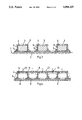
- FIG. 1 a first embodiment of the invention in cross section
- FIG. 2 a diagrammatic view of a grid surrounded by a frame serving for the manufacture
- FIG. 3 a second embodiment of the invention in cross section
- FIG. 4 a third embodiment of the invention in cross section.
- 1 denotes a large area supporting surface, the configuration of which in the longitudinal and transverse direction is adapted to the desired configuration of the cladding.
- the supporting surface 1 extends rectilinearly in the transverse direction, whilst in the longitudinal direction it may for example be of circularly arcuate configuration.
- a base layer 2 of fibre reinforced curable synthetic resin is applied onto this supporting surface.
- the supporting surface 1 is coated with a suitable agent to avoid adherence of the base layer 2.
- Onto the base layer 2, in spaced apart relationship a plurality of U-profiles 4 are placed, the limbs 6a of which are directed to face the limbs 6A' of a terminal profile 4'.
- a grid 14 which as illustrated in FIG. 2 is composed of a frame 15 with handles 16 and angular bridges 19 held between the longitudinal sides 17, 18, the transverse side 20, 21 being connected to struts 22, 23, is placed onto each of the U- and L-profiles 4, 4', 5, 5'.
- a grid 14 which as illustrated in FIG. 2 is composed of a frame 15 with handles 16 and angular bridges 19 held between the longitudinal sides 17, 18, the transverse side 20, 21 being connected to struts 22, 23, is placed onto each of the U- and L-profiles 4, 4', 5, 5'.
- the grid rests with its struts 22, 23 and the horizontal limbs 24 of the bridge members 19 on the upper limbs 6A, 6A' of the U-profiles 6, 6' and by means of the transverse struts 20, 21 as well as the vertical limbs 25 of the bridge members 19, it engages behind the L-profiles 5, 5' whereby the profiles 4, 5, 4', 5' are held in a fixed position on the base layer 2.
- a vacuum foil 7 is placed over the structure formed in that manner and is adhesively bonded along the edges of the base layer 2 onto the supporting surface 1. The space between the vacuum foil 7, the supporting surface 1, the grid 14, the base layer 2 and the profiles 4, 5, 4', 5' is then evacuated.
- 1 denotes a large surface supporting surface, as in FIG. 1, the configuration of which in the longitudinal and transverse directions is adapted to the desired configuration of the cladding.
- the supporting surface 1 is rectilinear in transverse direction whilst in the longitudinal direction it may for example be of circular arcuate shape.
- a base layer 2 of fibre reinforced curable synthetic resin is applied onto this supporting surface.
- the supporting surface 1 is coated with a suitable agent to avoid adhesion of the base layer 2.
- a U-profile 4 of fibre-reinforced curable synthetic resin is placed over a core 3 of rectangular cross section over both narrow sides.
- the core 3 is composed for example of aluminium and is similarly coated with a suitable agent to avoid adhesion of the profile 4 and to render the core 3 removable after this.
- the configuration of the core 3 is adapted to the configuration of the supporting surface 1 in the longitudinal direction (normal to the plane of the drawing) of the latter.
- a plurality of the units thus formed comprising the core 3 as well as two U-profiles 4 is placed in spaced apart relationship onto the base layer 2.
- one L-profile 5 each of fibre-reinforced curable reinforced synthetic resin is fitted along the transition between the base layer 2 and the base portion 6 of the U-profile 4.
- a vacuum foil 7 is applied over the structure thus formed and is adhesively bonded along the edges of the base layer 2 onto the supporting surface 1. The space between the vacuum foil 7 and the supporting surface 1 is subsequently evacuated.
- the fully cured complete component according to FIG. 3 may be provided with a covering 8 of fibre-reinforced curable synthetic resin.
- a rubber bag 9 each having an inlet nipple 10 is inserted into each cavity between the U-profiles 4, to project beyond the end of the component.
- the covering 8 is applied onto the exposed limbs 11 of the U-profile 4.
- a vacuum foil 12 in the form of a bag is now drawn over the entire assembly such that the inlet nipples 10 project from the vacuum foil 12 and are adhesively sealed in an airtight manner in their regions of passage 13.
Landscapes
- Engineering & Computer Science (AREA)
- Mechanical Engineering (AREA)
- Aviation & Aerospace Engineering (AREA)
- Moulding By Coating Moulds (AREA)
- Casting Or Compression Moulding Of Plastics Or The Like (AREA)
- Laminated Bodies (AREA)
- Blow-Moulding Or Thermoforming Of Plastics Or The Like (AREA)
Abstract
Description
Claims (10)
Applications Claiming Priority (4)
| Application Number | Priority Date | Filing Date | Title |
|---|---|---|---|
| AT56187A ATA56187A (en) | 1987-03-10 | 1987-03-10 | DETACHABLE OR SWIVELABLE COMPONENT FOR COVERING OPENINGS IN THE FUSELAGE OF A PLANE |
| AT561/87 | 1987-03-10 | ||
| AT0039888A AT390771B (en) | 1988-02-19 | 1988-02-19 | Component which can be removed or pivoted, for lining (cladding) openings in the fuselage of an aircraft |
| AT398/88 | 1988-02-19 |
Related Parent Applications (1)
| Application Number | Title | Priority Date | Filing Date |
|---|---|---|---|
| US07/166,269 Division US4908254A (en) | 1987-03-10 | 1988-03-10 | Removable or hinged component for covering openings in the fuselage of an aircraft |
Publications (1)
| Publication Number | Publication Date |
|---|---|
| US5084120A true US5084120A (en) | 1992-01-28 |
Family
ID=25592585
Family Applications (2)
| Application Number | Title | Priority Date | Filing Date |
|---|---|---|---|
| US07/166,269 Expired - Fee Related US4908254A (en) | 1987-03-10 | 1988-03-10 | Removable or hinged component for covering openings in the fuselage of an aircraft |
| US07/445,038 Expired - Fee Related US5084120A (en) | 1987-03-10 | 1989-12-04 | Removable or hinged component for covering openings in the fuselage of an aircraft |
Family Applications Before (1)
| Application Number | Title | Priority Date | Filing Date |
|---|---|---|---|
| US07/166,269 Expired - Fee Related US4908254A (en) | 1987-03-10 | 1988-03-10 | Removable or hinged component for covering openings in the fuselage of an aircraft |
Country Status (5)
| Country | Link |
|---|---|
| US (2) | US4908254A (en) |
| JP (1) | JP2683551B2 (en) |
| DE (2) | DE3806594C2 (en) |
| FR (1) | FR2612282B3 (en) |
| GB (1) | GB2203713A (en) |
Cited By (11)
| Publication number | Priority date | Publication date | Assignee | Title |
|---|---|---|---|---|
| US5454895A (en) * | 1992-08-03 | 1995-10-03 | Finmeccanica S.P.A. - Ramo Aziendale Alenia | Process for manufacturing fiber reinforced structures suitable for aeronautic applications |
| WO1996040551A1 (en) * | 1995-06-07 | 1996-12-19 | The Boeing Company | Hybrid metal webbed composite beam |
| US5829716A (en) * | 1995-06-07 | 1998-11-03 | The Boeing Company | Welded aerospace structure using a hybrid metal webbed composite beam |
| US6391246B2 (en) * | 1996-11-15 | 2002-05-21 | Honda Giken Kogyo Kabushiki Kaisha | Method for forming fiber-reinforced composite member |
| US6568637B2 (en) | 2000-07-20 | 2003-05-27 | Eurocopter Deutschland Gmbh | Aircraft door |
| US20050116102A1 (en) * | 2003-11-24 | 2005-06-02 | Airbus France | Aircraft partition designed to separate a cargo part from a cockpit or from a passenger compartment |
| US20070251947A1 (en) * | 2004-05-11 | 2007-11-01 | Mt Aerospace Ag | Container for Receiving or Holding, Respectively, and Storing Liquids as Well as Viscous Substances, and Method for the Production Thereof |
| US20070277470A1 (en) * | 2006-06-06 | 2007-12-06 | Alexei Vichniakov | Lightweight structural panel |
| US20090166473A1 (en) * | 2007-12-27 | 2009-07-02 | Airbus Espana, S.L. | Optimized aircraft manhole |
| US20130154154A1 (en) * | 2011-06-27 | 2013-06-20 | William L. Rodman | Composite structures having cored members |
| US20140311939A1 (en) * | 2010-07-01 | 2014-10-23 | Faurecia Systemes D'echappement | Method For Manufacturing An Ammonia Storage Cartridge, In Particular For A Motor Vehicle Exhaust System |
Families Citing this family (18)
| Publication number | Priority date | Publication date | Assignee | Title |
|---|---|---|---|---|
| US5242523A (en) * | 1992-05-14 | 1993-09-07 | The Boeing Company | Caul and method for bonding and curing intricate composite structures |
| US5622733A (en) * | 1994-10-04 | 1997-04-22 | Rockwell International Corporation | Tooling for the fabrication of composite hollow crown-stiffened skins and panels |
| DE19528664C2 (en) * | 1995-08-04 | 1997-07-31 | Joachim Heyse | Support body made of a composite material |
| US6023806A (en) * | 1996-09-30 | 2000-02-15 | Martin Marietta Materials, Inc. | Modular polymer matrix composite support structure and methods of constructing same |
| US6081955A (en) * | 1996-09-30 | 2000-07-04 | Martin Marietta Materials, Inc. | Modular polymer matrix composite support structure and methods of constructing same |
| US5794402A (en) * | 1996-09-30 | 1998-08-18 | Martin Marietta Materials, Inc. | Modular polymer matrix composite support structure and methods of constructing same |
| DE19832441C1 (en) * | 1998-07-18 | 2000-01-05 | Daimler Chrysler Aerospace | Stringer-reinforced shell production with double curvature using fibrous composite materials, without risk of warping |
| DE10035334B4 (en) | 2000-07-20 | 2007-11-29 | Eurocopter Deutschland Gmbh | Airplane door and an outer skin of an aircraft door |
| US20060222837A1 (en) * | 2005-03-31 | 2006-10-05 | The Boeing Company | Multi-axial laminate composite structures and methods of forming the same |
| US8720825B2 (en) * | 2005-03-31 | 2014-05-13 | The Boeing Company | Composite stiffeners for aerospace vehicles |
| US20060237588A1 (en) * | 2005-03-31 | 2006-10-26 | The Boeing Company | Composite structural member having an undulating web and method for forming the same |
| US7721495B2 (en) * | 2005-03-31 | 2010-05-25 | The Boeing Company | Composite structural members and methods for forming the same |
| US7740932B2 (en) * | 2005-03-31 | 2010-06-22 | The Boeing Company | Hybrid fiberglass composite structures and methods of forming the same |
| US8444087B2 (en) * | 2005-04-28 | 2013-05-21 | The Boeing Company | Composite skin and stringer structure and method for forming the same |
| DE102005038857B4 (en) * | 2005-08-17 | 2010-03-18 | Airbus Deutschland Gmbh | Double-skinned center box |
| DE102006044093B4 (en) * | 2006-09-20 | 2009-01-22 | Airbus Deutschland Gmbh | Disk replacement to fill a window frame |
| US9878773B2 (en) | 2012-12-03 | 2018-01-30 | The Boeing Company | Split resistant composite laminate |
| EP4491505B1 (en) * | 2023-07-11 | 2026-04-22 | Airbus Operations GmbH | Composite aircraft door and method for manufacturing the same |
Citations (10)
| Publication number | Priority date | Publication date | Assignee | Title |
|---|---|---|---|---|
| DE835061C (en) * | 1948-12-18 | 1952-03-27 | Dr Ernst Schnabel | Process and arrangement for pressing molded parts made of plastics |
| DE1704670A1 (en) * | 1968-03-01 | 1971-02-18 | Claudius Fietzek | Plastic laminate with reinforcing ribs and method for making this laminate |
| DE2418110A1 (en) * | 1973-05-11 | 1974-11-28 | Teleflex Inc | BOWDEN TRAIN |
| DE2424068A1 (en) * | 1973-05-18 | 1974-12-05 | Dassault Avions | PROCESS FOR MANUFACTURING COMPONENTS, IN PARTICULAR LAYERS OF HIGH MECHANICAL STRENGTH, IN PARTICULAR FOR AVIATION |
| DE2334132A1 (en) * | 1973-07-05 | 1975-01-23 | Dornier Gmbh | PROFILE STRIP IN FIBER COMPOSITE CONSTRUCTION |
| US3995080A (en) * | 1974-10-07 | 1976-11-30 | General Dynamics Corporation | Filament reinforced structural shapes |
| DE2642523A1 (en) * | 1976-09-22 | 1978-03-23 | Burkhart Dipl Ing Grob | Monocoque construction for aircraft parts - uses two moulds for fibre reinforced plastics to provide reinforcing ribs |
| DE3003552A1 (en) * | 1980-01-31 | 1981-08-06 | Messerschmitt-Bölkow-Blohm GmbH, 8000 München | AREA COMPONENT, ESPECIALLY FOR AIRCRAFT |
| US4299871A (en) * | 1979-09-04 | 1981-11-10 | Grumman Aerospace Corporation | Stitch bond fastening of composite structures |
| DE3614618A1 (en) * | 1986-04-30 | 1987-11-05 | Messerschmitt Boelkow Blohm | SHELL STRUCTURE MADE OF FIBER REINFORCED PLASTIC |
Family Cites Families (5)
| Publication number | Priority date | Publication date | Assignee | Title |
|---|---|---|---|---|
| GB1120381A (en) * | 1964-07-07 | 1968-07-17 | Handley Page Ltd | Improvements in or relating to the manufacture of aerodynamic structures |
| US4556591A (en) * | 1981-09-25 | 1985-12-03 | The Boeing Company | Conductive bonded/bolted joint seals for composite aircraft |
| AU586418B2 (en) * | 1984-02-28 | 1989-07-13 | Offshore Marine Pty. Ltd. | Airfoil construction |
| DE3418110C2 (en) * | 1984-05-16 | 1986-04-03 | Dornier Gmbh, 7990 Friedrichshafen | Process for the production of stiffened, load-bearing structures from fiber-reinforced hardenable plastic |
| US4786343A (en) * | 1985-05-10 | 1988-11-22 | The Boeing Company | Method of making delamination resistant composites |
-
1988
- 1988-02-25 GB GB08804370A patent/GB2203713A/en not_active Withdrawn
- 1988-03-02 FR FR888802619A patent/FR2612282B3/en not_active Expired
- 1988-03-02 DE DE3806594A patent/DE3806594C2/en not_active Expired - Fee Related
- 1988-03-02 DE DE8802737U patent/DE8802737U1/en not_active Expired
- 1988-03-10 US US07/166,269 patent/US4908254A/en not_active Expired - Fee Related
- 1988-03-10 JP JP63057334A patent/JP2683551B2/en not_active Expired - Lifetime
-
1989
- 1989-12-04 US US07/445,038 patent/US5084120A/en not_active Expired - Fee Related
Patent Citations (10)
| Publication number | Priority date | Publication date | Assignee | Title |
|---|---|---|---|---|
| DE835061C (en) * | 1948-12-18 | 1952-03-27 | Dr Ernst Schnabel | Process and arrangement for pressing molded parts made of plastics |
| DE1704670A1 (en) * | 1968-03-01 | 1971-02-18 | Claudius Fietzek | Plastic laminate with reinforcing ribs and method for making this laminate |
| DE2418110A1 (en) * | 1973-05-11 | 1974-11-28 | Teleflex Inc | BOWDEN TRAIN |
| DE2424068A1 (en) * | 1973-05-18 | 1974-12-05 | Dassault Avions | PROCESS FOR MANUFACTURING COMPONENTS, IN PARTICULAR LAYERS OF HIGH MECHANICAL STRENGTH, IN PARTICULAR FOR AVIATION |
| DE2334132A1 (en) * | 1973-07-05 | 1975-01-23 | Dornier Gmbh | PROFILE STRIP IN FIBER COMPOSITE CONSTRUCTION |
| US3995080A (en) * | 1974-10-07 | 1976-11-30 | General Dynamics Corporation | Filament reinforced structural shapes |
| DE2642523A1 (en) * | 1976-09-22 | 1978-03-23 | Burkhart Dipl Ing Grob | Monocoque construction for aircraft parts - uses two moulds for fibre reinforced plastics to provide reinforcing ribs |
| US4299871A (en) * | 1979-09-04 | 1981-11-10 | Grumman Aerospace Corporation | Stitch bond fastening of composite structures |
| DE3003552A1 (en) * | 1980-01-31 | 1981-08-06 | Messerschmitt-Bölkow-Blohm GmbH, 8000 München | AREA COMPONENT, ESPECIALLY FOR AIRCRAFT |
| DE3614618A1 (en) * | 1986-04-30 | 1987-11-05 | Messerschmitt Boelkow Blohm | SHELL STRUCTURE MADE OF FIBER REINFORCED PLASTIC |
Non-Patent Citations (4)
| Title |
|---|
| "der Plastverarbeiter", 1961, vol. 8, pp. 357-362. |
| "Glasfibre Reinforced Synthetic Resins", Springer Verlag, 1961, pp. 394-395. |
| der Plastverarbeiter , 1961, vol. 8, pp. 357 362. * |
| Glasfibre Reinforced Synthetic Resins , Springer Verlag, 1961, pp. 394 395. * |
Cited By (19)
| Publication number | Priority date | Publication date | Assignee | Title |
|---|---|---|---|---|
| US5454895A (en) * | 1992-08-03 | 1995-10-03 | Finmeccanica S.P.A. - Ramo Aziendale Alenia | Process for manufacturing fiber reinforced structures suitable for aeronautic applications |
| WO1996040551A1 (en) * | 1995-06-07 | 1996-12-19 | The Boeing Company | Hybrid metal webbed composite beam |
| US5829716A (en) * | 1995-06-07 | 1998-11-03 | The Boeing Company | Welded aerospace structure using a hybrid metal webbed composite beam |
| US6391246B2 (en) * | 1996-11-15 | 2002-05-21 | Honda Giken Kogyo Kabushiki Kaisha | Method for forming fiber-reinforced composite member |
| US6568637B2 (en) | 2000-07-20 | 2003-05-27 | Eurocopter Deutschland Gmbh | Aircraft door |
| US7347399B2 (en) * | 2003-11-24 | 2008-03-25 | Airbus France | Aircraft partition designed to separate a cargo part from a cockpit or from a passenger compartment |
| US20050116102A1 (en) * | 2003-11-24 | 2005-06-02 | Airbus France | Aircraft partition designed to separate a cargo part from a cockpit or from a passenger compartment |
| US20070251947A1 (en) * | 2004-05-11 | 2007-11-01 | Mt Aerospace Ag | Container for Receiving or Holding, Respectively, and Storing Liquids as Well as Viscous Substances, and Method for the Production Thereof |
| US9347221B2 (en) * | 2006-06-06 | 2016-05-24 | Airbus Operations Gmbh | Lightweight structural panel |
| US8096092B2 (en) * | 2006-06-06 | 2012-01-17 | Airbus Operations Gmbh | Lightweight structural panel |
| US20120102869A1 (en) * | 2006-06-06 | 2012-05-03 | Airbus Operations Gmbh | Lightweight structural panel |
| US20070277470A1 (en) * | 2006-06-06 | 2007-12-06 | Alexei Vichniakov | Lightweight structural panel |
| US9963218B2 (en) * | 2006-06-06 | 2018-05-08 | Airbus Operations Gmbh | Lightweight structural panel |
| US20090166473A1 (en) * | 2007-12-27 | 2009-07-02 | Airbus Espana, S.L. | Optimized aircraft manhole |
| US8141820B2 (en) * | 2007-12-27 | 2012-03-27 | Airbus Espana, S.L. | Optimized aircraft manhole |
| US20140311939A1 (en) * | 2010-07-01 | 2014-10-23 | Faurecia Systemes D'echappement | Method For Manufacturing An Ammonia Storage Cartridge, In Particular For A Motor Vehicle Exhaust System |
| US9789995B2 (en) * | 2010-07-01 | 2017-10-17 | Faurecia Systemes D'echappement | Method for manufacturing an ammonia storage cartridge, in particular for a motor vehicle exhaust system |
| KR101788902B1 (en) | 2010-07-01 | 2017-10-20 | 포르시아 쥐스뗌 데샤피망 | Method for manufacturing a cartridge for storing ammonia, in particular for a gas exhaust system of a motor vehicle |
| US20130154154A1 (en) * | 2011-06-27 | 2013-06-20 | William L. Rodman | Composite structures having cored members |
Also Published As
| Publication number | Publication date |
|---|---|
| US4908254A (en) | 1990-03-13 |
| GB2203713A (en) | 1988-10-26 |
| FR2612282B3 (en) | 1989-06-16 |
| DE8802737U1 (en) | 1988-07-14 |
| JP2683551B2 (en) | 1997-12-03 |
| JPS63291797A (en) | 1988-11-29 |
| GB8804370D0 (en) | 1988-03-23 |
| FR2612282A1 (en) | 1988-09-16 |
| DE3806594C2 (en) | 1995-11-30 |
| DE3806594A1 (en) | 1988-09-22 |
Similar Documents
| Publication | Publication Date | Title |
|---|---|---|
| US5084120A (en) | Removable or hinged component for covering openings in the fuselage of an aircraft | |
| US7204951B2 (en) | Method of assembling a single piece co-cured structure | |
| US7413695B2 (en) | Resin infusion mold tool system and vacuum assisted resin transfer molding with subsequent pressure bleed | |
| US7197852B2 (en) | Internally stiffened composite panels and methods for their manufacture | |
| US7959753B2 (en) | Process of manufacturing composite panels with U-shaped stiffening members | |
| US6245275B1 (en) | Method for fabricating composite structures | |
| JP3403201B2 (en) | Manufacturing method of honeycomb core composite product | |
| US4910065A (en) | Reinforced honeycomb core sandwich panels and method for making same | |
| US6558608B2 (en) | Method for molding fiber reinforced composite container | |
| US5848765A (en) | Reduced amplitude corrugated web spar | |
| EP0904929B1 (en) | Method for forming a caul plate during moulding of a part | |
| US4721593A (en) | Process for molding and curing a composite skin-stiffeners assembly | |
| CN102770263B (en) | Method of forming a sealed joint between aircraft components | |
| EP1660307B1 (en) | Window skin panel and method of making same | |
| US5221505A (en) | Method for molding a wall structure | |
| JP4338838B2 (en) | Method for integrally forming composite wings | |
| CN111186592A (en) | Method for manufacturing a multi-ribbed wing box of composite material with an integrally reinforced plate and communicating chambers | |
| US12384511B2 (en) | Composite core structures for aircraft | |
| Lackman et al. | Advanced composites integral structures meet the challenge of future aircraft systems | |
| Ahopelto | Application of low temperature curing prepregs and vacuum bag molding techniques to the manufacturing of a composite wing | |
| CN111098518A (en) | Method of manufacturing a panel of a wind turbine nacelle | |
| McKinney | Composite Structural Panel Has Primary and Peripheral Honeycomb Cores | |
| WO2013096381A1 (en) | Reflector manufactured using multiple use precision extractable tooling | |
| PT102189B (en) | PROCESS FOR THE CONSTRUCTION OF A PEDONAL CROSS BRIDGE MADE OF COMPOSITE MATERIALS AND BRIDGE PRODUCED BY THAT PROCESS |
Legal Events
| Date | Code | Title | Description |
|---|---|---|---|
| AS | Assignment |
Owner name: FISCHER ADVANCED COMPOSITE COMPONENTS GESELLSCHAFT Free format text: ASSIGNMENT OF ASSIGNORS INTEREST.;ASSIGNOR:FISCHER GESELLSCHAFT M.B.H.;REEL/FRAME:005281/0208 Effective date: 19900313 |
|
| FEPP | Fee payment procedure |
Free format text: PAYOR NUMBER ASSIGNED (ORIGINAL EVENT CODE: ASPN); ENTITY STATUS OF PATENT OWNER: LARGE ENTITY |
|
| FPAY | Fee payment |
Year of fee payment: 4 |
|
| FEPP | Fee payment procedure |
Free format text: PAYER NUMBER DE-ASSIGNED (ORIGINAL EVENT CODE: RMPN); ENTITY STATUS OF PATENT OWNER: LARGE ENTITY Free format text: PAYOR NUMBER ASSIGNED (ORIGINAL EVENT CODE: ASPN); ENTITY STATUS OF PATENT OWNER: LARGE ENTITY |
|
| FPAY | Fee payment |
Year of fee payment: 8 |
|
| REMI | Maintenance fee reminder mailed | ||
| LAPS | Lapse for failure to pay maintenance fees | ||
| FP | Lapsed due to failure to pay maintenance fee |
Effective date: 20040128 |
|
| STCH | Information on status: patent discontinuation |
Free format text: PATENT EXPIRED DUE TO NONPAYMENT OF MAINTENANCE FEES UNDER 37 CFR 1.362 |