US5080593A - Water-cooled high-current docking plug - Google Patents
Water-cooled high-current docking plug Download PDFInfo
- Publication number
- US5080593A US5080593A US07/532,580 US53258090A US5080593A US 5080593 A US5080593 A US 5080593A US 53258090 A US53258090 A US 53258090A US 5080593 A US5080593 A US 5080593A
- Authority
- US
- United States
- Prior art keywords
- contact
- socket
- plug
- component
- contact ring
- Prior art date
- Legal status (The legal status is an assumption and is not a legal conclusion. Google has not performed a legal analysis and makes no representation as to the accuracy of the status listed.)
- Expired - Fee Related
Links
Images


Classifications
-
- H—ELECTRICITY
- H01—ELECTRIC ELEMENTS
- H01R—ELECTRICALLY-CONDUCTIVE CONNECTIONS; STRUCTURAL ASSOCIATIONS OF A PLURALITY OF MUTUALLY-INSULATED ELECTRICAL CONNECTING ELEMENTS; COUPLING DEVICES; CURRENT COLLECTORS
- H01R13/00—Details of coupling devices of the kinds covered by groups H01R12/70 or H01R24/00 - H01R33/00
- H01R13/02—Contact members
- H01R13/10—Sockets for co-operation with pins or blades
- H01R13/11—Resilient sockets
-
- H—ELECTRICITY
- H01—ELECTRIC ELEMENTS
- H01R—ELECTRICALLY-CONDUCTIVE CONNECTIONS; STRUCTURAL ASSOCIATIONS OF A PLURALITY OF MUTUALLY-INSULATED ELECTRICAL CONNECTING ELEMENTS; COUPLING DEVICES; CURRENT COLLECTORS
- H01R13/00—Details of coupling devices of the kinds covered by groups H01R12/70 or H01R24/00 - H01R33/00
- H01R13/02—Contact members
- H01R13/15—Pins, blades or sockets having separate spring member for producing or increasing contact pressure
- H01R13/187—Pins, blades or sockets having separate spring member for producing or increasing contact pressure with spring member in the socket
-
- B—PERFORMING OPERATIONS; TRANSPORTING
- B23—MACHINE TOOLS; METAL-WORKING NOT OTHERWISE PROVIDED FOR
- B23K—SOLDERING OR UNSOLDERING; WELDING; CLADDING OR PLATING BY SOLDERING OR WELDING; CUTTING BY APPLYING HEAT LOCALLY, e.g. FLAME CUTTING; WORKING BY LASER BEAM
- B23K9/00—Arc welding or cutting
- B23K9/32—Accessories
- B23K9/323—Combined coupling means, e.g. gas, electricity, water or the like
-
- H—ELECTRICITY
- H01—ELECTRIC ELEMENTS
- H01R—ELECTRICALLY-CONDUCTIVE CONNECTIONS; STRUCTURAL ASSOCIATIONS OF A PLURALITY OF MUTUALLY-INSULATED ELECTRICAL CONNECTING ELEMENTS; COUPLING DEVICES; CURRENT COLLECTORS
- H01R2101/00—One pole
-
- H—ELECTRICITY
- H01—ELECTRIC ELEMENTS
- H01R—ELECTRICALLY-CONDUCTIVE CONNECTIONS; STRUCTURAL ASSOCIATIONS OF A PLURALITY OF MUTUALLY-INSULATED ELECTRICAL CONNECTING ELEMENTS; COUPLING DEVICES; CURRENT COLLECTORS
- H01R39/00—Rotary current collectors, distributors or interrupters
- H01R39/64—Devices for uninterrupted current collection
-
- H—ELECTRICITY
- H01—ELECTRIC ELEMENTS
- H01R—ELECTRICALLY-CONDUCTIVE CONNECTIONS; STRUCTURAL ASSOCIATIONS OF A PLURALITY OF MUTUALLY-INSULATED ELECTRICAL CONNECTING ELEMENTS; COUPLING DEVICES; CURRENT COLLECTORS
- H01R9/00—Structural associations of a plurality of mutually-insulated electrical connecting elements, e.g. terminal strips or terminal blocks; Terminals or binding posts mounted upon a base or in a case; Bases therefor
- H01R9/11—End pieces for multiconductor cables supported by the cable and for facilitating connections to other conductive members, e.g. for liquid cooled welding cables
Definitions
- This invention relates to a water-cooled, high-current docking plug-connector device, particularly for automatic welding equipment.
- the device is of the type having a plug socket component and a plug pin component for engaging with the socket component in a manner whereby the components can be rotated relative to one another, and the device having generally elastic contact elements.
- Plug-connector devices of the above type should take up little space. They should fulfill the demands of high availability, permit high insertion cycles and a speedy repair capability. To achieve high insertion cycles, the frictional forces of the contact elements arising during insertion and removal should not impose too great a load on the contact surfaces. The insertion and removal forces distributed over the entire pin surface should not, therefore, take on excessive values unless it is possible to reduce the frequency of insertion.
- An object of the invention is to provide a plug-connector device of the type described which enables high currents to be transmitted with low voltages and substantially without danger of the elastic contact elements lifting out of position, and in such a way that, in use, a welding transformer can be positioned in front of a plug-connector device without impeded function.
- a high-current docking plug-connector device in accordance with the invention is characterized in that several elastic contact ring groups are positioned axially and in succession within the plug socket component, each of which groups contains at least one slotted outer socket contact ring with contact surface resting elastically on the inner surface of the plug socket component, as well as at least one slotted inner socket contact ring with a contact surface that rests elastically against the plug pin component in inserted condition, and in that the outer socket contact ring and the inner socket contact ring of each contact ring group have tapered contact surfaces which are adjusted or fitted with respect to each other.
- the plurality of contact ring groups which function for parallel current transmission, allow for the transmission of the high secondary currents necessary for welding. To this end it is also unnecessary to have increased contact forces, which might result in inadmissibly high contact surface loads.
- the insertion and removal forces consequently, can be kept at a low level substantially without fear of contacts lifting out of position during current surges.
- the socket component For achieving secure mounting of the contact ring groups in simple fashion, it is advantageous to provide the socket component with a socket shoulder of reduced diameter, which limits axial displacement of the contact ring groups.
- fitted inner contact rings may be provided, which extend to and rest against the tapered plug pin component.
- a series of inner contact rings with differing inner diameters may be provided on the plug pin component, the inner diameters in each case being adjusted to the outer diameter of the corresponding steps of the tapered plug pin component. If n steps, and consequently n contact ring groups, are present, then each plug pin component will bear a frictional load of only 1/n of its surface upon insertion or removal. This provides the desired capacity for a high frequency of insertion with relatively simple means.
- the contact elements can be installed without dismantling, i.e. without mechanical disconnection of the connector plug from the docking devices and the current and water connections, and they can be installed simply and quickly. In order to further increase the operating life in the case of any wear on the plug device, the installation of inner contact rings with a reduced nominal diameter will easily accommodate the pin component that may be subject to wear.
- the contact rings can be readily exchanged in use, if circumstances so require.
- FIG. 1 is an axial cross-sectional view through a plug-connector
- FIG. 2 is an axial cross-sectional view through a plug-connector device of the invention having a plug pin component which is tapered in steps;
- FIG. 3 is an axial cross-sectional view through a plug-connector device having a plug pin component of truncated conical shape
- FIG. 4 is an axial cross-sectional view through a modified embodiment of the invention similar to that of FIG. 3;
- FIG. 5 is an axial cross-sectional view through another modified embodiment of the invention similar to that of FIG. 3;
- FIGS. 6 and 8 are respectively axial cross-sectional views through the same embodiment, shown in different coupling stages;
- FIG. 7 is a radial sectional view on line VII--VII in FIG. 8;
- FIG. 9 is an axial cross-sectional view through another embodiment of the invention.
- FIG. 10 is an axial cross-sectional view through still another embodiment of the invention.
- FIGS. 11 and 12 are respectively an axial cross-section and a plan view of an outer socket contact ring
- FIGS. 13 and 14 are respectively an axial cross-section and a plan view of an inner socket contact ring
- FIGS. 15 and 16 are respectively an axial cross-section and a plan view of an elastic washer, as shown in FIG. 1 and FIG. 9;
- FIGS. 17 and 18 are respectively a plan view and cross-section through a modified socket contact ring as shown in FIG. 5 and FIG. 10;
- FIG. 19 is a schematic axial cross-section through an elastic washer, as shown in FIG. 4.
- a high-current docking plug-connector device consists of a socket component 1 and a pin component 2 which engages with the socket component.
- Several contact ring groups 3 are positioned axially in succession within the plug socket component 1.
- each contact ring group 3 consists of a slotted outer socket contact ring 4 with a contact surface 5, which rests elastically on the inner surface of the plug socket component 1, and of a slotted inner socket contact ring 6 with a contact surface 7 resting elastically on the plug pin component 2 in inserted condition.
- each contact ring 6 and the outer socket contact ring 4 of each contact ring group 3 are provided with complimentary interfitting tapered contact surfaces 8 and 9.
- all depicted embodiments have a socket shoulder 10 inside of the socket component 1; the socket shoulder 10 has a reduced diameter and limits the axial displacement of the contact ring groups 3.
- at least one retainer ring 11 is provided which is attached in an annular groove 12 in the socket component 1.
- the plug-connector device shown in FIG. 2 is suitably provided with a tapered plug pin component which is stepped and for which is provided, contact ring groups 3 with a series of inner socket contact rings 6 of differing diameters. These are in each case fitted to the outer diameter of a corresponding step 13 of the plug pin component 2.
- a plug-connection device in the case of high frequencies of insertion, whose plug pin components have the shape of a truncated cone, as shown in FIG. 3.
- This arrangement has a series of inner socket contact rings 6 with differing inner diameters, which are fitted to the tapered outer diameter of the pin component.
- the plug pin component 2 in all embodiments includes a cylindrical guide area 15 which extends beyond the area of contact surface 14. This area marks the installation space for water-free water plug-connectors.
- FIGS. 1, 2, and 3 in conjunction with FIGS. 11 and 12 it can be seen that the outer socket contact rings 4 generally comprise a large rotating component with a slot 17 for its elastic positioning on the inner surface of the plug socket component 1.
- FIGS. 6 to 8 illustrate the manner in which the plug pin component 2 comes into contact with the plug socket component 1 when the former is inserted into the contact rings 4, 6 of each contact ring group 3.
- the inner socket contact rings 6 initially are somewhat radially inwardly spaced from the outer socket contact rings 4.
- the plug pin component 2 is introduced into an inner socket contact ring 6, the latter is moved axially until its outer face 18 rests against the opposing face 19 of the outer socket contact ring 4.
- the inner ring is then expanded radially until the play, shown in exaggerated form in FIGS. 1, 2, and 3, between the tapered contact surfaces 8 and 9 is substantially eliminated.
- FIG. 4 shows an embodiment in which each inner socket contact ring 6 fits between a pair of outer socket contact rings 4.
- each contact ring group 3 thus consists of a inner socket contact ring 6 and two outer socket contact rings 4.
- the individual contact ring groups 3 are positioned within the plug socket component 1 by means of elastic washers 20, which fit into corresponding annular grooves in the plug socket component 1.
- the contact rings of each contact ring group 3 are held in place by two corrugated elastic rings 21, which rest on the adjacent elastic rings 20 and 11 or on the socket shoulder 10 and are thus positioned against the outer surface of the plug pin component 2 or the inner surface of the plug socket component 1. From FIG. 4 it can be seen that each inner socket contact ring 6 has two tapered contact surfaces 8, against which the corresponding tapered contact surfaces 9 of the outer socket contact rings 4 are adapted to engage.
- each inner socket contact ring 6 in the embodiment shown in FIG. 4 is provided with an elastic ring 22 pressing it radially toward the surface of the plug pin component 2.
- the elastic ring 22 rests on the outer side of the inner socket contact ring 6.
- FIG. 9 shows an embodiment in which the inner socket contact ring 6 has a groove 23, parallel to the ring axis and open to one side, to accommodate the elastic ring 22.
- FIGS. 5 and 10 show a modified design, in which the outer socket contact ring 4 of the contact ring group 3 is, in each case formed from a sheet metal strip 24, as shown in greater detail in FIGS. 17 and 18.
- the strip 24 has punched out tongues 25 which are directed outward from the strip rim.
- the tongues 25 form the tapered contact surfaces 9 on which the inner socket contact ring 6 rests elastically with its corresponding tapered contact surface 8.
- the tongues 25 are each stamped out alternately to opposite sides of the strip rim and are angled outwardly.
- the inner socket contact ring 6 consequently consists of two tapered contact surfaces 8, 8', on which the angled tongues 25 are elastically supported.
- both the plug socket component 1 and the plug pin component 2 have a central bore 26, by means of which, when the plug connection is created, cooling water can be conducted for diverting heat arising in the area of the electrode holders, or the like. Sealing may be provided by sealing means known to the art and not therefore shown in the drawing.
Landscapes
- Engineering & Computer Science (AREA)
- Physics & Mathematics (AREA)
- Plasma & Fusion (AREA)
- Mechanical Engineering (AREA)
- Connector Housings Or Holding Contact Members (AREA)
- Coupling Device And Connection With Printed Circuit (AREA)
- Earth Drilling (AREA)
- Manufacturing Of Electrical Connectors (AREA)
Abstract
A water-cooled, high-current docking plug-connector device designed particularly for automatic welding machines has a plug socket component (1) with elastic contacts (4,6) and a plug pin component (2) for insertion into the socket component (1), so that the components can be rotated relative to each other. In order to transmit high current with low voltages, without the danger of the elastic contacts lifting out of position, several contact ring groups (3) are positioned in axial succession within the plug socket component (1), each of which ring groups (3) has at least one slotted outer socket contact ring (4) with a contact surface (5) resting elastically on the inner surface of the plug socket component (1), and at least one slotted inner socket contact ring (6) with a contact surface (7) which, in the inserted condition, rests elstically on the plug pin component (2). The outer socket contact ring and the inner socket contact ring of each contact ring group have mutually interfitting tapered contact surfaces (8,9).
Description
This invention relates to a water-cooled, high-current docking plug-connector device, particularly for automatic welding equipment. The device is of the type having a plug socket component and a plug pin component for engaging with the socket component in a manner whereby the components can be rotated relative to one another, and the device having generally elastic contact elements.
Plug-connector devices of the above type, particularly as they are employed in the automobile industry for car-body construction, should take up little space. They should fulfill the demands of high availability, permit high insertion cycles and a speedy repair capability. To achieve high insertion cycles, the frictional forces of the contact elements arising during insertion and removal should not impose too great a load on the contact surfaces. The insertion and removal forces distributed over the entire pin surface should not, therefore, take on excessive values unless it is possible to reduce the frequency of insertion. Also to be taken into consideration, however, is the fact that given the high current strengths customary in practice during brief turn-on periods, the contact elements are subject to extreme loads at the points of contact with the contact pin, particularly when there are non-uniform contact surfaces and high-frequency current surges in unstably designed contact elements. This may result in excessive heating and failure of the plug-connector device.
For the above reasons, conventional plug-connector devices, even when water-cooled so as to tolerate particularly high loads, are generally unsuited to fulfill all of the indicated requirements. Either the insertion and removal forces distributed over the entire contact pin surface are too high, which affects the permissible frequency of insertion, or the contact elements are too unstable for a heavy load, and tend to lift out of position during current surges, which in turn results in excess heating and thus in the failure of the plug connectors.
Furthermore, conventional plug-connectors in water cooled equipment cannot be placed in operation without the entire current-water connection system being disconnected, which necessitates long downtimes.
For these reasons it is common practice in electrode holder conversion systems (docking devices) to position the welding transformer behind the plug-connector devices, in order to transmit relatively low primary currents through the plug-connector devices in the case of correspondingly high voltages. With this arrangement, however, the welding transformers on robot arms must be moved simultaneously by the robot systems. In addition to the heavy weights involved and the resulting loads on the robots, this solution to the problem is also highly capital-intensive, since each electrode holder must be equipped with a transformer.
An object of the invention is to provide a plug-connector device of the type described which enables high currents to be transmitted with low voltages and substantially without danger of the elastic contact elements lifting out of position, and in such a way that, in use, a welding transformer can be positioned in front of a plug-connector device without impeded function.
Accordingly, a high-current docking plug-connector device in accordance with the invention is characterized in that several elastic contact ring groups are positioned axially and in succession within the plug socket component, each of which groups contains at least one slotted outer socket contact ring with contact surface resting elastically on the inner surface of the plug socket component, as well as at least one slotted inner socket contact ring with a contact surface that rests elastically against the plug pin component in inserted condition, and in that the outer socket contact ring and the inner socket contact ring of each contact ring group have tapered contact surfaces which are adjusted or fitted with respect to each other. The plurality of contact ring groups, which function for parallel current transmission, allow for the transmission of the high secondary currents necessary for welding. To this end it is also unnecessary to have increased contact forces, which might result in inadmissibly high contact surface loads. The insertion and removal forces, consequently, can be kept at a low level substantially without fear of contacts lifting out of position during current surges.
It is advantageous, for achieving preselected contact forces between the contact rings of each contact ring group, to provide at least one spring element for the contact ring groups positioned in the socket component, which spring element additionally operates on the contact rings of each group in inserted condition by means of the tapered contact surfaces.
For achieving secure mounting of the contact ring groups in simple fashion, it is advantageous to provide the socket component with a socket shoulder of reduced diameter, which limits axial displacement of the contact ring groups.
In the case of water-cooled high-current docking plug-connector devices which are rotated during application, fitted inner contact rings may be provided, which extend to and rest against the tapered plug pin component.
In high-current docking plug-connector devices for extremely frequent insertion, a series of inner contact rings with differing inner diameters may be provided on the plug pin component, the inner diameters in each case being adjusted to the outer diameter of the corresponding steps of the tapered plug pin component. If n steps, and consequently n contact ring groups, are present, then each plug pin component will bear a frictional load of only 1/n of its surface upon insertion or removal. This provides the desired capacity for a high frequency of insertion with relatively simple means.
The contact elements can be installed without dismantling, i.e. without mechanical disconnection of the connector plug from the docking devices and the current and water connections, and they can be installed simply and quickly. In order to further increase the operating life in the case of any wear on the plug device, the installation of inner contact rings with a reduced nominal diameter will easily accommodate the pin component that may be subject to wear.
Also, in the inventive plug-connector device the contact rings can be readily exchanged in use, if circumstances so require.
Further details, advantages, and features of the invention emerge from the following description and claims with reference to the accompanying drawings.
FIG. 1 is an axial cross-sectional view through a plug-connector
device having a cylindrical plug pin component;
FIG. 2 is an axial cross-sectional view through a plug-connector device of the invention having a plug pin component which is tapered in steps;
FIG. 3 is an axial cross-sectional view through a plug-connector device having a plug pin component of truncated conical shape;
FIG. 4 is an axial cross-sectional view through a modified embodiment of the invention similar to that of FIG. 3;
FIG. 5 is an axial cross-sectional view through another modified embodiment of the invention similar to that of FIG. 3;
FIGS. 6 and 8 are respectively axial cross-sectional views through the same embodiment, shown in different coupling stages;
FIG. 7 is a radial sectional view on line VII--VII in FIG. 8;
FIG. 9 is an axial cross-sectional view through another embodiment of the invention;
FIG. 10 is an axial cross-sectional view through still another embodiment of the invention;
FIGS. 11 and 12 are respectively an axial cross-section and a plan view of an outer socket contact ring;
FIGS. 13 and 14 are respectively an axial cross-section and a plan view of an inner socket contact ring;
FIGS. 15 and 16 are respectively an axial cross-section and a plan view of an elastic washer, as shown in FIG. 1 and FIG. 9;
FIGS. 17 and 18 are respectively a plan view and cross-section through a modified socket contact ring as shown in FIG. 5 and FIG. 10; and
FIG. 19 is a schematic axial cross-section through an elastic washer, as shown in FIG. 4.
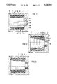
In each of the illustrated embodiments of the invention, a high-current docking plug-connector device consists of a socket component 1 and a pin component 2 which engages with the socket component. The design shown in FIG. 1, in which the pin component 2 is cylindrical in shape, is preferred when rotation of the parts relative to one another is required. Several contact ring groups 3 are positioned axially in succession within the plug socket component 1. In the embodiments shown in FIGS. 1 to 3, each contact ring group 3 consists of a slotted outer socket contact ring 4 with a contact surface 5, which rests elastically on the inner surface of the plug socket component 1, and of a slotted inner socket contact ring 6 with a contact surface 7 resting elastically on the plug pin component 2 in inserted condition. In each embodiment the inner socket contact ring 6 and the outer socket contact ring 4 of each contact ring group 3 are provided with complimentary interfitting tapered contact surfaces 8 and 9. Likewise all depicted embodiments have a socket shoulder 10 inside of the socket component 1; the socket shoulder 10 has a reduced diameter and limits the axial displacement of the contact ring groups 3. To give the contact ring groups a secure mounting in the socket component 1, at least one retainer ring 11 is provided which is attached in an annular groove 12 in the socket component 1.
Diverging from the design shown in FIG. 1--which permits motion of the plug pin component 2 relative to the plug socket component 1 and which employs inner socket contact rings 6 of fitted design which rest against the cylindrically shaped plug pin component 2--the embodiments shown in FIGS. 2, 3, 4, and 5 have non-cylindrical shapes in the area of the plug pin component 2. When high frequencies of insertion are required, the plug-connector device shown in FIG. 2 is suitably provided with a tapered plug pin component which is stepped and for which is provided, contact ring groups 3 with a series of inner socket contact rings 6 of differing diameters. These are in each case fitted to the outer diameter of a corresponding step 13 of the plug pin component 2. In the case of high frequencies of insertion, a plug-connection device can also be employed whose plug pin components have the shape of a truncated cone, as shown in FIG. 3. This arrangement has a series of inner socket contact rings 6 with differing inner diameters, which are fitted to the tapered outer diameter of the pin component.
As can be seen from the drawings, the plug pin component 2 in all embodiments includes a cylindrical guide area 15 which extends beyond the area of contact surface 14. This area marks the installation space for water-free water plug-connectors.
FIGS. 1, 2, and 3 in conjunction with FIGS. 11 and 12 it can be seen that the outer socket contact rings 4 generally comprise a large rotating component with a slot 17 for its elastic positioning on the inner surface of the plug socket component 1.
FIGS. 6 to 8 illustrate the manner in which the plug pin component 2 comes into contact with the plug socket component 1 when the former is inserted into the contact rings 4, 6 of each contact ring group 3. As seen in FIG. 6 the inner socket contact rings 6 initially are somewhat radially inwardly spaced from the outer socket contact rings 4. When the plug pin component 2 is introduced into an inner socket contact ring 6, the latter is moved axially until its outer face 18 rests against the opposing face 19 of the outer socket contact ring 4. The inner ring is then expanded radially until the play, shown in exaggerated form in FIGS. 1, 2, and 3, between the tapered contact surfaces 8 and 9 is substantially eliminated. Current can then flow from the plug pin component 2, over the inner socket contact ring 6 and the face 18 and counter-face 19, to the outer socket contact ring 4, and from there to the plug socket component 1. In the fully inserted state of the pin relative to the socket plug component 1, the number of current conduction areas increases by the number of the contact ring groups 3 which are provided.
FIG. 4 shows an embodiment in which each inner socket contact ring 6 fits between a pair of outer socket contact rings 4. Here each contact ring group 3 thus consists of a inner socket contact ring 6 and two outer socket contact rings 4. The individual contact ring groups 3 are positioned within the plug socket component 1 by means of elastic washers 20, which fit into corresponding annular grooves in the plug socket component 1. The contact rings of each contact ring group 3 are held in place by two corrugated elastic rings 21, which rest on the adjacent elastic rings 20 and 11 or on the socket shoulder 10 and are thus positioned against the outer surface of the plug pin component 2 or the inner surface of the plug socket component 1. From FIG. 4 it can be seen that each inner socket contact ring 6 has two tapered contact surfaces 8, against which the corresponding tapered contact surfaces 9 of the outer socket contact rings 4 are adapted to engage.
In order to increase the force with which an inner socket contact ring 6 presses against the outer surface of the plug pin component 2, each inner socket contact ring 6 in the embodiment shown in FIG. 4 is provided with an elastic ring 22 pressing it radially toward the surface of the plug pin component 2. In the embodiment according to FIG. 4 the elastic ring 22 rests on the outer side of the inner socket contact ring 6.
FIG. 9 shows an embodiment in which the inner socket contact ring 6 has a groove 23, parallel to the ring axis and open to one side, to accommodate the elastic ring 22.
FIGS. 5 and 10 show a modified design, in which the outer socket contact ring 4 of the contact ring group 3 is, in each case formed from a sheet metal strip 24, as shown in greater detail in FIGS. 17 and 18. The strip 24 has punched out tongues 25 which are directed outward from the strip rim. The tongues 25 form the tapered contact surfaces 9 on which the inner socket contact ring 6 rests elastically with its corresponding tapered contact surface 8. The tongues 25 are each stamped out alternately to opposite sides of the strip rim and are angled outwardly. The inner socket contact ring 6 consequently consists of two tapered contact surfaces 8, 8', on which the angled tongues 25 are elastically supported.
In all the embodiments, both the plug socket component 1 and the plug pin component 2 have a central bore 26, by means of which, when the plug connection is created, cooling water can be conducted for diverting heat arising in the area of the electrode holders, or the like. Sealing may be provided by sealing means known to the art and not therefore shown in the drawing.
Claims (11)
1. A water-cooled high-current docking plug-connector device, comprising:
a plug socket component having an inner surface;
a plug pin component removably insertable into said plug socket component for connecting said components together, said components being relatively rotatable when connected;
a contact surface on said plug pin;
a plurality of contact ring groups positioned in axial succession within said plug socket component, each group comprising at least one slotted outer socket contact ring having a contact surface elastically engaging said inner surface of said plug socket component, and at least one slotted inner socket contact ring having a shape to provide a contact surface for engaging elastically said contact surface on said plug pin component when in the inserted position, and mutually engageable tapered contact surfaces on respective outer socket contact and inner socket contact rings of each contact ring group;
an axially extending groove in one side of said at least one inner socket contact ring; and
an elastic ring in said groove urging said at least one inner socket contact ring radially inwardly.
2. A water-cooled high-current docking plug-connector device, comprising:
a plug socket component having an inner surface;
a plug pin component removably insertable into said plug socket component for connecting said components together, said components being relatively rotatable when connected;
a frustoconical contact surface on aid plug pin;
a plurality of contact ring groups positioned in axial succession within said plug socket component, each group comprising at least one slotted outer socket contact ring having a contact surface elastically engaging said inner surface of said plug socket component, and at least one slotted inner socket contact ring having a contact surface for engaging elastically said frustoconical contact surface on said plug pin component when in the inserted position, and mutually engageable tapered contact surfaces on respective outer socket contact and inner socket contact rings of each contact ring group;
an axially extending groove in one side of said at least one inner socket contact ring; and
an elastic ring in said groove urging said at least one inner socket contact ring radially inwardly.
3. A water-cooled high-current docking plug-connector device comprising:
a plug socket component having an inner surface;
a plug pin component removably insertable into said plug socket component for connecting said components together, said components being relatively rotatable when connected;
a frustoconical contact surface on said plug pin; and
a plurality of contact ring groups positioned in axial succession within said plug socket component, each group comprising at least one slotted outer socket contact ring having a contact surface elastically engaging said inner surface of said plug socket component, and at least one slotted inner socket contact ring having a shape to provide a contact surface for engaging elastically said frustoconical contact surface on said plug pin component when in the inserted position, and mutually engageable tapered contact surfaces on respective outer socket contact and inner socket contact rings of each contact ring group;
said at least one outer socket ring of each contact ring group comprising a strip of sheet metal having a plurality of tongues thereon extending out of the plane of said strip at an angle thereto for engaging a respective tapered surface of a respective inner socket contact ring.
4. A device as claimed in claim 3, wherein:
adjacent tongues are angled toward opposite sides of said strip; and
said at least one inner socket contact ring has two oppositely tapered contact surfaces for engaging adjacent tongues respectively.
5. A water-cooled high-current docking plug-connector device, comprising:
a plug socket component having an inner surface;
a plug pin component removably insertable into said plug socket component for connecting said components together, said components being relatively rotatable when connected;
a frustoconical contact surface on said plug pin; and
a plurality of contact ring groups positioned in axial succession within said plug socket component, each group comprising at least one slotted outer socket contact ring having a contact surface elastically engaging said inner surface of said plug socket component, and at least one slotted inner socket contact ring having a shape to provide a contact surface for engaging elastically said frustoconical contact surface on said plug pin component when in the inserted position, and mutually engageable tapered contact surfaces on respective outer socket contact and inner socket contact rings of each contact ring group;
each contact ring group comprising a slotted inner socket contact ring and two slotted outer socket contact rings at least partly embracing said inner contact ring, and oppositely tapered contact surfaces on said inner contact ring for engaging respective tapered contact surfaces on said outer contact rings.
6. A device as claimed in claim 5, and further comprising:
at least one spring means for each contact ring group adjacent to nd acting axially on each contact ring group for urging said respective tapered contact surfaces into contacting position.
7. A device as claimed in claim 6, wherein:
elastic washers are provided between adjacent contact ring groups; and
said spring means comprises two elastic rings interposed between two successive elastic washers.
8. A device as claimed in claim 6, wherein:
said at least one spring means comprises a corrugated elastic ring.
9. A device as claimed in claim 8, wherein:
a plurality of annular grooves are provided in said socket component;
an elastic washer is positioned in each groove; and
one of said elastic rings is positioned on each opposite side of each elastic washer.
10. A water-cooled high-current docking plug-connector device, comprising:
a plug socket component having an inner surface;
a plug pin component removably insertable into said plug socket component for connecting said components together, said components being relatively rotatable when connected;
a frustoconical contact surface on said plug pin;
a plurality of contact ring groups positioned in axial succession within said plug socket component, each group comprising at least one slotted outer socket contact ring having a contact surface elastically engaging said inner surface of said plug socket component, and at least one slotted inner socket contact ring having a shape to provide a contact surface for engaging elastically said frustoconical contact surface on said plug pin component when in the inserted position, and mutually engageable tapered contact surfaces on respective outer socket contact and inner socket contact rings of each contact ring group; and
an elastic ring acting radially upon said at least one inner socket contact ring for urging said at least one inner socket contact ring radially inwardly.
11. A device as claimed in claim 10, wherein:
said inner socket contact ring has a radially outer side; and
said elastic ring engages on said radially outer side.
Applications Claiming Priority (2)
| Application Number | Priority Date | Filing Date | Title |
|---|---|---|---|
| DE3918950 | 1989-06-09 | ||
| DE3918950A DE3918950A1 (en) | 1989-06-09 | 1989-06-09 | WATER COOLED HIGH CURRENT DOCKING CONNECTOR |
Publications (1)
| Publication Number | Publication Date |
|---|---|
| US5080593A true US5080593A (en) | 1992-01-14 |
Family
ID=6382473
Family Applications (1)
| Application Number | Title | Priority Date | Filing Date |
|---|---|---|---|
| US07/532,580 Expired - Fee Related US5080593A (en) | 1989-06-06 | 1990-06-04 | Water-cooled high-current docking plug |
Country Status (7)
| Country | Link |
|---|---|
| US (1) | US5080593A (en) |
| EP (1) | EP0401640B1 (en) |
| JP (1) | JPH0325871A (en) |
| KR (1) | KR910002048A (en) |
| AT (1) | ATE96580T1 (en) |
| DE (2) | DE3918950A1 (en) |
| DK (1) | DK0401640T3 (en) |
Cited By (9)
| Publication number | Priority date | Publication date | Assignee | Title |
|---|---|---|---|---|
| EP0829116A4 (en) * | 1995-06-01 | 1999-01-20 | Elcon Prod Int | Socket contact with arc arresting member |
| US20090239408A1 (en) * | 2008-03-18 | 2009-09-24 | Abb Schweiz Ag | Electrical connection device and connector |
| US9287646B2 (en) | 2010-10-14 | 2016-03-15 | Gregory thomas mark | Actively cooled electrical connection |
| US9543677B1 (en) * | 2015-07-29 | 2017-01-10 | Stein Industries Inc. | Quick connector |
| US20200144798A1 (en) * | 2017-05-08 | 2020-05-07 | Nkt Hv Cables Ab | Pull-In Head For A High Voltage Cable |
| CN113612049A (en) * | 2021-07-29 | 2021-11-05 | 中航光电科技股份有限公司 | Pagoda type contact element |
| US11217928B2 (en) * | 2019-05-03 | 2022-01-04 | Rampart Products Llc | Multi-conductor rotary connector |
| US11296466B2 (en) | 2020-07-30 | 2022-04-05 | The Esab Group Inc. | Coradial connector |
| US12080975B2 (en) | 2021-03-29 | 2024-09-03 | Tbi Industries Gmbh | Multi-diameter power pin and receiving socket |
Families Citing this family (1)
| Publication number | Priority date | Publication date | Assignee | Title |
|---|---|---|---|---|
| DE9401605U1 (en) * | 1994-01-08 | 1994-03-31 | Elektron - Bremen Fabrik für Elektrotechnik GmbH, 28197 Bremen | Connector |
Citations (9)
| Publication number | Priority date | Publication date | Assignee | Title |
|---|---|---|---|---|
| US2533343A (en) * | 1944-11-03 | 1950-12-12 | Bac Fernand Georges | Electric connecting device |
| US2879490A (en) * | 1954-07-21 | 1959-03-24 | Taylor Winfield Corp | Rotary current transfer device |
| US3208025A (en) * | 1962-07-10 | 1965-09-21 | Taylor Winfield Corp | Rotary current transfer device |
| US3972577A (en) * | 1974-09-23 | 1976-08-03 | Etat Francais Represented By Delegation Ministerielle Pour L'armement | Isobaric device with rotating electrical contacts |
| SU951502A1 (en) * | 1980-04-10 | 1982-08-15 | Ордена Ленина И Ордена Трудового Красного Знамени Предприятие П/Я Г-4725 | Electric connector |
| US4405196A (en) * | 1981-01-12 | 1983-09-20 | Fulton Robert W | Electrical connector for high fidelity audio equipment |
| US4507008A (en) * | 1983-05-13 | 1985-03-26 | At&T Bell Laboratories | Stranded cable termination arrangement |
| DE3605076A1 (en) * | 1986-02-18 | 1987-08-20 | Manfred Frankauer | Electrical plug-in contact (jack) |
| US4714441A (en) * | 1987-01-29 | 1987-12-22 | Amp Incorporated | Electrical socket |
Family Cites Families (2)
| Publication number | Priority date | Publication date | Assignee | Title |
|---|---|---|---|---|
| DE2318690C3 (en) * | 1973-04-13 | 1979-01-11 | Leybold-Heraeus Gmbh & Co Kg, 5000 Koeln | Rotatable high current connection |
| US4772233A (en) * | 1983-09-19 | 1988-09-20 | Trilogy Computer Development Partners, Ltd. | Low resistance connector |
-
1989
- 1989-06-09 DE DE3918950A patent/DE3918950A1/en not_active Withdrawn
-
1990
- 1990-05-28 AT AT90110101T patent/ATE96580T1/en not_active IP Right Cessation
- 1990-05-28 EP EP90110101A patent/EP0401640B1/en not_active Expired - Lifetime
- 1990-05-28 DK DK90110101.4T patent/DK0401640T3/en active
- 1990-05-28 DE DE90110101T patent/DE59003196D1/en not_active Expired - Fee Related
- 1990-06-04 US US07/532,580 patent/US5080593A/en not_active Expired - Fee Related
- 1990-06-07 JP JP2149724A patent/JPH0325871A/en active Pending
- 1990-06-07 KR KR1019900008366A patent/KR910002048A/en not_active Abandoned
Patent Citations (9)
| Publication number | Priority date | Publication date | Assignee | Title |
|---|---|---|---|---|
| US2533343A (en) * | 1944-11-03 | 1950-12-12 | Bac Fernand Georges | Electric connecting device |
| US2879490A (en) * | 1954-07-21 | 1959-03-24 | Taylor Winfield Corp | Rotary current transfer device |
| US3208025A (en) * | 1962-07-10 | 1965-09-21 | Taylor Winfield Corp | Rotary current transfer device |
| US3972577A (en) * | 1974-09-23 | 1976-08-03 | Etat Francais Represented By Delegation Ministerielle Pour L'armement | Isobaric device with rotating electrical contacts |
| SU951502A1 (en) * | 1980-04-10 | 1982-08-15 | Ордена Ленина И Ордена Трудового Красного Знамени Предприятие П/Я Г-4725 | Electric connector |
| US4405196A (en) * | 1981-01-12 | 1983-09-20 | Fulton Robert W | Electrical connector for high fidelity audio equipment |
| US4507008A (en) * | 1983-05-13 | 1985-03-26 | At&T Bell Laboratories | Stranded cable termination arrangement |
| DE3605076A1 (en) * | 1986-02-18 | 1987-08-20 | Manfred Frankauer | Electrical plug-in contact (jack) |
| US4714441A (en) * | 1987-01-29 | 1987-12-22 | Amp Incorporated | Electrical socket |
Cited By (16)
| Publication number | Priority date | Publication date | Assignee | Title |
|---|---|---|---|---|
| EP0829116A4 (en) * | 1995-06-01 | 1999-01-20 | Elcon Prod Int | Socket contact with arc arresting member |
| US20090239408A1 (en) * | 2008-03-18 | 2009-09-24 | Abb Schweiz Ag | Electrical connection device and connector |
| US7641506B2 (en) | 2008-03-18 | 2010-01-05 | Abb Schweiz Ag | Electrical connection device and connector |
| US9287646B2 (en) | 2010-10-14 | 2016-03-15 | Gregory thomas mark | Actively cooled electrical connection |
| US9761976B2 (en) | 2010-10-14 | 2017-09-12 | Gregory thomas mark | Actively cooled electrical connection |
| US9543677B1 (en) * | 2015-07-29 | 2017-01-10 | Stein Industries Inc. | Quick connector |
| US20200144798A1 (en) * | 2017-05-08 | 2020-05-07 | Nkt Hv Cables Ab | Pull-In Head For A High Voltage Cable |
| US11011895B2 (en) * | 2017-05-08 | 2021-05-18 | Nkt Hv Cables Ab | Pull-in head for a high voltage cable |
| US11588264B2 (en) | 2019-05-03 | 2023-02-21 | Rampart Products Llc | Multi-conductor rotary connector |
| US11217928B2 (en) * | 2019-05-03 | 2022-01-04 | Rampart Products Llc | Multi-conductor rotary connector |
| EP4189784A1 (en) * | 2020-07-30 | 2023-06-07 | The ESAB Group Inc. | Coradial connector |
| US11296466B2 (en) | 2020-07-30 | 2022-04-05 | The Esab Group Inc. | Coradial connector |
| US12068560B2 (en) | 2020-07-30 | 2024-08-20 | The Esab Group Inc. | Coradial connector |
| US12080975B2 (en) | 2021-03-29 | 2024-09-03 | Tbi Industries Gmbh | Multi-diameter power pin and receiving socket |
| CN113612049A (en) * | 2021-07-29 | 2021-11-05 | 中航光电科技股份有限公司 | Pagoda type contact element |
| CN113612049B (en) * | 2021-07-29 | 2024-09-17 | 中航光电科技股份有限公司 | Pagoda type contact |
Also Published As
| Publication number | Publication date |
|---|---|
| KR910002048A (en) | 1991-01-31 |
| EP0401640B1 (en) | 1993-10-27 |
| ATE96580T1 (en) | 1993-11-15 |
| DK0401640T3 (en) | 1993-12-06 |
| EP0401640A1 (en) | 1990-12-12 |
| DE59003196D1 (en) | 1993-12-02 |
| JPH0325871A (en) | 1991-02-04 |
| DE3918950A1 (en) | 1990-12-13 |
Similar Documents
| Publication | Publication Date | Title |
|---|---|---|
| US5080593A (en) | Water-cooled high-current docking plug | |
| EP1041675B1 (en) | A contact sleeve for electrical communication | |
| US5993254A (en) | Connector for coaxial cables with improved contact-making between connector head and outer cable connector | |
| SU1256701A3 (en) | Pivot assembly | |
| US6135800A (en) | Anti-rotational electrical connector | |
| US4524995A (en) | Swivelable quick connector assembly | |
| US4423892A (en) | Swivelable quick connector assembly | |
| CA2220286A1 (en) | Quick connect/disconnect coupling, together with method and device for its assembly | |
| US5632655A (en) | Electrical connector with replaceable male pins | |
| US4547003A (en) | Pipe connectors | |
| JPH05290902A (en) | Conductor contact device | |
| US4277199A (en) | Keeper assembly | |
| EP0968561B1 (en) | Electrical lead bushing for a turbine generator | |
| US4906211A (en) | Connector for aircraft-to-ground maintenance electrical connection | |
| EP0097324B1 (en) | Clamping assembly for heat exchanger tube plates | |
| CN110030451A (en) | For providing multiple shaft coupling systems fluidly connected | |
| US2300658A (en) | Universal joint | |
| WO1980002059A1 (en) | Keeper assembly | |
| US3251480A (en) | Automatic train line service connector | |
| US20050238420A1 (en) | Coupling device | |
| US4577891A (en) | Torque limiting collar | |
| RU2789079C1 (en) | Junction of parts of the electrical connector | |
| SU1064360A1 (en) | Self-centring electric connector | |
| CN115488399B (en) | Quick-dismantling structure, drilling device and quick-dismantling method | |
| GB2113790A (en) | Improvements in and relating to pipe connectors |
Legal Events
| Date | Code | Title | Description |
|---|---|---|---|
| AS | Assignment |
Owner name: OTTO DUNKEL, GMBH, A CORP. OF THE FED. REP. OF GER Free format text: ASSIGNMENT OF ASSIGNORS INTEREST.;ASSIGNORS:NEUMANN, GERHARD;MOLITOR, PAUL-RAINER;REEL/FRAME:005329/0501 Effective date: 19900504 |
|
| CC | Certificate of correction | ||
| REMI | Maintenance fee reminder mailed | ||
| LAPS | Lapse for failure to pay maintenance fees | ||
| FP | Lapsed due to failure to pay maintenance fee |
Effective date: 19960117 |
|
| STCH | Information on status: patent discontinuation |
Free format text: PATENT EXPIRED DUE TO NONPAYMENT OF MAINTENANCE FEES UNDER 37 CFR 1.362 |