US508038A - The national lithographing c - Google Patents
The national lithographing c Download PDFInfo
- Publication number
- US508038A US508038A US508038DA US508038A US 508038 A US508038 A US 508038A US 508038D A US508038D A US 508038DA US 508038 A US508038 A US 508038A
- Authority
- US
- United States
- Prior art keywords
- tie
- prongs
- rail
- cross
- flexible
- Prior art date
- Legal status (The legal status is an assumption and is not a legal conclusion. Google has not performed a legal analysis and makes no representation as to the accuracy of the status listed.)
- Expired - Lifetime
Links
- 239000002184 metal Substances 0.000 description 5
- 230000008602 contraction Effects 0.000 description 4
- 241001331845 Equus asinus x caballus Species 0.000 description 1
- 208000027418 Wounds and injury Diseases 0.000 description 1
- 238000010276 construction Methods 0.000 description 1
- 230000006378 damage Effects 0.000 description 1
- 239000007943 implant Substances 0.000 description 1
- 208000014674 injury Diseases 0.000 description 1
- 238000009740 moulding (composite fabrication) Methods 0.000 description 1
- 238000004904 shortening Methods 0.000 description 1
- MLGCXEBRWGEOQX-UHFFFAOYSA-N tetradifon Chemical compound C1=CC(Cl)=CC=C1S(=O)(=O)C1=CC(Cl)=C(Cl)C=C1Cl MLGCXEBRWGEOQX-UHFFFAOYSA-N 0.000 description 1
Images
Classifications
-
- E—FIXED CONSTRUCTIONS
- E01—CONSTRUCTION OF ROADS, RAILWAYS, OR BRIDGES
- E01B—PERMANENT WAY; PERMANENT-WAY TOOLS; MACHINES FOR MAKING RAILWAYS OF ALL KINDS
- E01B3/00—Transverse or longitudinal sleepers; Other means resting directly on the ballastway for supporting rails
- E01B3/16—Transverse or longitudinal sleepers; Other means resting directly on the ballastway for supporting rails made from steel
Definitions
- the object of this invention is't rigidly unite iiae track-rails to metallic .orose-tiee, while-providing, e1: the same time, suitable means to permit; of expansion angi contraction in the iengths of the rails unde: changes if; of atmospheric temperature.
- This object is attained by means of the constructions 110w co-be described.
- Figure 1 shows in' plan a pals-i. of railroad track em- I 2'0 bodying my invention.
- Fig. 4 shows a transverse sectional g5 elevation Taken through the iinezflzflof Fig. 2.
- Fig. 5 is. a transverse section, eoierged, taken through the line X, of Figs. 1,6 and 7.
- Figslfi and 7 are views in plan or parts of IvLih'OaLi tracks
- a metal cross tie formed of a single piece of metal, the ends of s'eid tie being a bent flexible prong or pronge.
- a twopnrt-rail having its parts wzlclcd to diiferenl; members of a metal croes'tie, said members of the tie being expcnsibie lengthwise of the track.
- a otwo pm't-q'nil having its parts welded to diiierontimombersof e nietclcroesdie, said members of the cross-tie being flexible or elastic lengihwiee of the rail.
Landscapes
- Engineering & Computer Science (AREA)
- Architecture (AREA)
- Civil Engineering (AREA)
- Structural Engineering (AREA)
- Prostheses (AREA)
- Transmissions By Endless Flexible Members (AREA)
- Length Measuring Devices With Unspecified Measuring Means (AREA)
Description
' (No Model.) 2 SheetsSheet 1.
A. J. MOXHANL. RAILROAD TRAUK.
No.. 508,038. Patented Nov. 7, 1893.
w i I W Illilll lllllllliilH' ii I:
7 IIIIIIIIIIIIIIIIIIHIL 4-. e I. 9 t
i fi WITNESSES: INVENTOH ATTOHNE Y.
2 Sheets W-S heet 2.
(No Model.)
a. MOXHAM.
RAILROAD TRAOK.
Patented Nov 7, 1893.
wlrrmssz s IN VE N TOR 35., scribed as follows:
Wee fiifiree ARTHURJ; zeoxeiii QB .io i ie'rowm v Re? t me J ohxistowu ,in the county of Cembrie and State of Pennsylvania; have invented e new and 5 useful Improvement in tile Ari of Constructiug Railroad-Tracks, which invention or improvement is fully set forth and illustrated in the foiiowiug epooifioeiiou and. aceoiiipeny ing drawings. 5 o
The object of this invention is't rigidly unite iiae track-rails to metallic .orose-tiee, while-providing, e1: the same time, suitable means to permit; of expansion angi contraction in the iengths of the rails unde: changes if; of atmospheric temperature. This object is attained by means of the constructions 110w co-be described.
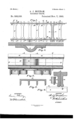
iii the accompanying drawings, Figure 1, shows in' plan a pals-i. of railroad track em- I 2'0 bodying my invention. Fi 2 sbowe'lin sideelevation, enlarged; a vertioei Section taken at the line a, z, of Fig. i. Fig. 3; isehorizontel seotionfmiken through the line "L, r 5 of F g. 2. Fig. 4, shows a transverse sectional g5 elevation Taken through the iinezflzflof Fig. 2.
Fig. 5; is. a transverse section, eoierged, taken through the line X, of Figs. 1,6 and 7.
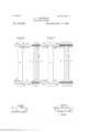
Figslfi and 7 are views in plan or parts of IvLih'OaLi tracks,
showing modified forms of 30 oroee-ties which may be used in carrying out my invention.
In said figures, the several. parts are indicated by reference letters, by the aid of which said parts and the invention will now be do Referringfirst to .35 ige. l to 5 irieiusive,'ti1e treek-raiie A are composed of ewe-parts oi, e, which parts-overlap eeeh other so as to break i jQiliiS and time form a practically comfiin'c oi s 0' ireii. .,fThe contiguous, or meeting, ende of email pert-rail are oonn eoted by splice-hers I3, Welded to eech of eeici -perte,-oea;r'oeid ends, .eo limit each port-rail bee seen: 115. 420.9%. m me 1.)
also serve to firmiy implant zhe tie e in the ground or in the haiiest which may be empioyeci. Tiieends of the oroeeties C are forked as shown at the poini'e e, a, which iet tors indicate bifurcations or prongs. The rails A cross eeiii bifurcations em: each part a, a; of the miieie weici ed to one prom: of eaoh oroe-tie, as. seen as g, h, Figs. 1 enni By mezms of suitable apparatus, these Weiding operaiions oen be eifeoized partly in the course of the laying of the, track and petrtiy at the Works previous ito siiipmentes may be deemed been y In Figs. 6 and Z are shown modified form's having a. portion -chereof bent to form the hooked endioir bent prong j, the parts a p,
omitted. iii? the points M. In Fig. 7, the riefi is shown having poriione t-hereoi;ioent to form ing welded to said. prongs at she poinie h iie'C, shown in' the other figures. It oeu iie readily seen, eufiicient flexib lity being given to the prongs or bifuroei ed ende oi the eraseties, that said; ends will yield or flex wiikiziie izinuous, integrei, line 0's creek ie provided which oan'expzmd end oontmot ruption of its alignment am'i also without qiietiirbfng tile mam body of the cross-tie; the
expensive motion; A" smooth,ebroug iumhie tre'ek and road bed ere time previfleni we gen 1 oij eroee-ties-whioizmmy be used in. carryingoizi; my invention. in Fig. 6 the tie J is shown mohmeni; between. ii e rail end'tie may be and g','respee'tiveiy. The body of me ties}, J, are substantially similar to the body oiisiie'j reiis, and time a. rigid preotioeiiyeom whieiiyineor'e easy motion Jo iiio seize, e'omfore. "io passengers tii'ereen, anti. oeeii Wee-2' emiimdereides, Wiih. 'ibl'igiiiidiilbi ribs, which Seeuro sreugiii and etifineee-wiii lightness and.
of the rail being Welded to the tie eeiiie the prongs 2', 1., the parts a, a, of we reii beoree iing or elongation and shortening of the under veeyy 'ing temperatures, Without injury to on disv Having time fully described my invention. 1 clnim-- i. metal cross-tic, the ends oi amid cross iio being, flexible or elasiic and cm tie inelastic intermediate to said ends.
2. A metal cross tie formed of a single piece of metal, the ends of s'eid tie being a bent flexible prong or pronge.
3. A metal cross lie having flexible and elastic bifurcated ends. I
The combination of a two-part-rail nnrl a. metallic cross-tie, each of the ports, of said rail being welded to said cross-tie.
'two arts of said rail bein welded to said 5. A twopnrt-rail having its parts wzlclcd to diiferenl; members of a metal croes'tie, said members of the tie being expcnsibie lengthwise of the track. j
6. A otwo pm't-q'nil, having its parts welded to diiierontimombersof e nietclcroesdie, said members of the cross-tie being flexible or elastic lengihwiee of the rail.
7. The combination of n twoqmrt mil h'zwing broken joints and a metallic crossiie, the
cross-tie.
8. The combination of a uvo-pnrt-mil and a metallic cross-tic having a prong or prongs at its ends, ench of the ports of said rail beimp; secured to one of the prongs of said Lie.
9. The combination with railroad reilennd accuse flexible expansion and contraction pieces-s eecnrcd at their mule, cl :1- nicinillic croiss'mo halving at its cmis flexible crioneione on,
which the rails rest. eeiil tie being connect. to the rails. v
10. The conibi'mition of n inctnllic owes-tie having a flexible prong; or prongs a l. its Guile; mils seen red to said ends; and flexible expansion and cont-rzwtion pieces seem-cal at the ende oi Still]. rniie.
11. The combination of n metallic cross-Lie having a, prong or prongs M; itc curls; a twopzirt-rnil having each of ite pin 3 scoured to one of said pronye; Hill n flexible eripnnsion our contraction piece secured at the ends of one part of coil} mil.
1:. A rnill'oml tmch minsieiing of lilo followicg niunorl clczncnie in combination: metallic (arose-lie: cnch iii-wing n prong or prongs at he cni'ie; Ln'o pnmlici liiiiS,0ilCil construct- Gil of two partmunl hnvingench of said parts welded to dii'l'crcnt prongs oi the ends of snicl tics; and flexible expansion and contraction pieces wchlcrl iii the contiguous curls of swirl rails.
filial 1 [ii H J. 'lIUKllA M.
Witnesses:
ll, (3. Era-ire F. iiirfiimwxwr
Publications (1)
| Publication Number | Publication Date |
|---|---|
| US508038A true US508038A (en) | 1893-11-07 |
Family
ID=2576868
Family Applications (1)
| Application Number | Title | Priority Date | Filing Date |
|---|---|---|---|
| US508038D Expired - Lifetime US508038A (en) | The national lithographing c |
Country Status (1)
| Country | Link |
|---|---|
| US (1) | US508038A (en) |
-
0
- US US508038D patent/US508038A/en not_active Expired - Lifetime
Similar Documents
| Publication | Publication Date | Title |
|---|---|---|
| US508038A (en) | The national lithographing c | |
| US824271A (en) | Portable railway crossover-switch. | |
| US149990A (en) | Improvement in railway-switches | |
| US790010A (en) | Railway-switch construction. | |
| US507595A (en) | Ville | |
| US551649A (en) | Construction of railway-tracks | |
| US528950A (en) | Railway-rail | |
| US510295A (en) | rideal | |
| US1295771A (en) | Railroad-tie. | |
| US184968A (en) | Improvement in elevated railways | |
| US1011811A (en) | Railroad-rail. | |
| US431253A (en) | Railway-rail bed | |
| US541259A (en) | Rail-bond | |
| US722175A (en) | Rail joint and fastening. | |
| US973459A (en) | Metallic tie and rail-fastener. | |
| US443714A (en) | Bridge | |
| US724064A (en) | Railroad-rail-fastening device. | |
| US397385A (en) | Cable or electric street-railway | |
| US504067A (en) | Frank s | |
| US838573A (en) | Composite metal-and-wood tie for railway-tracks. | |
| US1286011A (en) | Railroad-tie. | |
| US475233A (en) | George w | |
| US284668A (en) | putnam | |
| US756660A (en) | Combined railway-tie and rail-fastening. | |
| US492848A (en) | Railway-rail joint |