US507732A - Switch for trolley-wires - Google Patents
Switch for trolley-wires Download PDFInfo
- Publication number
- US507732A US507732A US507732DA US507732A US 507732 A US507732 A US 507732A US 507732D A US507732D A US 507732DA US 507732 A US507732 A US 507732A
- Authority
- US
- United States
- Prior art keywords
- trolley
- wires
- flanges
- switch
- openings
- Prior art date
- Legal status (The legal status is an assumption and is not a legal conclusion. Google has not performed a legal analysis and makes no representation as to the accuracy of the status listed.)
- Expired - Lifetime
Links
- 238000010276 construction Methods 0.000 description 1
Images
Classifications
-
- B—PERFORMING OPERATIONS; TRANSPORTING
- B60—VEHICLES IN GENERAL
- B60M—POWER SUPPLY LINES, AND DEVICES ALONG RAILS, FOR ELECTRICALLY- PROPELLED VEHICLES
- B60M1/00—Power supply lines for contact with collector on vehicle
- B60M1/12—Trolley lines; Accessories therefor
- B60M1/14—Crossings; Points
Definitions
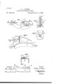
- My invention relates to improvements in devices for attachment to trolley wires, to serve as guides ilor the trolley or contacting device, when passing from one wire to another. I attain this object by the constructions shown in the accompanying drawings, in. which- Figure l is a perspective view of a device embodying myinvention. Fig. 2 isaperspective view of the same in an inverted position. Figs; 3 to 6 inclusive,are details of the same.
- a represents the main body of the switch, which consists essentially of a curved plate, having downwardly projecting flanges a, a on opposite sides thereof.
- the main body of the device is formed of a substantially triangular shape, and the flanges a, a approach each other at one end to form an opening a between the same, and at the other end they diverge, and auxiliary flanges a 0. are provided to form openings a a
- the trolley wires 6, 12', b extend into the respective openings a a M.
- the top portion of the switch device is provided with slotted openings 0, c, 0 through which the wires b, b, b are inserted; the wires being adapted to extend in through said slotted openings, so that the bottom of each of the wires shall stand substantially tangent to the curved top of the switch.
- a clamp At or near the end of each of these slotted openings is a clamp, each of which consists essentially of a projecting lug d, and a curved jaw d; a clamping screw 01 being adapted to extend through the lug d, so as to engage with the trolley wire, which is placed between the lugs d, and the jaw d, and thus hold the same firmly in its position.
- a a stud e in which is mounted a roller bearing 6'; said stud being provided with a cone-shaped top e adapted to form a shoulder to support the top of the roller e, the lower portion of said stud being projected through the top of the switch and secured therein bya not a or other suitable fastening device.
- This roller bearing e turning as it does at the juncture of the flanges a a serves to guide the trolley wheel in its position from one trolley wire to the other.
- the clamping devices for holding the ends of the trolley wire serve the purpose of readily adjusting the wires through the same if it should become necessary.
- I claim- 1 In a switch for trolley wires, a triangularly shaped body having a curved top and projecting flanges on opposite sides thereof, auxiliary flanges adjacent to said main flanges to .form openings, as described, a projecting post at the junction of said auxiliary flanges, and a roller bearing on said post, substantially as specified.
- a switch body having a curved top and downwardly projecting flanges, auxiliary flanges adjacent to one end of the respective flanges to form openings, as described, slotted- 8 5 openings in the top of said body portion adapted to receive the trolley wires which extend substantially tangent to said curved top, and clamping devices at the ends of said slotted openings, substantially as and for the purpose specified.
Landscapes
- Engineering & Computer Science (AREA)
- Mechanical Engineering (AREA)
- Current-Collector Devices For Electrically Propelled Vehicles (AREA)
Description
(N0 Mod-2J1.)
' G. A. HUBEN.
SWITCH FOR TROLLEY WIRES.
No. 507,732. Patented Oct. 31,1893.
I UNITED STATES PATENT OFFICE.
GUSTAVUS A. HUBEN, OF SPRINGFIELD, OHIO.
SWITCH FOR TROLLEY-WIRES.
SPECIFICATION forming part of Letters Patent No. 507,732, dated October 31, 1893.
Application filed July 29,1893. Serial No. 481,810. (No model.)
To aZZ whom it may concern.-
Be it known that I, GUSTAVUS A. HUBEN, a citizen of. the United States, residing at Springfield, in the county of Clark and State of Ohio, have inventeda certain new and use- :ful Improvement in Switches for Trolley- Wires, of which the following is a specification.
My invention relates to improvements in devices for attachment to trolley wires, to serve as guides ilor the trolley or contacting device, when passing from one wire to another. I attain this object by the constructions shown in the accompanying drawings, in. which- Figure l is a perspective view of a device embodying myinvention. Fig. 2 isaperspective view of the same in an inverted position. Figs; 3 to 6 inclusive,are details of the same.
Like parts are represented by similar letters of reference in the several views.
In the said drawings a, represents the main body of the switch, which consists essentially of a curved plate, having downwardly projecting flanges a, a on opposite sides thereof. The main body of the device is formed of a substantially triangular shape, and the flanges a, a approach each other at one end to form an opening a between the same, and at the other end they diverge, and auxiliary flanges a 0. are provided to form openings a a The trolley wires 6, 12', b extend into the respective openings a a M. The top portion of the switch device is provided with slotted openings 0, c, 0 through which the wires b, b, b are inserted; the wires being adapted to extend in through said slotted openings, so that the bottom of each of the wires shall stand substantially tangent to the curved top of the switch. At or near the end of each of these slotted openings is a clamp, each of which consists essentially of a projecting lug d, and a curved jaw d; a clamping screw 01 being adapted to extend through the lug d, so as to engage with the trolley wire, which is placed between the lugs d, and the jaw d, and thus hold the same firmly in its position.
In order to further insure the proper travel of the trolley Wheel, in passing from one of the trolley wires to the other, I place at the juncture of the flanges a, a a stud e, in which is mounted a roller bearing 6'; said stud being provided with a cone-shaped top e adapted to form a shoulder to support the top of the roller e, the lower portion of said stud being projected through the top of the switch and secured therein bya not a or other suitable fastening device. This roller bearing e, turning as it does at the juncture of the flanges a a serves to guide the trolley wheel in its position from one trolley wire to the other. The surface of the top a, being curved, and the wires being formed substantially tangent thereto, the trolley wheel engages with the trolley wire before its flanges have left the curved surfaces of the switch, so that the proper contact is insured. The clamping devices for holding the ends of the trolley wire serve the purpose of readily adjusting the wires through the same if it should become necessary.
Having thus described my invention, I claim- 1. In a switch for trolley wires, a triangularly shaped body having a curved top and projecting flanges on opposite sides thereof, auxiliary flanges adjacent to said main flanges to .form openings, as described, a projecting post at the junction of said auxiliary flanges, and a roller bearing on said post, substantially as specified.
2. A switch body having a curved top and downwardly projecting flanges, auxiliary flanges adjacent to one end of the respective flanges to form openings, as described, slotted- 8 5 openings in the top of said body portion adapted to receive the trolley wires which extend substantially tangent to said curved top, and clamping devices at the ends of said slotted openings, substantially as and for the purpose specified.
3. The combination with the curved body having the projecting flanges arranged approximate to each other at one end, and auxiliary flanges arranged between the said main flanges at the opposite end, a revolving post placed at the junction of said auxiliary flanges, slotted openings at the respective openings formed by said flanges, a projecting jaw on one side of each of said openings and a lug on the other, and a set screw passing through said lug and adapted to engage the trolley wire and impinge it against said jaw, substantially as specified.
GUSTAVUS A. I-IUBEN.
In presence of.-
OLIVER H. MILLER, FRANK WATT.
Publications (1)
| Publication Number | Publication Date |
|---|---|
| US507732A true US507732A (en) | 1893-10-31 |
Family
ID=2576564
Family Applications (1)
| Application Number | Title | Priority Date | Filing Date |
|---|---|---|---|
| US507732D Expired - Lifetime US507732A (en) | Switch for trolley-wires |
Country Status (1)
| Country | Link |
|---|---|
| US (1) | US507732A (en) |
-
0
- US US507732D patent/US507732A/en not_active Expired - Lifetime
Similar Documents
| Publication | Publication Date | Title |
|---|---|---|
| US507732A (en) | Switch for trolley-wires | |
| US430926A (en) | Suspending device for electric conducting-wires | |
| US507733A (en) | Trolley for electric railways | |
| US765974A (en) | Trolley-wire clip. | |
| US536250A (en) | Adjustable switch for trolley systems | |
| US774534A (en) | Trolley. | |
| US477781A (en) | Joseph sachs | |
| US1511379A (en) | Wire-retaining device | |
| US453100A (en) | Insulating-clamp for span-wires | |
| US396196A (en) | Insulator-support for electric conductors | |
| US985430A (en) | Shoe for third-rail electric cars. | |
| US909569A (en) | Trolley-wire support or hanger. | |
| US775993A (en) | Guard for trolleys. | |
| US1009767A (en) | Shoe for third-rail electric cars. | |
| US659823A (en) | Suspending device for trolley-wires. | |
| US633182A (en) | Adjustable crossover for electric wires. | |
| US568060A (en) | Insulator | |
| US886645A (en) | Trolley-guard. | |
| US1008913A (en) | Collector for traveling cranes and the like. | |
| US1017462A (en) | Frog for trolleys. | |
| US499461A (en) | Overhead-trolley-wire switch | |
| US445594A (en) | Electric-conductor support | |
| US520971A (en) | Miller a | |
| US1066008A (en) | Trolley catcher or guard. | |
| US1183073A (en) | Section-insulator. |