US5073263A - Method and article for restraining extrusion of feed spacers and circumferential expansion in spiral filtration modules - Google Patents
Method and article for restraining extrusion of feed spacers and circumferential expansion in spiral filtration modules Download PDFInfo
- Publication number
- US5073263A US5073263A US07/586,578 US58657890A US5073263A US 5073263 A US5073263 A US 5073263A US 58657890 A US58657890 A US 58657890A US 5073263 A US5073263 A US 5073263A
- Authority
- US
- United States
- Prior art keywords
- outerwrap
- module
- leaves
- around
- spacer
- Prior art date
- Legal status (The legal status is an assumption and is not a legal conclusion. Google has not performed a legal analysis and makes no representation as to the accuracy of the status listed.)
- Expired - Lifetime
Links
- 125000006850 spacer group Chemical group 0.000 title claims abstract description 42
- 238000000034 method Methods 0.000 title claims abstract description 16
- 238000001914 filtration Methods 0.000 title claims description 16
- 230000000452 restraining effect Effects 0.000 title abstract description 10
- 238000001125 extrusion Methods 0.000 title description 10
- 239000012528 membrane Substances 0.000 claims abstract description 24
- 239000012530 fluid Substances 0.000 claims abstract description 16
- 239000012466 permeate Substances 0.000 claims abstract description 12
- 239000002654 heat shrinkable material Substances 0.000 claims abstract 2
- 239000000706 filtrate Substances 0.000 claims description 4
- 239000012815 thermoplastic material Substances 0.000 claims description 3
- 238000003466 welding Methods 0.000 claims 1
- 238000000108 ultra-filtration Methods 0.000 abstract description 12
- 239000000463 material Substances 0.000 description 11
- 239000000203 mixture Substances 0.000 description 3
- -1 polytetrafluoroethylene Polymers 0.000 description 3
- 238000010276 construction Methods 0.000 description 2
- 238000009295 crossflow filtration Methods 0.000 description 2
- 238000001471 micro-filtration Methods 0.000 description 2
- 238000001223 reverse osmosis Methods 0.000 description 2
- 239000004593 Epoxy Substances 0.000 description 1
- 239000004698 Polyethylene Substances 0.000 description 1
- 239000004743 Polypropylene Substances 0.000 description 1
- 238000004026 adhesive bonding Methods 0.000 description 1
- 230000002411 adverse Effects 0.000 description 1
- 238000013461 design Methods 0.000 description 1
- 238000005516 engineering process Methods 0.000 description 1
- 238000007689 inspection Methods 0.000 description 1
- 238000009434 installation Methods 0.000 description 1
- 210000004779 membrane envelope Anatomy 0.000 description 1
- 238000012986 modification Methods 0.000 description 1
- 230000004048 modification Effects 0.000 description 1
- 229920000728 polyester Polymers 0.000 description 1
- 229920000573 polyethylene Polymers 0.000 description 1
- 229920000642 polymer Polymers 0.000 description 1
- 229920000098 polyolefin Polymers 0.000 description 1
- 229920001155 polypropylene Polymers 0.000 description 1
- 229920001343 polytetrafluoroethylene Polymers 0.000 description 1
- 239000004810 polytetrafluoroethylene Substances 0.000 description 1
- 238000012545 processing Methods 0.000 description 1
- 239000000126 substance Substances 0.000 description 1
- 238000012360 testing method Methods 0.000 description 1
Images

Classifications
-
- B—PERFORMING OPERATIONS; TRANSPORTING
- B01—PHYSICAL OR CHEMICAL PROCESSES OR APPARATUS IN GENERAL
- B01D—SEPARATION
- B01D63/00—Apparatus in general for separation processes using semi-permeable membranes
- B01D63/10—Spiral-wound membrane modules
- B01D63/107—Specific properties of the central tube or the permeate channel
Definitions
- This invention relates generally to ultrafiltration technology and, more specifically, to a spiral wound filtration module for use in cross flow filtration and method of constructing same.
- a typical design for an ultrafiltration device is to provide a spiral wrapped filtration module.
- Such a module is made by providing a permeate tube around which is wound one or more permeate envelopes or membrane leaves. These membrane leaves are separated by feed spacer screens.
- the spirally wound leaves have heretofore been held in place by a bypass spacer screen which is fused to the outside end of one layer of the feed spacer screen.
- the bypass screen is then wound around the circumference of the assembled leaves and ultimately fused to itself to complete the module.
- the module is loaded into a housing or pressure vessel and operated at a slight pressure drop across the module.
- Normal flow conditions also include temperatures in the range of 80°-140° F.
- a combination of the hydraulic forces exerted on the module and the heat from the processing operation have a tendency to soften the thermoplastic materials utilized as the bypass and feed spacer screens. This may cause the spiral to loosen reducing the frictional forces holding successive material layers and ultimately causing the feed spacer screen to extrude.
- Such extrusion can lead to sanitation problems and low operating efficiency caused by low flow regions attributable to the extrusion problem.
- the increase in outer diameter which results from the extrusion also makes the modules difficult to remove for replacement, inspection or testing.
- an object of the present invention to provide an ultrafiltration module and method of constructing same which substantially precludes feed spacer extrusion and circumferential expansion by circumscribing the module with one or more restraining bands.
- Another object of the invention is to provide an ultrafiltration module which is not subject to feed spacer extrusion or circumferential expansion and a method of constructing same which will not require modification of existing pressure vessels that comprise a part of typical filtration systems.
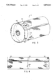
- FIG. 1 is a perspective view of a filtration module constructed according to the present invention
- FIG. 2 is a perspective view of the module shown in FIG. 1 after the membrane leaves have been wound around the permeate tube and the bypass spacer screen has been placed;
- FIG. 3 is another perspective view of the completed filtration module according to the present invention with portions broken away to illustrate details of construction
- FIG. 4 is a side elevational view of the module according to the present invention.
- a filtration module is designated generally by the numeral 10 (FIG. 3) and comprises an elongated permeate collection tube 12 having a plurality of holes 14 in the tube wall.
- each leaf 16 will normally comprise two ultrafiltration membrane sheets separated by a permeate collection sheet which may be an open mesh screen material formed from an inert composition.
- the leaves are secured to the tube at the opposite ends of the latter by gluing.
- the membrane leaf is wrapped around tube 12 to form a plurality of layers, the layers are separated by a feed spacer screen 18 through which fluid can easily pass as a result of the open mesh construction.
- the length of screen 18 which separates the membrane leaves is preferably selected so that it will extend at least to the terminal end 17 of the underlying leaf.
- outerwrap 20 is presented by four feed spacer screens which extend beyond the terminal ends of the underlying membrane leaves and overlap each other to present an outerwrap that completely circumscribes the spirally wound leaves.
- bands 22 are sized to be slightly larger in diameter than the outside diameter of outerwrap 20 so that the bands can be easily moved into position on the module.
- Bands 22 are preferably constructed from a heat shrinkable composition such as polytetrafluoroethylene polymer which will respond at temperatures of between 750°-1000° F. applied in a localized fashion while slowly rotating the module. A typical module will require a total time of three to five minutes to completely shrink each band diameter by 10-15%.
- a final bypass spacer screen 24 is attached to the outerwrap 20 in a manner so as to overlie restraining bands 22.
- Screen 24 is another sheet of open mesh material. This screen is fused to the outerwrap 20 (except for the areas where bands 22 are located) and then spirally wound around the circumference of the module assembly overlapping itself slightly before terminating. The bypass screen 24 is then fused to itself in the overlap area which fused area is designated by the numeral 25 in FIGS. 3 and 4.
- bypass screen 24 is fused to the outerwrap 20 at spaced apart locations designated by the numeral 26 on either side of bands 22 and circumferentially spaced around the perimeter of the assembled module 10.
- the fused areas 26 serve to lock bands 22 in place against movement in an axial direction along the spiral assembly.
- a fluid to be filtered is introduced as feed stock at one end of the housing (not shown) into which module 10 is adapted to be inserted.
- This feed stock passes in a axial direction along the channels created by the feed channel spacer screens 18.
- the permeate fraction may then enter the membrane material of the individual leaves 16 and eventually will be discharged from the membrane envelope and enter tube 12 through openings 14.
- the filtrate will continue to flow axially and will be removed through a separate filtrate outlet of the housing.
- bands 22 are not capable of passing fluid, they are surrounded on all sides by screen material (outerwrap 20 and bypass screen 24) which will assure continual passage of fluid over the band surfaces thus maintaining hygienic integrity.
- bands 22 are of a sufficient strength so as to retain the original diameter of the module assembly notwithstanding the tendency of the feed spacer screen material to extrude under the operating conditions previously discussed.
- the present invention also encompasses a method of constructing a spiral wound filtration module by providing a longitudinally extending permeate carrier tube, providing at least one filtration membrane leaf, providing a fluid passable spacer means on top of said membrane leaf, attaching the leaf to the tube in a manner well known to those skilled in the art, followed by wrapping the membrane leaf and the spacer means around the tube to present a plurality of spaced membrane layers.
- the length of the spacer means is selected so that it will extend at least to the terminal end of the outermost layer of the membrane leaf and, preferably, beyond the ends of the leaves sufficiently to form an outerwrap screen which surrounds the wound leaves.
- a plurality of restraining bands are tightly secured around the outerwrap at longitudinally spaced apart locations to hold the wound layers and the outerwrap in place.
- a fluid passable spacer means is then wrapped around the restraining bands and the outerwrap to assure the presence of a fluid passable surface on all sides of the restraining bands 22.
- the spacer screen 24 is secured in place by overlapping onto itself and fusing the overlapped portions together to present the completed module assembly.
- the bypass spacer screen is also fused to the outerwrap at circumferentially spaced locations on either side of bands 22 so as to lock the bands in place and preclude axial movement in either direction.
- the mesh material which is utilized for the feed spacer screen 18, the outerwrap 20 and the bypass spacer screen 24 may be made of various inert compositions well known to those skilled in the art. Typical materials include high and low density polyolefins, such as polyethylene, polypropylene or polyester. NylonTM (Reg. TM) and other materials having comparable characteristics are also acceptable.
- the bands 22 may be constructed from various materials so long as the material is unreactive with the substance being filtered and is also capable of being tightly engaged with the spiral wound assembly. Likewise, the number of bands and the spacing (if any) between bands can be varied to meet the operating requirements or economics of a particular filtration module. While a plurality of bands in spaced relationship will normally be utilized, a single wide band may be suitable for a particular installation.
- outerwrap 20 by extending feed spacer screens beyond the terminal ends of the respective underlying leaves, it would also be possible to form the outerwrap by a separate screen which is fused to a feed spacer screen and then wound around the circumference of the spirally wound leaves.
- the method and device of the present invention are applicable to various types of cross flow filtration including ultrafiltration, microfiltration and reverse osmosis.
Landscapes
- Chemical & Material Sciences (AREA)
- Chemical Kinetics & Catalysis (AREA)
- Separation Using Semi-Permeable Membranes (AREA)
- Filtering Materials (AREA)
Abstract
An ultrafiltration module and method of constructing same is the subject of the present invention. The module comprises a permeate collector tube and one or more membrane leaves wound around the tube together with a feed channel spacer so as to present spaced layers of membrane leaves or envelopes that are contacted by fluid flowing axially through the module in the channel provided by the feed spacer screen. The feed spacer screen projects beyond the terminal ends of the leaves to present an open mesh outerwrap screen circumscribing the wound leaves. A plurality of restraining bands are provided in longitudinally spaced relationship along the length of the module. These bands are designed to hold the entire module assembly in tight spiral relationship. Preferably, the bands are constructed of heat shrinkable material and are thus secured in place and tightened by the application of heat. After the restraining bands are in place, a bypass screen also of open mesh configuration is wrapped around the outerwrap and the restraining bands and secured by overlapping it onto itself and fusing the overlapped portion.
Description
This invention relates generally to ultrafiltration technology and, more specifically, to a spiral wound filtration module for use in cross flow filtration and method of constructing same.
Semi-permeable membranes are utilized in both high pressure reverse osmosis and low pressure ultrafiltration and microfiltration processes. A typical design for an ultrafiltration device is to provide a spiral wrapped filtration module. Such a module is made by providing a permeate tube around which is wound one or more permeate envelopes or membrane leaves. These membrane leaves are separated by feed spacer screens. The spirally wound leaves have heretofore been held in place by a bypass spacer screen which is fused to the outside end of one layer of the feed spacer screen. The bypass screen is then wound around the circumference of the assembled leaves and ultimately fused to itself to complete the module.
The module is loaded into a housing or pressure vessel and operated at a slight pressure drop across the module. Normal flow conditions also include temperatures in the range of 80°-140° F. A combination of the hydraulic forces exerted on the module and the heat from the processing operation have a tendency to soften the thermoplastic materials utilized as the bypass and feed spacer screens. This may cause the spiral to loosen reducing the frictional forces holding successive material layers and ultimately causing the feed spacer screen to extrude. Such extrusion can lead to sanitation problems and low operating efficiency caused by low flow regions attributable to the extrusion problem. The increase in outer diameter which results from the extrusion also makes the modules difficult to remove for replacement, inspection or testing.
As far as is known, there has been no prior attempt to reduce or eliminate feed spacer extrusion or circumferential expansion in spiral wound ultrafiltration modules of the type described. For non-sanitary applications, the problem is avoided by an overwrap such as fiberglass-reinforced epoxy that is allowed to harden and form a rigid outer shell for the module. This is unacceptable in sanitary applications or other uses where no stagnant flow areas are permissible since stagnant flow is inherent along the surface of the hardened outer shell.
It is, therefore, an object of the present invention to provide an ultrafiltration module and method of constructing same which substantially precludes feed spacer extrusion and circumferential expansion by circumscribing the module with one or more restraining bands.
As a corollary to the above object, it is an objective of this invention to substantially reduce or eliminate feed spacer extrusion and circumferential expansion without creating dead space which would adversely impact hygienic conditions or reduce operating efficiency.
Another object of the invention is to provide an ultrafiltration module which is not subject to feed spacer extrusion or circumferential expansion and a method of constructing same which will not require modification of existing pressure vessels that comprise a part of typical filtration systems.
It is also one of the objectives of our invention to provide an ultrafiltration module and method of constructing it which will not undergo significant feed spacer extrusion or circumferential expansion and which can be utilized with modules having one or a plurality of membrane leaves.
Other objects of the invention will be made clear or become apparent from the following description and claims when read in light of the accompanying drawings wherein:
FIG. 1 is a perspective view of a filtration module constructed according to the present invention;
FIG. 2 is a perspective view of the module shown in FIG. 1 after the membrane leaves have been wound around the permeate tube and the bypass spacer screen has been placed;
FIG. 3 is another perspective view of the completed filtration module according to the present invention with portions broken away to illustrate details of construction; and
FIG. 4 is a side elevational view of the module according to the present invention.
Referring initially to FIGS. 1 and 3, a filtration module is designated generally by the numeral 10 (FIG. 3) and comprises an elongated permeate collection tube 12 having a plurality of holes 14 in the tube wall.
It is well known to those skilled in the art to provide an ultrafiltration module by spirally wrapping a plurality of ultrafiltration envelopes or leaves 16 circumferentially around tube 12 in the manner illustrated in FIG. 1. Each leaf 16 will normally comprise two ultrafiltration membrane sheets separated by a permeate collection sheet which may be an open mesh screen material formed from an inert composition. The leaves are secured to the tube at the opposite ends of the latter by gluing. When the membrane leaf is wrapped around tube 12 to form a plurality of layers, the layers are separated by a feed spacer screen 18 through which fluid can easily pass as a result of the open mesh construction. The length of screen 18 which separates the membrane leaves is preferably selected so that it will extend at least to the terminal end 17 of the underlying leaf.
Most preferably, the screen 18 will extend circumferentially beyond the terminal ends of the respective underlying leaves so as to present an outerwrap 20 which completely surrounds the wound leaves. Thus, in the preferred embodiment shown in the drawings, outerwrap 20 is presented by four feed spacer screens which extend beyond the terminal ends of the underlying membrane leaves and overlap each other to present an outerwrap that completely circumscribes the spirally wound leaves.
Once outerwrap 20 is in place, a plurality of restraining bands 22 are placed over it at longitudinally spaced locations along the length of the spiral assembly. Bands 22 are sized to be slightly larger in diameter than the outside diameter of outerwrap 20 so that the bands can be easily moved into position on the module. Bands 22 are preferably constructed from a heat shrinkable composition such as polytetrafluoroethylene polymer which will respond at temperatures of between 750°-1000° F. applied in a localized fashion while slowly rotating the module. A typical module will require a total time of three to five minutes to completely shrink each band diameter by 10-15%.
After bands 22 are in place in tight contact with the outerwrap 20, they will hold the entire module assembly in tight spiral configuration thus precluding circumferential expansion and feed spacer screen extrusion. A final bypass spacer screen 24 is attached to the outerwrap 20 in a manner so as to overlie restraining bands 22. Screen 24 is another sheet of open mesh material. This screen is fused to the outerwrap 20 (except for the areas where bands 22 are located) and then spirally wound around the circumference of the module assembly overlapping itself slightly before terminating. The bypass screen 24 is then fused to itself in the overlap area which fused area is designated by the numeral 25 in FIGS. 3 and 4. Next, the bypass screen 24 is fused to the outerwrap 20 at spaced apart locations designated by the numeral 26 on either side of bands 22 and circumferentially spaced around the perimeter of the assembled module 10. The fused areas 26 serve to lock bands 22 in place against movement in an axial direction along the spiral assembly.
In use, a fluid to be filtered is introduced as feed stock at one end of the housing (not shown) into which module 10 is adapted to be inserted. This feed stock passes in a axial direction along the channels created by the feed channel spacer screens 18. The permeate fraction may then enter the membrane material of the individual leaves 16 and eventually will be discharged from the membrane envelope and enter tube 12 through openings 14. The filtrate will continue to flow axially and will be removed through a separate filtrate outlet of the housing. By virtue of the ability of bypass screen 24 to pass fluid, there is no dead area between the module and its associated housing which could interrupt flow efficiency or interfere with hygienic integrity. Similarly, even though bands 22 are not capable of passing fluid, they are surrounded on all sides by screen material (outerwrap 20 and bypass screen 24) which will assure continual passage of fluid over the band surfaces thus maintaining hygienic integrity. Manifestly, bands 22 are of a sufficient strength so as to retain the original diameter of the module assembly notwithstanding the tendency of the feed spacer screen material to extrude under the operating conditions previously discussed.
It will be appreciated that the present invention also encompasses a method of constructing a spiral wound filtration module by providing a longitudinally extending permeate carrier tube, providing at least one filtration membrane leaf, providing a fluid passable spacer means on top of said membrane leaf, attaching the leaf to the tube in a manner well known to those skilled in the art, followed by wrapping the membrane leaf and the spacer means around the tube to present a plurality of spaced membrane layers. The length of the spacer means is selected so that it will extend at least to the terminal end of the outermost layer of the membrane leaf and, preferably, beyond the ends of the leaves sufficiently to form an outerwrap screen which surrounds the wound leaves. A plurality of restraining bands are tightly secured around the outerwrap at longitudinally spaced apart locations to hold the wound layers and the outerwrap in place. A fluid passable spacer means is then wrapped around the restraining bands and the outerwrap to assure the presence of a fluid passable surface on all sides of the restraining bands 22. The spacer screen 24 is secured in place by overlapping onto itself and fusing the overlapped portions together to present the completed module assembly. Preferably, the bypass spacer screen is also fused to the outerwrap at circumferentially spaced locations on either side of bands 22 so as to lock the bands in place and preclude axial movement in either direction.
The mesh material which is utilized for the feed spacer screen 18, the outerwrap 20 and the bypass spacer screen 24 may be made of various inert compositions well known to those skilled in the art. Typical materials include high and low density polyolefins, such as polyethylene, polypropylene or polyester. Nylon™ (Reg. TM) and other materials having comparable characteristics are also acceptable.
It will be appreciated that the bands 22 may be constructed from various materials so long as the material is unreactive with the substance being filtered and is also capable of being tightly engaged with the spiral wound assembly. Likewise, the number of bands and the spacing (if any) between bands can be varied to meet the operating requirements or economics of a particular filtration module. While a plurality of bands in spaced relationship will normally be utilized, a single wide band may be suitable for a particular installation.
It will also be appreciated that while it is preferable to form outerwrap 20 by extending feed spacer screens beyond the terminal ends of the respective underlying leaves, it would also be possible to form the outerwrap by a separate screen which is fused to a feed spacer screen and then wound around the circumference of the spirally wound leaves.
The method and device of the present invention are applicable to various types of cross flow filtration including ultrafiltration, microfiltration and reverse osmosis.
From the foregoing, it will be seen that this invention is one well adapted to attain all the ends and objects hereinabove set forth as well as other advantages which are likely to become apparent upon utilization of the invention in commercial applications.
It will be understood that certain features and subcombinations of the invention disclosed are of utility and may be employed without reference to other features and subcombinations. This is contemplated by and is within the scope of the claims.
Since many possible embodiments may be made of the invention without departing from the scope thereof, it is understood that all matter herein set forth or shown in the accompanying drawings is to be interpreted as illustrative and not in a limiting sense.
Claims (11)
1. A spiral filtration module for filtering a fluid into a filtrate portion and permeate portion, said module being adapted to be received in a housing and comprising:
a longitudinally extending permeate tube;
at least one filtration membrane leaf wrapped around said tube to form a plurality of layers;
means for separating said layers to accommodate the flow of said fluid between same and for presenting an outerwrap around said wound layers;
band means extending around said outerwrap and in tight engagement with the latter to hold said wound layers and the outerwrap against expansion; and
spacer means and said outerwrap means both characterized by the ability to pass fluid through when said module is placed in said housing;
2. The invention of claim 1, wherein is included means for joining said spacer means to said outerwrap means on opposite sides of said band means thereby precluding lateral movement of said band means.
3. The invention of claim 2, wherein is included a plurality of said leaves joined to said tube at circumferentially spaced apart locations, and a plurality of said means for separating said leaves.
4. The invention of claim 2, wherein said outerwrap and said spacer means both comprise thermoplastic material and said joining means comprises a thermalweld.
5. The invention of claim 1, wherein said band means comprises a heat shrinkable material.
6. A method of constructing a spiral wound filtration module of the type adapted to be received in a housing for filtering a fluid into a filtrate portion and a permeate portion, said method comprising:
providing a longitudinally extending permeate carrier tube;
providing at least one filtration membrane leaf;
providing a fluid passable spacer means on top of said membrane leaf;
attaching said leaf to said tube;
wrapping said membrane leaf and said spacer means around said tube to present a plurality of membrane layers separated by said spacer means and a fluid passable outerwrap around the wound membrane leaf;
securing a band means tightly around said outerwrap to hold said wound layers and said outerwrap in place; and
wrapping a fluid passable spacer means around said wound layers and said outerwrap;
7. A method as set forth in claim 6, wherein is included the additional step of joining said spacer means to said outerwrap on opposite sides of said band means so as to preclude lateral movement of said band means.
8. A method as set forth in claim 6, wherein is included the step of securing said spacer means in its wrapped position.
9. A method as set forth in claim 8, wherein said providing steps comprises providing a plurality of said membrane leaves and said spacer means, and said attaching step comprises attaching said leaves at circumferentially spaced locations.
10. A method as set forth in claim 8, wherein said outerwrap and said spacer means both comprises thermoplastic material and said joining step comprises thermal welding.
11. A method as set forth in claim 10, wherein said securing step comprises heat shrinking said band means around said leaf.
Priority Applications (7)
| Application Number | Priority Date | Filing Date | Title |
|---|---|---|---|
| US07/586,578 US5073263A (en) | 1990-09-21 | 1990-09-21 | Method and article for restraining extrusion of feed spacers and circumferential expansion in spiral filtration modules |
| CA002043330A CA2043330C (en) | 1990-09-21 | 1991-05-27 | Method and article for restraining extrusion of feed spacers and circumferential expansion in spiral filtration modules |
| AT91305164T ATE113500T1 (en) | 1990-09-21 | 1991-06-07 | METHOD AND APPARATUS FOR PREVENTING SPACER PRESSURE AND CIRCUMFERENCE EXPANSION OF SPIRALLY WOUND FILTRATION MODULES. |
| EP91305164A EP0478111B1 (en) | 1990-09-21 | 1991-06-07 | Method and article for restraining extrusion of feed spacers and circumferential expansion in spiral filtration modules |
| DK91305164.5T DK0478111T3 (en) | 1990-09-21 | 1991-06-07 | Method and object of preventing extortion of spacers and peripheral expansion by helical filtration modules |
| DE69104945T DE69104945T2 (en) | 1990-09-21 | 1991-06-07 | Method and apparatus for preventing spacers from being pressed out and the circumference of spiral-wound filtration modules from expanding. |
| JP14508291A JP3255432B2 (en) | 1990-09-21 | 1991-06-18 | A module in which extrusion and circumferential expansion of a liquid supply spacer are suppressed in a spirally wound filtration module, and a method of forming the same. |
Applications Claiming Priority (1)
| Application Number | Priority Date | Filing Date | Title |
|---|---|---|---|
| US07/586,578 US5073263A (en) | 1990-09-21 | 1990-09-21 | Method and article for restraining extrusion of feed spacers and circumferential expansion in spiral filtration modules |
Publications (1)
| Publication Number | Publication Date |
|---|---|
| US5073263A true US5073263A (en) | 1991-12-17 |
Family
ID=24346318
Family Applications (1)
| Application Number | Title | Priority Date | Filing Date |
|---|---|---|---|
| US07/586,578 Expired - Lifetime US5073263A (en) | 1990-09-21 | 1990-09-21 | Method and article for restraining extrusion of feed spacers and circumferential expansion in spiral filtration modules |
Country Status (7)
| Country | Link |
|---|---|
| US (1) | US5073263A (en) |
| EP (1) | EP0478111B1 (en) |
| JP (1) | JP3255432B2 (en) |
| AT (1) | ATE113500T1 (en) |
| CA (1) | CA2043330C (en) |
| DE (1) | DE69104945T2 (en) |
| DK (1) | DK0478111T3 (en) |
Cited By (16)
| Publication number | Priority date | Publication date | Assignee | Title |
|---|---|---|---|---|
| WO1993022038A1 (en) * | 1992-05-01 | 1993-11-11 | Filmtec Corporation | Spiral wound membrane element |
| US5562827A (en) * | 1993-08-24 | 1996-10-08 | Sartorius Ag | Heat-sterilizable spiral-wound membrane filter cartridge |
| US5994534A (en) * | 1995-03-10 | 1999-11-30 | Lek Pharmaceutical And Chemical Co. D.D | Process for the preparation of pharmaceutically acceptable salts of clavulanic acid |
| WO1999065594A1 (en) * | 1998-06-18 | 1999-12-23 | Toray Industries, Inc. | Spiral reverse osmosis membrane element, reverse osmosis membrane module using it, device and method for reverse osmosis separation incorporating the module |
| US6068771A (en) * | 1999-02-11 | 2000-05-30 | Koch Membrane Systems, Inc. | Method for sealing spiral wound filtration modules |
| US6207428B1 (en) | 1994-03-02 | 2001-03-27 | Lek Pharmaceutical & Chemical Co. D.D. | Process for the isolation of clavulanic acid and of pharmaceutically acceptable salts thereof from the fermentation broth of streptomyces sp. P 6621 FERM P 2804 |
| US6299772B1 (en) | 1996-10-10 | 2001-10-09 | The Dow Chemical Company | Fluid filter assemblies with integral fluid seals |
| US20070175812A1 (en) * | 2004-03-26 | 2007-08-02 | Nitto Denko Corporation | Spiral type separation membrane element |
| WO2007131033A3 (en) * | 2006-05-02 | 2008-01-03 | Parker Hannifin Corp | Energy saving fluid separation device |
| US20080302719A1 (en) * | 2007-06-11 | 2008-12-11 | Shinichi Chikura | Spiral membrane element and method of producing the same |
| US20090065426A1 (en) * | 2006-03-13 | 2009-03-12 | Nitto Denko Corporation | Spiral membrane element |
| US7998348B2 (en) | 2006-03-09 | 2011-08-16 | Nitto Denko Corporation | Spiral membrane element and process for producing the same |
| US8303815B2 (en) | 2005-10-31 | 2012-11-06 | Nitto Denko Corporation | Spiral separation membrane element |
| WO2013095798A1 (en) * | 2011-12-21 | 2013-06-27 | General Electric Company | Spiral wound membrane module with a reinforcement element |
| WO2019168841A1 (en) * | 2018-02-28 | 2019-09-06 | Bl Technologies, Inc. | Sanitary sprial wound membrane element with bypass control ring |
| WO2024218230A1 (en) | 2023-04-19 | 2024-10-24 | Alfa Laval Corporate Ab | A filtration module and a method of installing a filtration module |
Families Citing this family (3)
| Publication number | Priority date | Publication date | Assignee | Title |
|---|---|---|---|---|
| JP5090017B2 (en) * | 2006-03-09 | 2012-12-05 | 日東電工株式会社 | Spiral type membrane element and manufacturing method thereof |
| DE102011006543A1 (en) * | 2011-03-31 | 2012-10-04 | Krones Aktiengesellschaft | Membranfitrationsmodul |
| CN104492267B (en) * | 2014-11-24 | 2016-08-31 | 韩佳(上海)环保设备有限公司 | Integrated composite roll film |
Citations (2)
| Publication number | Priority date | Publication date | Assignee | Title |
|---|---|---|---|---|
| US4301013A (en) * | 1980-09-11 | 1981-11-17 | Abcor, Inc. | Spiral membrane module with controlled by-pass seal |
| US4906372A (en) * | 1989-05-17 | 1990-03-06 | Desalination Systems, Inc. | Spiral-wound membrane cartridge |
Family Cites Families (4)
| Publication number | Priority date | Publication date | Assignee | Title |
|---|---|---|---|---|
| US4021351A (en) * | 1975-10-30 | 1977-05-03 | Desalination Systems, Inc. | Membrane cartridge with improved central collection tube |
| US4814079A (en) * | 1988-04-04 | 1989-03-21 | Aqua-Chem, Inc. | Spirally wrapped reverse osmosis membrane cell |
| US4902417A (en) * | 1988-06-14 | 1990-02-20 | Desalination Systems, Inc. | Spiral-wound membrane cartridge with ribbed and spaced carrier layer |
| US4861487A (en) * | 1989-02-08 | 1989-08-29 | Fulk Jr Clyde W | Spiral wound membrane modules and systems with improved feed spacer |
-
1990
- 1990-09-21 US US07/586,578 patent/US5073263A/en not_active Expired - Lifetime
-
1991
- 1991-05-27 CA CA002043330A patent/CA2043330C/en not_active Expired - Lifetime
- 1991-06-07 AT AT91305164T patent/ATE113500T1/en not_active IP Right Cessation
- 1991-06-07 DK DK91305164.5T patent/DK0478111T3/en active
- 1991-06-07 EP EP91305164A patent/EP0478111B1/en not_active Expired - Lifetime
- 1991-06-07 DE DE69104945T patent/DE69104945T2/en not_active Expired - Fee Related
- 1991-06-18 JP JP14508291A patent/JP3255432B2/en not_active Expired - Fee Related
Patent Citations (2)
| Publication number | Priority date | Publication date | Assignee | Title |
|---|---|---|---|---|
| US4301013A (en) * | 1980-09-11 | 1981-11-17 | Abcor, Inc. | Spiral membrane module with controlled by-pass seal |
| US4906372A (en) * | 1989-05-17 | 1990-03-06 | Desalination Systems, Inc. | Spiral-wound membrane cartridge |
Cited By (24)
| Publication number | Priority date | Publication date | Assignee | Title |
|---|---|---|---|---|
| US5538642A (en) * | 1992-05-01 | 1996-07-23 | The Dow Chemical Company | Spiral wound membrane element |
| WO1993022038A1 (en) * | 1992-05-01 | 1993-11-11 | Filmtec Corporation | Spiral wound membrane element |
| US5562827A (en) * | 1993-08-24 | 1996-10-08 | Sartorius Ag | Heat-sterilizable spiral-wound membrane filter cartridge |
| US6207428B1 (en) | 1994-03-02 | 2001-03-27 | Lek Pharmaceutical & Chemical Co. D.D. | Process for the isolation of clavulanic acid and of pharmaceutically acceptable salts thereof from the fermentation broth of streptomyces sp. P 6621 FERM P 2804 |
| US6566106B2 (en) | 1994-03-02 | 2003-05-20 | Lek Pharmaceutical & Chemical Co., D.D. | Process for the isolation of clavulanic acid and of pharmaceutically acceptable salts thereof |
| US5994534A (en) * | 1995-03-10 | 1999-11-30 | Lek Pharmaceutical And Chemical Co. D.D | Process for the preparation of pharmaceutically acceptable salts of clavulanic acid |
| US6299772B1 (en) | 1996-10-10 | 2001-10-09 | The Dow Chemical Company | Fluid filter assemblies with integral fluid seals |
| WO1999065594A1 (en) * | 1998-06-18 | 1999-12-23 | Toray Industries, Inc. | Spiral reverse osmosis membrane element, reverse osmosis membrane module using it, device and method for reverse osmosis separation incorporating the module |
| US6656362B1 (en) | 1998-06-18 | 2003-12-02 | Toray Industries, Inc. | Spiral reverse osmosis membrane element, reverse osmosis membrane module using it, device and method for reverse osmosis separation incorporating the module |
| US6068771A (en) * | 1999-02-11 | 2000-05-30 | Koch Membrane Systems, Inc. | Method for sealing spiral wound filtration modules |
| US20070175812A1 (en) * | 2004-03-26 | 2007-08-02 | Nitto Denko Corporation | Spiral type separation membrane element |
| US8361318B2 (en) | 2004-03-26 | 2013-01-29 | Nitto Denko Corporation | Spiral type separation membrane element |
| US20100096316A1 (en) * | 2004-03-26 | 2010-04-22 | Shinichi Chikura | Spiral type separation membrane element |
| US20100108593A1 (en) * | 2004-03-26 | 2010-05-06 | Shinichi Chikura | Spiral type separation membrane element |
| US8303815B2 (en) | 2005-10-31 | 2012-11-06 | Nitto Denko Corporation | Spiral separation membrane element |
| US7998348B2 (en) | 2006-03-09 | 2011-08-16 | Nitto Denko Corporation | Spiral membrane element and process for producing the same |
| US20090065426A1 (en) * | 2006-03-13 | 2009-03-12 | Nitto Denko Corporation | Spiral membrane element |
| US20090200237A1 (en) * | 2006-05-02 | 2009-08-13 | Weber David B | Energy saving spiral element |
| WO2007131033A3 (en) * | 2006-05-02 | 2008-01-03 | Parker Hannifin Corp | Energy saving fluid separation device |
| US20080302719A1 (en) * | 2007-06-11 | 2008-12-11 | Shinichi Chikura | Spiral membrane element and method of producing the same |
| US9604179B2 (en) * | 2007-06-11 | 2017-03-28 | Nitto Denko Corporation | Spiral membrane element and method of producing the same |
| WO2013095798A1 (en) * | 2011-12-21 | 2013-06-27 | General Electric Company | Spiral wound membrane module with a reinforcement element |
| WO2019168841A1 (en) * | 2018-02-28 | 2019-09-06 | Bl Technologies, Inc. | Sanitary sprial wound membrane element with bypass control ring |
| WO2024218230A1 (en) | 2023-04-19 | 2024-10-24 | Alfa Laval Corporate Ab | A filtration module and a method of installing a filtration module |
Also Published As
| Publication number | Publication date |
|---|---|
| CA2043330C (en) | 1996-10-08 |
| EP0478111B1 (en) | 1994-11-02 |
| DE69104945D1 (en) | 1994-12-08 |
| JPH067649A (en) | 1994-01-18 |
| JP3255432B2 (en) | 2002-02-12 |
| CA2043330A1 (en) | 1992-03-22 |
| DK0478111T3 (en) | 1995-04-24 |
| ATE113500T1 (en) | 1994-11-15 |
| DE69104945T2 (en) | 1995-04-20 |
| EP0478111A1 (en) | 1992-04-01 |
Similar Documents
| Publication | Publication Date | Title |
|---|---|---|
| US5073263A (en) | Method and article for restraining extrusion of feed spacers and circumferential expansion in spiral filtration modules | |
| US4906372A (en) | Spiral-wound membrane cartridge | |
| US4548714A (en) | Semipermeable membrane cartridge for use with a pressure container | |
| US5227063A (en) | Tubular membrane module | |
| US4476022A (en) | Spirally wrapped reverse osmosis membrane cell | |
| US5885454A (en) | Separation module and bundle unit of hollow thread-type porous membrane elements and methods of producing same | |
| US4083780A (en) | Fluid purification system | |
| EP1519782B1 (en) | Blister protection for spiral wound elements | |
| EP0819466B1 (en) | Spiral wound type membrane module | |
| EP1414554A1 (en) | Separation membrane end cap | |
| WO2010068368A1 (en) | Membrane leaf packet with reinforced fold | |
| JP7167140B2 (en) | Bridge support and reduced feed spacer for spiral wound elements | |
| JPH0615149A (en) | Spiral filtration module having improved cleanability and operational efficiency | |
| JP4411464B2 (en) | Filtration and separation equipment for fluid media | |
| US20090200237A1 (en) | Energy saving spiral element | |
| US6413424B1 (en) | Sanitary style filter element | |
| JPS62247804A (en) | Spiral membrane element for membrane separation equipment | |
| WO2000044481A1 (en) | Method for sealing axial seam of spiral wound filtration modules | |
| JP3536603B2 (en) | Membrane separation device | |
| EP0485674A1 (en) | Spiral filtration module with strengthened membrane leaves and method of constructing same | |
| RU2639907C2 (en) | Method and device for filtration and separation of fluids via membranes | |
| JPH02194822A (en) | Spiral-type membrane module | |
| US20130161253A1 (en) | Reinforcement element | |
| JPH10137560A (en) | Spiral type separation membrane element and method for producing the same | |
| JPH022838A (en) | Filter module |
Legal Events
| Date | Code | Title | Description |
|---|---|---|---|
| AS | Assignment |
Owner name: KOCH MEMBRANE SYSTEMS, INC., DELAWARE Free format text: ASSIGNMENT OF ASSIGNORS INTEREST.;ASSIGNORS:FAGUNDES, CARLOS A.;MCDERMOTT, THOMAS C. JR.;COLBY, DAVID M.;REEL/FRAME:005464/0931 Effective date: 19900919 |
|
| STCF | Information on status: patent grant |
Free format text: PATENTED CASE |
|
| FPAY | Fee payment |
Year of fee payment: 4 |
|
| CC | Certificate of correction | ||
| FPAY | Fee payment |
Year of fee payment: 8 |
|
| FPAY | Fee payment |
Year of fee payment: 12 |
|
| REMI | Maintenance fee reminder mailed |