US5072474A - Bridge construction - Google Patents
Bridge construction Download PDFInfo
- Publication number
- US5072474A US5072474A US07/551,861 US55186190A US5072474A US 5072474 A US5072474 A US 5072474A US 55186190 A US55186190 A US 55186190A US 5072474 A US5072474 A US 5072474A
- Authority
- US
- United States
- Prior art keywords
- truss
- tower
- deck
- cables
- towers
- Prior art date
- Legal status (The legal status is an assumption and is not a legal conclusion. Google has not performed a legal analysis and makes no representation as to the accuracy of the status listed.)
- Expired - Fee Related
Links
- 238000010276 construction Methods 0.000 title claims abstract description 10
- 238000000034 method Methods 0.000 claims abstract description 28
- XLYOFNOQVPJJNP-UHFFFAOYSA-N water Substances O XLYOFNOQVPJJNP-UHFFFAOYSA-N 0.000 claims abstract description 9
- 230000003028 elevating effect Effects 0.000 claims description 4
- 238000005266 casting Methods 0.000 description 6
- 238000004873 anchoring Methods 0.000 description 3
- 229910000831 Steel Inorganic materials 0.000 description 2
- 238000009415 formwork Methods 0.000 description 2
- 238000009434 installation Methods 0.000 description 2
- 239000010959 steel Substances 0.000 description 2
- 241000282326 Felis catus Species 0.000 description 1
- 239000004809 Teflon Substances 0.000 description 1
- 229920006362 Teflon® Polymers 0.000 description 1
- 230000015572 biosynthetic process Effects 0.000 description 1
- 239000002131 composite material Substances 0.000 description 1
- 239000000463 material Substances 0.000 description 1
- 230000007246 mechanism Effects 0.000 description 1
- 230000002787 reinforcement Effects 0.000 description 1
- 230000003014 reinforcing effect Effects 0.000 description 1
- 210000002435 tendon Anatomy 0.000 description 1
Images


Classifications
-
- E—FIXED CONSTRUCTIONS
- E01—CONSTRUCTION OF ROADS, RAILWAYS, OR BRIDGES
- E01D—CONSTRUCTION OF BRIDGES, ELEVATED ROADWAYS OR VIADUCTS; ASSEMBLY OF BRIDGES
- E01D11/00—Suspension or cable-stayed bridges
- E01D11/04—Cable-stayed bridges
-
- E—FIXED CONSTRUCTIONS
- E01—CONSTRUCTION OF ROADS, RAILWAYS, OR BRIDGES
- E01D—CONSTRUCTION OF BRIDGES, ELEVATED ROADWAYS OR VIADUCTS; ASSEMBLY OF BRIDGES
- E01D19/00—Structural or constructional details of bridges
- E01D19/14—Towers; Anchors ; Connection of cables to bridge parts; Saddle supports
Definitions
- This invention relates to the construction of bridges and more particularly cable-stayed bridges.
- An object of the present invention is to provide an improved method of constructing a cable-stayed bridge, and particularly a method that enables the bridge to be built much more rapidly than has been possible in the past.
- the invention in its broad aspect provides a method of constructing a cable-stayed bridge, such method comprising the steps of erecting a truss on a tower, extending at least one stay cable (preferably all or nearly all the stay cables) from an elevated location on the tower to a temporary connection to the truss, constructing a deck on the truss and effecting a connection of the cable to this deck, and then disconnecting the cable from the truss and lowering the truss and hence the deck to tension the cable.
- the invention consists of a method of constructing a cable-stayed bridge extending between at least three towers, comprising the steps of causing a horizontally extending truss spanning from a first tower to a second tower to be moved longitudinally to be projected from the second tower to a third tower whereby to span between the latter towers while continuing to span between the first and second towers, elevating the truss relative to the second tower, extending a plurality of stay cables from an elevated location on the second tower to a series of temporary connections to the truss on both sides of the second tower, i.e.
- the construction of the bridge can be continued by causing the truss to be moved further longitudinally, i.e. to be projected from the third tower to a fourth tower whereby to span between the third and fourth towers while continuing to span between the second and third towers, again elevating the truss, and again extending a further plurality of stay cables from an elevated location on the third tower to a series of temporary connections to the truss on both sides of the third tower.
- a further deck portion is then constructed to extend along the truss on both sides of the third tower, and the further cables are connected to the further deck portion.
- the further cables are then disconnected from the truss and the truss is lowered again together with the further deck portion. This causes the further cables to support the weight of the further deck portion and to acquire desired tensional stresses, while aligning the further deck portion as a horizontal continuation of the first deck portion.
- the invention also relates to a truss for use in one of the foregoing methods, or for use in the construction of bridges generally, not necessarily cable-stayed bridges.
- the invention consists of a truss suitable for constructing a bridge over a body of water to extend between at least two towers, such truss having the purpose of providing a temporary support for the formation of a deck.
- the truss is fitted with air filled tanks and mechanisms for moving these tanks vertically relatively to the truss. This enables the tanks to be lowered and submerged in the body of water, which provides upward supporting forces on the truss while the truss is in position spanning the towers.
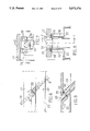
- FIGS. 1(a), (b) and (c) respectively show three successive stages in the construction of a bridge according to an embodiment of the present invention
- FIG. 2 is a front view of a tower used in such construction
- FIG. 3 is a side view of such tower
- FIG. 4 is a side view of a central portion of the tower on an enlarged scale with a truss mounted therein;
- FIG. 5 is a front view of the parts seen in FIG. 4;
- FIG. 6 is a detail view illustrating temporary anchoring of a cable to the truss
- FIG. 7 is a section on A--A of FIG. 6;
- FIG. 8 is a section on B--B of FIG. 6 or 7;
- FIG. 9 is a section on C--C of FIG. 7 or 8.
- FIGS. 1(a), (b) and (c) shows a series of towers 10a, 10b, 10c and 10d spaced apart and erected to extend across a body of water 11.
- Each tower as shown in FIGS. 2 and 3, consists of a footing 12 supporting a cylindrical pier 13 that projects above the water line to support a pier cap 14.
- Extending up from the pier cap 14 are four tower legs 15 to form a pylon.
- the legs 15 are parallel and define a space 16 between them, while in front view (FIG. 2) they firstly diverge from each other to a level at which a deck 17 is located, and then converge to meet at a pair of interconnected head members 18 to which the upper ends of cables 19 are secured in the usual manner.
- each tower receives an elongated truss 20 that is slidingly supported by at least two towers.
- the truss extends from tower 10a, through towers 10b and 10c.
- the truss has an air filled tank 21 that can be raised and lowered into the water.
- each of these tanks will preferably be fully submerged in order to provide a constant uplift force on the truss end.
- barges can be used to provide support for the truss. If the bridge is being built over land, other suitable supporting devices can be used instead of the tanks or barges.
- FIGS. 1(a) and (b) illustrate how the truss 20 is launched (using hydraulic jacks not shown) beyond the tower 10c to engage the tower 10d, which at this stage is only partly formed but already includes the pier cap 14 on which the truss end will rest.
- the truss 20 consists of the usual bottom and top chords 22, 23, side members 24 and top, bottom and intermediate cross struts 25.
- the right hand side of FIG. 4 and FIG. 5 show the truss 20 in its launching position in tower 10c.
- the left hand side of FIG. 4 shows the truss in an elevated (casting) position that will be described below.
- the bottom chords 22 carry teflon bearings 26 that slide on tracks 27 on the upper surface of the pier cap 14. These bearings move with the truss across the pier cap. Once the end of the pier cap is reached, the launching is stopped, the truss lifted (say by 10-20 mm) and the bearing is moved back to the first
- the tanks 21 are raised and the truss is moved further longitudinally and elevated (by 0.5 m to 1.0 m) to bring it into its casting position, as shown on the left hand side of FIG. 4 and in FIG. 1(c), by means of hydraulic jacks 28.
- the trailing portion 20a of the truss 20, i.e. the portion extending half way from tower 10b to tower 10c in FIG. 1(c) is less high than the remainder of the truss.
- the truss serves as a support for constructing a deck, e.g. as a support for formwork for making a concrete (or composite) deck 17 of the bridge superstructure, cantilevering half the span length on each side of the tower 10c.
- the deck is constructed at an elevation that is higher than the final deck elevation.
- the pouring level is shown at 17a, while the level of the deck portion formed previously is shown producing a deck portion 17.
- the stay cables 19 are installed and temporarily anchored to the top chords 23 of the truss 20 by means of a cable anchor 33 that engages a plate 34 that bears against a plate 35 embedded in the underside of the deck 17.
- the temporary anchoring to the truss is achieved by a bracket 36 welded at 37 to the upper flange of the top chord 23 and bolted at 38 to the plate 35 (FIGS. 6-9).
- the stay cables 19 close to the pylon may be slack when installed because of the elevated position of the formwork while in the casting position. Other cables 19 will have to be stressed to a certain level (less than the final stress) at this stage.
- the temporary anchoring of the cables is removed and the truss and the deck are lowered.
- the cable forces will be increased, and, upon reaching a certain level, the deck will be fully supported by the cables.
- the truss (and the forms it supports) is lowered further, the deck (now at level 17) will be freely suspended and the truss (and with it the forms) can be launched in the direction of the next span to be built, i.e. to repeat the process.
- the next tower e.g. tower 10d
- the next tower e.g. tower 10d
- Derrick cranes 30 moving on tracks on top of the truss will facilitate completion of the pylon, and may be assisted by floating cranes.
- the bottom forms may serve as access roads for trucks supplying the material (reinforcing bars and prestressing tendons, etc.) to the desired location.
- Casting of the deck will preferably start at the tower and progress symmetrically to both sides of the tower to create balanced conditions.
- the stay cables are installed from inside the truss.
- Cable drums 31 (FIG. 4) are lowered into the truss from the completed bridge and moved to the desired location inside the truss on tracks provided for this purpose.
- Numeral 32 shows a cat walk in the truss.
Landscapes
- Engineering & Computer Science (AREA)
- Architecture (AREA)
- Civil Engineering (AREA)
- Structural Engineering (AREA)
- Bridges Or Land Bridges (AREA)
Abstract
The invention relates to a method of constructing a cable-stayed bridge extending between at least three towers. Initially, a horizontally extending truss spanning from a first tower to a second tower is moved longitudinally to be projected from the second tower to a third tower. The truss is then elevated. A plurality of stay cables are then strung from an elevated location on the second tower to a series of temporary connections to the truss on both sides of the second tower. A deck portion is then constructed on the truss on both sides of the second tower, and the cables that are not connected to the truss are connected to this deck portion. Finally, the cables are disconnected from the truss and the truss and hence the deck portion are lowered, causing the cables to support the weight of the deck and to acquire the desired tensional stresses. The procedure is faster than hitherto know methods of constructing this type of bridge. The truss, which could be used to aid in the construction of any bridge over a body of water, has air filled tanks that can be moved vertically. This enables the tanks to be lowered and submerged in the body of water to provide upward supporting forces on the truss while it extends between the towers.
Description
This invention relates to the construction of bridges and more particularly cable-stayed bridges.
Conventionally, there are two methods of constructing cable-stayed bridges. One method involves sequentially casting short segments in place. The other method involves lifting short precast segments into place. Both methods require subsequent stressing of the cables to support each segment, and both methods are very time consuming.
An object of the present invention is to provide an improved method of constructing a cable-stayed bridge, and particularly a method that enables the bridge to be built much more rapidly than has been possible in the past.
To this end, the invention in its broad aspect provides a method of constructing a cable-stayed bridge, such method comprising the steps of erecting a truss on a tower, extending at least one stay cable (preferably all or nearly all the stay cables) from an elevated location on the tower to a temporary connection to the truss, constructing a deck on the truss and effecting a connection of the cable to this deck, and then disconnecting the cable from the truss and lowering the truss and hence the deck to tension the cable.
In a more specific form, the invention consists of a method of constructing a cable-stayed bridge extending between at least three towers, comprising the steps of causing a horizontally extending truss spanning from a first tower to a second tower to be moved longitudinally to be projected from the second tower to a third tower whereby to span between the latter towers while continuing to span between the first and second towers, elevating the truss relative to the second tower, extending a plurality of stay cables from an elevated location on the second tower to a series of temporary connections to the truss on both sides of the second tower, i.e. on the sides respectively extending towards the first and third towers, constructing a first deck portion extending along the truss on said sides of the second tower and effecting connections of the cables to this deck portion, and disconnecting the cables from the truss and lowering the truss and hence the deck portion relative to the second tower to cause the cables to support the weight of the deck portion and to acquire desired tensional stresses.
The construction of the bridge can be continued by causing the truss to be moved further longitudinally, i.e. to be projected from the third tower to a fourth tower whereby to span between the third and fourth towers while continuing to span between the second and third towers, again elevating the truss, and again extending a further plurality of stay cables from an elevated location on the third tower to a series of temporary connections to the truss on both sides of the third tower. A further deck portion is then constructed to extend along the truss on both sides of the third tower, and the further cables are connected to the further deck portion. The further cables are then disconnected from the truss and the truss is lowered again together with the further deck portion. This causes the further cables to support the weight of the further deck portion and to acquire desired tensional stresses, while aligning the further deck portion as a horizontal continuation of the first deck portion.
The invention also relates to a truss for use in one of the foregoing methods, or for use in the construction of bridges generally, not necessarily cable-stayed bridges.
In this aspect, the invention consists of a truss suitable for constructing a bridge over a body of water to extend between at least two towers, such truss having the purpose of providing a temporary support for the formation of a deck. The truss is fitted with air filled tanks and mechanisms for moving these tanks vertically relatively to the truss. This enables the tanks to be lowered and submerged in the body of water, which provides upward supporting forces on the truss while the truss is in position spanning the towers.
Specific examples of how the invention can be carried into practice are illustrated in the drawings and will now be described below.
FIGS. 1(a), (b) and (c) respectively show three successive stages in the construction of a bridge according to an embodiment of the present invention;
FIG. 2 is a front view of a tower used in such construction;
FIG. 3 is a side view of such tower;
FIG. 4 is a side view of a central portion of the tower on an enlarged scale with a truss mounted therein;
FIG. 5 is a front view of the parts seen in FIG. 4;
FIG. 6 is a detail view illustrating temporary anchoring of a cable to the truss;
FIG. 7 is a section on A--A of FIG. 6;
FIG. 8 is a section on B--B of FIG. 6 or 7; and
FIG. 9 is a section on C--C of FIG. 7 or 8.
FIGS. 1(a), (b) and (c) shows a series of towers 10a, 10b, 10c and 10d spaced apart and erected to extend across a body of water 11. Each tower, as shown in FIGS. 2 and 3, consists of a footing 12 supporting a cylindrical pier 13 that projects above the water line to support a pier cap 14. Extending up from the pier cap 14 are four tower legs 15 to form a pylon. In the side view (FIG. 3) the legs 15 are parallel and define a space 16 between them, while in front view (FIG. 2) they firstly diverge from each other to a level at which a deck 17 is located, and then converge to meet at a pair of interconnected head members 18 to which the upper ends of cables 19 are secured in the usual manner.
As seen in general terms in FIGS. 1(a), (b) and (c), and in more detail in FIGS. 4 and 5, the space 16 defined in each tower receives an elongated truss 20 that is slidingly supported by at least two towers. In FIG. 1(a) the truss extends from tower 10a, through towers 10b and 10c. At each end, the truss has an air filled tank 21 that can be raised and lowered into the water. When in use each of these tanks will preferably be fully submerged in order to provide a constant uplift force on the truss end. By fully submerging the tanks, the uplift forces remain constant, independent of water level, wave action or tidal changes. Alternatively, barges can be used to provide support for the truss. If the bridge is being built over land, other suitable supporting devices can be used instead of the tanks or barges.
FIGS. 1(a) and (b) illustrate how the truss 20 is launched (using hydraulic jacks not shown) beyond the tower 10c to engage the tower 10d, which at this stage is only partly formed but already includes the pier cap 14 on which the truss end will rest. The truss 20 consists of the usual bottom and top chords 22, 23, side members 24 and top, bottom and intermediate cross struts 25. The right hand side of FIG. 4 and FIG. 5 show the truss 20 in its launching position in tower 10c. The left hand side of FIG. 4 shows the truss in an elevated (casting) position that will be described below. The bottom chords 22 carry teflon bearings 26 that slide on tracks 27 on the upper surface of the pier cap 14. These bearings move with the truss across the pier cap. Once the end of the pier cap is reached, the launching is stopped, the truss lifted (say by 10-20 mm) and the bearing is moved back to the first end of the pier cap.
When the truss has reached the position shown in FIG. 1(b), the tanks 21 are raised and the truss is moved further longitudinally and elevated (by 0.5 m to 1.0 m) to bring it into its casting position, as shown on the left hand side of FIG. 4 and in FIG. 1(c), by means of hydraulic jacks 28. Note that the trailing portion 20a of the truss 20, i.e. the portion extending half way from tower 10b to tower 10c in FIG. 1(c) is less high than the remainder of the truss.
In this elevated condition the truss serves as a support for constructing a deck, e.g. as a support for formwork for making a concrete (or composite) deck 17 of the bridge superstructure, cantilevering half the span length on each side of the tower 10c. By virtue of the elevation of the truss, the deck is constructed at an elevation that is higher than the final deck elevation. In FIG. 1(c) the pouring level is shown at 17a, while the level of the deck portion formed previously is shown producing a deck portion 17. While the reinforcement and prestressing steel is placed on the forms to make the deck, the stay cables 19 are installed and temporarily anchored to the top chords 23 of the truss 20 by means of a cable anchor 33 that engages a plate 34 that bears against a plate 35 embedded in the underside of the deck 17. The temporary anchoring to the truss is achieved by a bracket 36 welded at 37 to the upper flange of the top chord 23 and bolted at 38 to the plate 35 (FIGS. 6-9). The stay cables 19 close to the pylon may be slack when installed because of the elevated position of the formwork while in the casting position. Other cables 19 will have to be stressed to a certain level (less than the final stress) at this stage. These cables will support the truss after their installation and will therefore reduce the forces on the truss generated by the weight of the deck concrete. During the pouring and hardening of the concrete deck, the installation of the stay cables will continue. After the concrete has reached sufficient strength the cables will be anchored directly to the concrete deck without intermediate anchorage to the top chord 23 of the steel truss 20, i.e. by releasing the bolts 38.
After the deck concrete has reached sufficient strength (say after 5 to 10 days) the temporary anchoring of the cables is removed and the truss and the deck are lowered. As the deck is lowered the cable forces will be increased, and, upon reaching a certain level, the deck will be fully supported by the cables. As the truss (and the forms it supports) is lowered further, the deck (now at level 17) will be freely suspended and the truss (and with it the forms) can be launched in the direction of the next span to be built, i.e. to repeat the process.
While the work on the deck is proceeding, the next tower, e.g. tower 10d, at the front end of the truss can be completed to become a pylon. Derrick cranes 30 moving on tracks on top of the truss will facilitate completion of the pylon, and may be assisted by floating cranes.
In the casting position, before pouring of the concrete, the bottom forms may serve as access roads for trucks supplying the material (reinforcing bars and prestressing tendons, etc.) to the desired location.
Casting of the deck will preferably start at the tower and progress symmetrically to both sides of the tower to create balanced conditions.
The stay cables are installed from inside the truss. Cable drums 31 (FIG. 4) are lowered into the truss from the completed bridge and moved to the desired location inside the truss on tracks provided for this purpose. Numeral 32 shows a cat walk in the truss.
Claims (13)
1. In a method of constructing a cable-stayed bridge the steps of
(a) erecting a truss on a tower,
(b) extending at least one stay cable from an elevated location on the tower to a temporary connection to the truss,
(c) constructing a deck on the truss and effecting a connection of the cable to the deck,
(d) disconnecting the cable from the truss, and
(e) lowering the truss and hence the deck to tension the cable.
2. A method according to claim 1, wherein the truss has one end portion of lesser height than the remainder of the truss.
3. A method of constructing a cable-stayed bridge extending between at least three towers, comprising
(a) locating a horizontally extending truss to extend from a first said tower, through a second said tower to a third said tower,
(b) extending a plurality of stay cables from an elevated location on the second tower to a series of temporary connections to the truss on the two sides of the second tower extending towards the first and third towers,
(c) constructing a deck extending along the truss on said two sides of the second tower, and connecting the cables to the deck,
(d) disconnecting the cables from the truss, and
(e) lowering the truss and hence the deck relative to the second tower to cause the cables to support the weight of the deck and to acquire desired tensional stresses.
4. A method according to claim 3, wherein the truss is of such a length as to span between said three towers.
5. A method according to claim 3, wherein the truss is mounted for longitudinal sliding through one said tower towards another said tower.
6. A method of constructing a cable-stayed bridge extending between at least three towers, comprising
(a) causing a horizontally extending truss spanning from a first said tower to a second said tower to be moved longitudinally to be projected from the second tower to a third said tower to span between the latter towers while continuing to span between the first and second towers,
(b) elevating the truss relative to the second tower,
(c) extending a plurality of stay cables from an elevated location on the second tower to a series of temporary connections to the truss on the two sides of the second tower respectively extending towards the first and third towers,
(d) constructing a first deck portion extending along the truss on said two sides of the second tower, and connecting the cables to the deck portion,
(e) disconnecting the cables from the truss, and
(f) lowering the truss and hence the deck portion relative to the second tower to cause the cables to support the weight of the deck portion and acquire desired tensional stresses.
7. A method according to claim 6, wherein construction of the deck portion takes place substantially symmetrical on said two sides of the second tower.
8. A method according to claim 6, including completing construction of the third tower while constructing the deck portion adjacent the second tower.
9. A method according to claim 6, including
(g) subsequently causing the truss to be moved further longitudinally to be projected from the third tower to a fourth said tower to span between the third and fourth towers while continuing to span between the second and third towers,
(h) elevating the truss,
(i) extending a further plurality of stay cables from an elevated location on the third tower to a series of temporary connections to the truss on the two sides of the third tower respectively extending towards the second and fourth towers,
(j) constructing a further portion of deck extending along the truss on said two sides of the third tower, and connecting said further cables to the further deck portion,
(k) disconnecting the further cables from the truss, and
(l) lowering the truss and hence the further deck portion to cause the further cables to support the weight of the further deck portion and acquire desired tensional stresses while aligning the further deck portion as a horizontal continuation of the first deck portion.
10. A method according to claim 3, wherein a trailing portion of the truss is of lesser height than the remaining portion of the truss to enable the truss to be elevated for construction of said further deck portion while remaining clear of the already constructed and lowered first deck portion.
11. A method according to claim 6, including providing support for cantilevered ends of the truss during longitudinal movement of the truss.
12. A method according to claim 11, wherein said support is provided by air filled tanks depending from the truss for submergence in a body of water over which the bridge is being constructed.
13. A method according to claim 12, wherein the tanks are located near the ends of the truss.
Applications Claiming Priority (2)
| Application Number | Priority Date | Filing Date | Title |
|---|---|---|---|
| CA000605489A CA1311094C (en) | 1989-07-12 | 1989-07-12 | Bridge construction |
| CA605489 | 1989-07-12 |
Publications (1)
| Publication Number | Publication Date |
|---|---|
| US5072474A true US5072474A (en) | 1991-12-17 |
Family
ID=4140337
Family Applications (1)
| Application Number | Title | Priority Date | Filing Date |
|---|---|---|---|
| US07/551,861 Expired - Fee Related US5072474A (en) | 1989-07-12 | 1990-07-12 | Bridge construction |
Country Status (2)
| Country | Link |
|---|---|
| US (1) | US5072474A (en) |
| CA (1) | CA1311094C (en) |
Cited By (24)
| Publication number | Priority date | Publication date | Assignee | Title |
|---|---|---|---|---|
| US5491861A (en) * | 1992-01-22 | 1996-02-20 | Penuela; Julio P. | Portable, demountable bridge of aerial point to ford rivers, chasms and the like |
| US5782738A (en) * | 1995-04-27 | 1998-07-21 | Bowers; John Murray | Method of construction of an annular elevated platform |
| US5896609A (en) * | 1997-11-21 | 1999-04-27 | Lin; Wei-Hwang | Safety method of construction a prestressed cable-stay bridge |
| US6189288B1 (en) * | 1998-05-22 | 2001-02-20 | John Murray Bowers | Method of construction of elevated annular platform |
| US6286271B1 (en) | 1999-05-26 | 2001-09-11 | Carl Cheung Tung Kong | Load-bearing structural member |
| US6412132B1 (en) * | 2000-08-02 | 2002-07-02 | Anton B. Majnaric | Methods for constructing a bridge utilizing in-situ forms supported by beams |
| US6721985B2 (en) * | 1999-04-09 | 2004-04-20 | Mccrary Homer T. | Intelligent public transit system using dual-mode vehicles |
| US20070006401A1 (en) * | 2005-07-09 | 2007-01-11 | James Thomson | Load bearing construction and method for installation |
| US20070119004A1 (en) * | 2005-11-29 | 2007-05-31 | Charles Fong | Longitudinally offset bridge substructure support system |
| US20070163058A1 (en) * | 2005-12-20 | 2007-07-19 | Flatiron Constructors, Inc. | Method and Apparatus for Bridge Construction |
| CN100535912C (en) * | 2008-02-28 | 2009-09-02 | 中铁大桥勘测设计院有限公司 | Method for determining stayd-cable bridge construction intermediate state utilizing unit original size |
| US8006339B1 (en) | 2009-03-27 | 2011-08-30 | Jeffery W Bennett | Prefabricated articulating pier cap |
| CN102373671A (en) * | 2011-11-18 | 2012-03-14 | 中铁四局集团有限公司 | Construction method of steel truss flexible arch bridge with vault push |
| CN102644241A (en) * | 2012-04-05 | 2012-08-22 | 广东省长大公路工程有限公司 | Space curved cable bent tower of cable-stayed bridge |
| CN105787183A (en) * | 2016-03-02 | 2016-07-20 | 东北林业大学 | Synthesis algorithm for determining reasonable finished-bridge cable force of cable-stayed bridge |
| JP2017089097A (en) * | 2015-11-02 | 2017-05-25 | 三井住友建設株式会社 | Construction method of main tower or bridge pier |
| CN106968160A (en) * | 2017-04-12 | 2017-07-21 | 中交第二公路勘察设计研究院有限公司 | A short-span cable-stayed bridge structure with steel truss girders and concrete girders |
| CN107476181A (en) * | 2017-08-30 | 2017-12-15 | 中铁大桥勘测设计院集团有限公司 | Cable-stayed bridge and its construction method are anchored outside a kind of combined purlin |
| CN108570937A (en) * | 2018-05-16 | 2018-09-25 | 贺宁 | A kind of push construction method that cable-stayed bridge main span is set up |
| CN108867383A (en) * | 2018-06-25 | 2018-11-23 | 中铁三局集团有限公司 | A kind of across the steel case trusses cable-stayed bridge rapid constructing method of double tower five |
| CN108951434A (en) * | 2018-10-10 | 2018-12-07 | 河北工业大学 | Curve lightweight I-beam beam bridge hauling construction cantilever end control device and control method |
| CN111533003A (en) * | 2020-06-09 | 2020-08-14 | 中铁十一局集团第一工程有限公司 | Cable installation lifting device for cable-stayed bridge |
| US20230102297A1 (en) * | 2021-09-29 | 2023-03-30 | Xi'an University Of Architecture And Technology | Construction method for overhead jacking of multi-track existing railway of frame bridge |
| CN119877417A (en) * | 2025-02-28 | 2025-04-25 | 中铁大桥局集团有限公司 | Cable-stayed bridge cantilever precast slab laying method and cable-stayed bridge structure |
Citations (11)
| Publication number | Priority date | Publication date | Assignee | Title |
|---|---|---|---|---|
| US2528089A (en) * | 1947-07-31 | 1950-10-31 | Merritt Chapman & Scott Corp | Submersible floating structure |
| US3145539A (en) * | 1959-10-23 | 1964-08-25 | Bethlehem Steel Corp | Offshore storage unit |
| FR1437689A (en) * | 1965-03-26 | 1966-05-06 | Entpr D Equipements Mecaniques | Improvements to floating equipment for drilling platforms |
| US3605669A (en) * | 1969-12-01 | 1971-09-20 | Kerr Mc Gee Chem Corp | Floating self-elevating platform |
| SU711225A1 (en) * | 1975-04-28 | 1980-01-25 | Государственный Проектный Институт Днепрпроектстальконструкция | Method of mounting flexible suspended systems |
| US4535498A (en) * | 1983-04-14 | 1985-08-20 | Webster David R | Suspension bridge |
| US4646379A (en) * | 1985-12-27 | 1987-03-03 | Figg And Muller Engineers, Inc. | Concrete deck truss bridge and method of construction |
| US4651375A (en) * | 1984-11-15 | 1987-03-24 | Romualdo Macchi | Launching system for bridge bays, especially continuous-beam bridges made up of prefabricated segments and to be tightened upon installation by means of prestressed wires |
| US4662019A (en) * | 1986-01-15 | 1987-05-05 | Figg And Muller Engineers, Inc. | Method of erecting a cable stayed bridge |
| US4799279A (en) * | 1985-12-02 | 1989-01-24 | Figg And Muller Engineers, Inc. | Method of constructing the approach and main spans of a cable stayed segmental bridge |
| US4987629A (en) * | 1988-03-25 | 1991-01-29 | Muller Jean M | Deck for wide-span bridge |
-
1989
- 1989-07-12 CA CA000605489A patent/CA1311094C/en not_active Expired
-
1990
- 1990-07-12 US US07/551,861 patent/US5072474A/en not_active Expired - Fee Related
Patent Citations (11)
| Publication number | Priority date | Publication date | Assignee | Title |
|---|---|---|---|---|
| US2528089A (en) * | 1947-07-31 | 1950-10-31 | Merritt Chapman & Scott Corp | Submersible floating structure |
| US3145539A (en) * | 1959-10-23 | 1964-08-25 | Bethlehem Steel Corp | Offshore storage unit |
| FR1437689A (en) * | 1965-03-26 | 1966-05-06 | Entpr D Equipements Mecaniques | Improvements to floating equipment for drilling platforms |
| US3605669A (en) * | 1969-12-01 | 1971-09-20 | Kerr Mc Gee Chem Corp | Floating self-elevating platform |
| SU711225A1 (en) * | 1975-04-28 | 1980-01-25 | Государственный Проектный Институт Днепрпроектстальконструкция | Method of mounting flexible suspended systems |
| US4535498A (en) * | 1983-04-14 | 1985-08-20 | Webster David R | Suspension bridge |
| US4651375A (en) * | 1984-11-15 | 1987-03-24 | Romualdo Macchi | Launching system for bridge bays, especially continuous-beam bridges made up of prefabricated segments and to be tightened upon installation by means of prestressed wires |
| US4799279A (en) * | 1985-12-02 | 1989-01-24 | Figg And Muller Engineers, Inc. | Method of constructing the approach and main spans of a cable stayed segmental bridge |
| US4646379A (en) * | 1985-12-27 | 1987-03-03 | Figg And Muller Engineers, Inc. | Concrete deck truss bridge and method of construction |
| US4662019A (en) * | 1986-01-15 | 1987-05-05 | Figg And Muller Engineers, Inc. | Method of erecting a cable stayed bridge |
| US4987629A (en) * | 1988-03-25 | 1991-01-29 | Muller Jean M | Deck for wide-span bridge |
Cited By (31)
| Publication number | Priority date | Publication date | Assignee | Title |
|---|---|---|---|---|
| US5491861A (en) * | 1992-01-22 | 1996-02-20 | Penuela; Julio P. | Portable, demountable bridge of aerial point to ford rivers, chasms and the like |
| US5782738A (en) * | 1995-04-27 | 1998-07-21 | Bowers; John Murray | Method of construction of an annular elevated platform |
| US5896609A (en) * | 1997-11-21 | 1999-04-27 | Lin; Wei-Hwang | Safety method of construction a prestressed cable-stay bridge |
| US6189288B1 (en) * | 1998-05-22 | 2001-02-20 | John Murray Bowers | Method of construction of elevated annular platform |
| US6721985B2 (en) * | 1999-04-09 | 2004-04-20 | Mccrary Homer T. | Intelligent public transit system using dual-mode vehicles |
| US6286271B1 (en) | 1999-05-26 | 2001-09-11 | Carl Cheung Tung Kong | Load-bearing structural member |
| US6412132B1 (en) * | 2000-08-02 | 2002-07-02 | Anton B. Majnaric | Methods for constructing a bridge utilizing in-situ forms supported by beams |
| US8347441B2 (en) * | 2005-07-09 | 2013-01-08 | James Thomson | Load bearing construction and method for installation |
| US20070006401A1 (en) * | 2005-07-09 | 2007-01-11 | James Thomson | Load bearing construction and method for installation |
| US20070119004A1 (en) * | 2005-11-29 | 2007-05-31 | Charles Fong | Longitudinally offset bridge substructure support system |
| US7478450B2 (en) * | 2005-11-29 | 2009-01-20 | Charles Fong | Longitudinally offset bridge substructure support system |
| US20070163058A1 (en) * | 2005-12-20 | 2007-07-19 | Flatiron Constructors, Inc. | Method and Apparatus for Bridge Construction |
| US7520014B2 (en) * | 2005-12-20 | 2009-04-21 | Flatiron Constructors, Inc. | Method and apparatus for bridge construction |
| CN100535912C (en) * | 2008-02-28 | 2009-09-02 | 中铁大桥勘测设计院有限公司 | Method for determining stayd-cable bridge construction intermediate state utilizing unit original size |
| US8006339B1 (en) | 2009-03-27 | 2011-08-30 | Jeffery W Bennett | Prefabricated articulating pier cap |
| CN102373671A (en) * | 2011-11-18 | 2012-03-14 | 中铁四局集团有限公司 | Construction method of steel truss flexible arch bridge with vault push |
| CN102373671B (en) * | 2011-11-18 | 2013-08-07 | 中铁四局集团有限公司 | Construction method of steel truss flexible arch bridge with vault push |
| CN102644241A (en) * | 2012-04-05 | 2012-08-22 | 广东省长大公路工程有限公司 | Space curved cable bent tower of cable-stayed bridge |
| CN102644241B (en) * | 2012-04-05 | 2014-07-30 | 广东省长大公路工程有限公司 | Space curved cable bent tower of cable-stayed bridge |
| JP2017089097A (en) * | 2015-11-02 | 2017-05-25 | 三井住友建設株式会社 | Construction method of main tower or bridge pier |
| CN105787183A (en) * | 2016-03-02 | 2016-07-20 | 东北林业大学 | Synthesis algorithm for determining reasonable finished-bridge cable force of cable-stayed bridge |
| CN106968160A (en) * | 2017-04-12 | 2017-07-21 | 中交第二公路勘察设计研究院有限公司 | A short-span cable-stayed bridge structure with steel truss girders and concrete girders |
| CN107476181A (en) * | 2017-08-30 | 2017-12-15 | 中铁大桥勘测设计院集团有限公司 | Cable-stayed bridge and its construction method are anchored outside a kind of combined purlin |
| CN108570937A (en) * | 2018-05-16 | 2018-09-25 | 贺宁 | A kind of push construction method that cable-stayed bridge main span is set up |
| CN108570937B (en) * | 2018-05-16 | 2019-08-20 | 湖南品智工程技术有限公司 | A kind of push construction method that cable-stayed bridge main span is set up |
| CN108867383A (en) * | 2018-06-25 | 2018-11-23 | 中铁三局集团有限公司 | A kind of across the steel case trusses cable-stayed bridge rapid constructing method of double tower five |
| CN108951434A (en) * | 2018-10-10 | 2018-12-07 | 河北工业大学 | Curve lightweight I-beam beam bridge hauling construction cantilever end control device and control method |
| CN108951434B (en) * | 2018-10-10 | 2024-01-30 | 河北工业大学 | Control device and control method for curved light I-shaped steel beam bridge dragging construction cantilever end |
| CN111533003A (en) * | 2020-06-09 | 2020-08-14 | 中铁十一局集团第一工程有限公司 | Cable installation lifting device for cable-stayed bridge |
| US20230102297A1 (en) * | 2021-09-29 | 2023-03-30 | Xi'an University Of Architecture And Technology | Construction method for overhead jacking of multi-track existing railway of frame bridge |
| CN119877417A (en) * | 2025-02-28 | 2025-04-25 | 中铁大桥局集团有限公司 | Cable-stayed bridge cantilever precast slab laying method and cable-stayed bridge structure |
Also Published As
| Publication number | Publication date |
|---|---|
| CA1311094C (en) | 1992-12-08 |
Similar Documents
| Publication | Publication Date | Title |
|---|---|---|
| US5072474A (en) | Bridge construction | |
| CN109235285B (en) | Cantilever pouring system and construction method for reinforced concrete arch bridge of large-span railway | |
| CN100543235C (en) | Method and system for erecting steel truss girder with cable-assisted full cantilever | |
| CN111622116A (en) | A construction method for asymmetric installation of a straddle-type light rail special steel box low tower cable-stayed bridge | |
| CN111794119B (en) | Temporary supporting system and hoisting method for basket type steel box tie bar arch | |
| CN110552296B (en) | Cable-stayed bridge dismantling construction method | |
| CN114457668B (en) | Large-span space special-shaped arch rib delphinium type basket steel box arch bridge and rapid construction method | |
| CN101424073A (en) | Bridge deck and steel girder second combination method for whole arch precasted steel-concrete composite continuous box girder | |
| CN113550230A (en) | A kind of prefabricated construction and control method of double-cable plane steel cable-stayed bridge with special-shaped arch tower | |
| US4403460A (en) | Method of erecting an elevated tank using formwork | |
| CN114016382B (en) | Prestressed floating bridge temporary bridge and construction method thereof | |
| US4646379A (en) | Concrete deck truss bridge and method of construction | |
| CN113802461B (en) | A steel box girder erection method | |
| US4767238A (en) | Method of accurately positioning a prefabricated structure on the sea bed or on a river bed by grounding, and a sea or a river construction obtained by said method | |
| CN110761165B (en) | Steel web box girder installation system and construction method thereof | |
| CN114960465B (en) | Swivel construction method for steel tower of chain lifting cable-stayed bridge | |
| EP0594151A1 (en) | Method and device for erecting long spanning girders, particularly on viaducts | |
| CN211340438U (en) | Push-pull system for steel bridges in navigable waters | |
| CN207727445U (en) | Steel Bailey bridge face loop wheel machine | |
| JPS6135325B2 (en) | ||
| CN117802918B (en) | A method for the overall demolition of a half-span cantilever beam of a cross-river concrete continuous beam bridge | |
| CN117306397B (en) | A method for constructing a long-span cable-stayed bridge across a deep canyon. | |
| CN117286805B (en) | An installation process for asymmetric steel-concrete composite beams under complex transportation conditions | |
| RU2270287C1 (en) | Through solid bridge span structure erection method (variants) | |
| MacAulay et al. | New cable stayed bridge rising out of Storstrømmen in Denmark |
Legal Events
| Date | Code | Title | Description |
|---|---|---|---|
| FEPP | Fee payment procedure |
Free format text: PAYOR NUMBER ASSIGNED (ORIGINAL EVENT CODE: ASPN); ENTITY STATUS OF PATENT OWNER: LARGE ENTITY |
|
| FPAY | Fee payment |
Year of fee payment: 4 |
|
| REMI | Maintenance fee reminder mailed | ||
| LAPS | Lapse for failure to pay maintenance fees | ||
| FP | Lapsed due to failure to pay maintenance fee |
Effective date: 19991217 |
|
| STCH | Information on status: patent discontinuation |
Free format text: PATENT EXPIRED DUE TO NONPAYMENT OF MAINTENANCE FEES UNDER 37 CFR 1.362 |