US505946A - Mechanical motor - Google Patents
Mechanical motor Download PDFInfo
- Publication number
- US505946A US505946A US505946DA US505946A US 505946 A US505946 A US 505946A US 505946D A US505946D A US 505946DA US 505946 A US505946 A US 505946A
- Authority
- US
- United States
- Prior art keywords
- shaft
- disks
- levers
- drive shaft
- drive
- Prior art date
- Legal status (The legal status is an assumption and is not a legal conclusion. Google has not performed a legal analysis and makes no representation as to the accuracy of the status listed.)
- Expired - Lifetime
Links
- 210000003414 extremity Anatomy 0.000 description 11
- 238000010276 construction Methods 0.000 description 3
- 210000001364 upper extremity Anatomy 0.000 description 2
- 238000007689 inspection Methods 0.000 description 1
- 230000001105 regulatory effect Effects 0.000 description 1
Images

Classifications
-
- F—MECHANICAL ENGINEERING; LIGHTING; HEATING; WEAPONS; BLASTING
- F16—ENGINEERING ELEMENTS AND UNITS; GENERAL MEASURES FOR PRODUCING AND MAINTAINING EFFECTIVE FUNCTIONING OF MACHINES OR INSTALLATIONS; THERMAL INSULATION IN GENERAL
- F16H—GEARING
- F16H31/00—Other gearings with freewheeling members or other intermittently driving members
- F16H31/003—Step-by-step mechanisms for rotary motion
- F16H31/005—Step-by-step mechanisms for rotary motion with pawls driven by a reciprocating or oscillating transmission member
-
- Y—GENERAL TAGGING OF NEW TECHNOLOGICAL DEVELOPMENTS; GENERAL TAGGING OF CROSS-SECTIONAL TECHNOLOGIES SPANNING OVER SEVERAL SECTIONS OF THE IPC; TECHNICAL SUBJECTS COVERED BY FORMER USPC CROSS-REFERENCE ART COLLECTIONS [XRACs] AND DIGESTS
- Y10—TECHNICAL SUBJECTS COVERED BY FORMER USPC
- Y10T—TECHNICAL SUBJECTS COVERED BY FORMER US CLASSIFICATION
- Y10T74/00—Machine element or mechanism
- Y10T74/15—Intermittent grip type mechanical movement
- Y10T74/1526—Oscillation or reciprocation to intermittent unidirectional motion
- Y10T74/1553—Lever actuator
- Y10T74/1555—Rotary driven element
Definitions
- This invention relates to mechanical motors; and it has for its object to provide an lmproved mechanical motor employed particularly for the propulsion of bicycles, other veh cles, boats, for operating toys and for all slm lar uses to which a mechanical propelling device could be employed.
- the main and primary object of the lnvention is to provide an improved mechanlcal motor or propelling device which 1s designed to be operated by weight and preferably the weight of a person, so that a powerful leverage will be secured as well as a very high rate of speed.
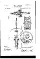
- FIG. 1 1s a side elevation of a safety bicycle having a propelling device'or mechanical motor applied thereto as contemplated by this inventron.
- Fig. 2 is a top plan view of the same.
- F1g. 1 s an enlarged detail sectional view on the hue a;0c of Fig. 2.
- Fig. 4 is an enlarged elevation of one of the friction clutches with the lnclosing face cap removed.
- Fig. 5 is an enlarged detail sectional view of the same, on the line 'yy of Fig; 4.
- A represents a safety bicycle of ordinary construction having the rear bearin g fork or rearwardly extending bearing arms B, in which is ournaled the drive shaft 0, on which shaft between the arms of the fork is loosely mounted the rear drive wheel D.
- the reardrive wheel D is provided at one side with a hub E, having the integral small sprocket wheel e, to which is connected the gearing for drlving the rear drive wheel in the manner now to be described.
- the opposite fixed clutch disks F provided at one side with the face pockets G, in which are arranged the movable clutch disks H, loosely attached to the shaft ends so as to work inside of the face pockets of the fixed clutch disk, andof a diameter less than the surrounding walls of the face pockets soas to leave a space between the periphery of the movable disk H, and the .walls of the said pockets of the fixed clutch disks.
- the opposite clutch springs I are the oppositely arranged in the face pockets of the fixed clutch disks, and above the movable disks H, therein.
- the clutch springs I are fixedly attached at one end as at i, to the periphery of movable disks H, at diametrically opposite portions thereof, and are provided with opposite bowed ends J,which are attached at their extremities at j, and j, to the extension arms X, attached to the lower ends of the swinging or oscillating operating levers or arms K.
- the swinging or oscillating operating levers K are arranged as illustrated in the drawings on both sides of the bicycle drive wheel D, and comprise light parallel'braced rods k, and carry the arms X, referred to, and which are provided with fulcrum boxes L, loosely fitting the opposite extremities of the drive shaft 0, alongside of the-movable clutch disks H, and serve to hold the same in position inside of the fixed clutch disks F.
- Gap plates M are secured to the outer faces of the movable disks H, so as to inclose the parts of the clutches, and hold the levers K, to their movement within the slots m, out in the flange of the disks F.
- the main drive sprocket wheel Q Fixedly secured to the drive shaft 0, alongside of one of the bearing arms and thedrive wheel D, is the main drive sprocket wheel Q, which is of a sufficient diameter to secure the proper gearing of the vehicle, in order to llavethe same attain any speed desired.
- sprocket wheel Q drives the main drive chain R, which leads therefromoverasmall sprocket wheel S.
- the small sprocket wheel S is,
- s is a speed sprocket wheel U, which is larger than the sprocket wheel S, though smaller;
- the turning drive shaft a-drive wheel loosely mounted on the shaft, friction clutches arranged on opposite extremities of the drive shaft and comprisi-ng fixed clutch disks turning with the shaft-,movable clutch disks loose on the shaft alongside of the fix ed disks, swinging 01' oscillating levers fu lcru m ed on the extremities of the shaft, and opposite clutch springs attached at one endto the periphery of the movable disks 'and at their other ends to said levers, being adapted to work against and grip the fixed clutch disk, and speed gearing leadingfrom the turning drive shaft to said drive wheel, substantially as set forth.
Landscapes
- Engineering & Computer Science (AREA)
- General Engineering & Computer Science (AREA)
- Mechanical Engineering (AREA)
- Toys (AREA)
Description
(,No Model.)
t e e. h S s t w S 2 R Om D0 M NL AM I N H m WM No. 505,946. Patented 001;. s, 1893.
Malay/zany,
(No Model.) 2 sheets-sheet W. C. LANGDON.
MECHANICAL MOTOR.
No. 505,946. Patented Oct. 3,1893.
, i a; l
"- EEE IMGIIIITITIL Igxhgir km W flaiydom a I r I o UNITE STATES ATENT Fries,
WILLIAM C. LANGDON, OF ERIE, ASSIGNOR OF ONE-HALF TO P. E. SHIPLER OF MERCER, PENNSYLVANIA.
MECHA NICAL MOTOR.
SPECIFICATION forming part of Letters Patent N 0. 505,946, dated October 3, 1893.
Application filed March 23, 1893.
To all whom it may concern.-
1 3e it known that I, WILLIAM G. LANGDON, a cltlzen of the United States, residing at Erie, 1n the county of Erie and State of Pennsylvanla, have inventeda new and useful Mechanical Motor, of which the following is a specification.
This invention relates to mechanical motors; and it has for its object to provide an lmproved mechanical motor employed particularly for the propulsion of bicycles, other veh cles, boats, for operating toys and for all slm lar uses to which a mechanical propelling device could be employed.
To this end the main and primary object of the lnvention is to provide an improved mechanlcal motor or propelling device which 1s designed to be operated by weight and preferably the weight of a person, so thata powerful leverage will be secured as well as a very high rate of speed. I
WIth these and many other objects in view which will readily appear as the nature of the lnventlon is better understood, the same conslsts 11113116 novel construction, combination and arrangement of parts hereinafter more fully described, illustrated and claimed. In the accompanying drawings:-Figure 1 1s a side elevation of a safety bicycle having a propelling device'or mechanical motor applied thereto as contemplated by this inventron. Fig. 2 is a top plan view of the same. F1g. 1s an enlarged detail sectional view on the hue a;0c of Fig. 2. Fig. 4 is an enlarged elevation of one of the friction clutches with the lnclosing face cap removed. Fig. 5 is an enlarged detail sectional view of the same, on the line 'yy of Fig; 4.
Referring to the accompanying drawings, A represents a safety bicycle of ordinary construction having the rear bearin g fork or rearwardly extending bearing arms B, in which is ournaled the drive shaft 0, on which shaft between the arms of the fork is loosely mounted the rear drive wheel D. The reardrive wheel D, is provided at one side with a hub E, having the integral small sprocket wheel e, to which is connected the gearing for drlving the rear drive wheel in the manner now to be described.
Fixedly attached to opposite ends of the Serial No. 467,330. (No model.)
drive shaft 0, outside of the bearing arms B,
are the opposite fixed clutch disks F, provided at one side with the face pockets G, in which are arranged the movable clutch disks H, loosely attached to the shaft ends so as to work inside of the face pockets of the fixed clutch disk, andof a diameter less than the surrounding walls of the face pockets soas to leave a space between the periphery of the movable disk H, and the .walls of the said pockets of the fixed clutch disks. Oppositely arranged in the face pockets of the fixed clutch disks, and above the movable disks H, therein are the oppositely arranged clutch springs I. The clutch springs I, are fixedly attached at one end as at i, to the periphery of movable disks H, at diametrically opposite portions thereof, and are provided with opposite bowed ends J,which are attached at their extremities at j, and j, to the extension arms X, attached to the lower ends of the swinging or oscillating operating levers or arms K.
The swinging or oscillating operating levers K, are arranged as illustrated in the drawings on both sides of the bicycle drive wheel D, and comprise light parallel'braced rods k, and carry the arms X, referred to, and which are provided with fulcrum boxes L, loosely fitting the opposite extremities of the drive shaft 0, alongside of the-movable clutch disks H, and serve to hold the same in position inside of the fixed clutch disks F. Gap plates M, are secured to the outer faces of the movable disks H, so as to inclose the parts of the clutches, and hold the levers K, to their movement within the slots m, out in the flange of the disks F.
The upper extremities of the swinging or oscillating levers K, have attached thereto an adjustable seat N, set forth in my separate application, filed March 21, 1893, and bearing Serial No. 467,054 and which of course is to be a weight in other applications of the motor, but which in the present case is designed to accommodate the rider whose feet are placed on suitable foot rests 0, attached to the frame of the machine between the two wheels, and in order to turn the drive shaft G, it is only necessary for the rider to allow himself to fall slightly with the upper extremities of the swinging levers, which are limited by suitably arranged stops P, andto rise again to secure a new grip for the clutch devices. It will be apparent by an inspection of the drawings, and particularly Fig. 4, that when the opposite levers K, lower, the bowed ends J, of the clutch springs I, are bulged or forced tightlyont against the inner peripheries-of the disks F, so as to secure a firm frictional grip, which is sufficient to turn the fixed clutch disks F, and the drive shaft to which they are attached. Now on the other hand when the operator relieves the upper ends of the levers I from his weight, the bowed ends of the springs, 1n assuming their normal positions, will throw the levers back to their farthest position, while at the same time releasing their'grip on the fixed clutch disks F. In toys andother similar objects after the upper ends of the operating levers have fallen, the same will of course have to be raised again manually to secure a new grip.
Fixedly secured to the drive shaft 0, alongside of one of the bearing arms and thedrive wheel D, is the main drive sprocket wheel Q, which is of a sufficient diameter to secure the proper gearing of the vehicle, in order to llavethe same attain any speed desired. The
sprocket wheel Q, drives the main drive chain R, which leads therefromoverasmall sprocket wheel S.
The small sprocket wheel S is,
mounted on one end of the counter shaft 3,; mounted in abearing 8, arranged on the rear extremities of the arm extensionsT, which are 1 extended rearwardly from the bearing arms B, to dispose the gearing back of the drive wheel,'-so as to not be in the way of ladies dresses, or with the feet of the rider. Fixedly secured to the opposite end of theshaft,
s, is a speed sprocket wheel U, which is larger than the sprocket wheel S, though smaller;
than the main drive sprocket wheel Q, and
is designed to communicate motion to the auxiliary drive chain V, which passes -therefrom over the drive wheel sprocket e, thereby I transmitting motion through a system of gearing from the drive shaft 0, to the drive wheel D, loosely mounted on such shaft. reason of the gearing from the drive shaft to Now by t the drive wheel, it. will be readily apparent that a very high rate of speed may be attained, and which of course can be regulated t it understood that changes in the form, proportion and the minor details of construction as embraced within the scope of the appended claims, may be resorted to without departing from the principle or sacrificing any of the advantages of this invention.
Having thus described my invention, what I claim, and desire to secure by Letters Patent, is-
1. In a device of the class described, the combination of a turning drive shaft, a drive wheel loosely mounted on said shaft, friction clutches arranged on opposite extremities of the drive shaft and each having alarge fixed disk and a smaller loose disk arranged inside of the fixed disk, opposite swinging levers fulcrumed on the drive shaft extremities, flat clutch springs attached at their extremities to the periphery of the smaller loose disks andto theswingin g levers, respectively,
and gearing leading from the turning drive shaft to the drive wheel loosely mounted thereon, substantially as set forth.
2. In adevice of the class described, the turning drive shaft, a-drive wheel loosely mounted on the shaft, friction clutches arranged on opposite extremities of the drive shaft and comprisi-ng fixed clutch disks turning with the shaft-,movable clutch disks loose on the shaft alongside of the fix ed disks, swinging 01' oscillating levers fu lcru m ed on the extremities of the shaft, and opposite clutch springs attached at one endto the periphery of the movable disks 'and at their other ends to said levers, being adapted to work against and grip the fixed clutch disk, and speed gearing leadingfrom the turning drive shaft to said drive wheel, substantially as set forth.
3. Inamechanical moteiythe turning drive shaft, a-drive wheel loosely mounted on said shaft, friction clutchesarranged on opposite extremities of the drive shaft and comprising fixed clutch disks turning with the sha'ft and provided atone side with face pockets, smaller movable clutch disks loose on the shaft and working inside of said face "pockets, swing-ing levers fulcrumed on the extremities of the shaft, clutch springs arranged in the face pockets of thefi-xed clutch disks and attached at one end to diametrically opposite portionsof the movableclutch disks, said springs being provided with bowed ends attached at their extremities to the swinging levers and contacting with thesu-rrounding walls ofsaid 'facepocketsand suitable gearingfrom the drive-shaft to the drive wheel, substantially as set forth.
In testimony that I claim the foregoing as my own I have hereto affixed my signature in the presence of two witnesses.
WILLIAM G. LANGDON.
Witnesses:
J. H. SIGGERS, BERNICEA. Woon.
Publications (1)
| Publication Number | Publication Date |
|---|---|
| US505946A true US505946A (en) | 1893-10-03 |
Family
ID=2574781
Family Applications (1)
| Application Number | Title | Priority Date | Filing Date |
|---|---|---|---|
| US505946D Expired - Lifetime US505946A (en) | Mechanical motor |
Country Status (1)
| Country | Link |
|---|---|
| US (1) | US505946A (en) |
-
0
- US US505946D patent/US505946A/en not_active Expired - Lifetime
Similar Documents
| Publication | Publication Date | Title |
|---|---|---|
| US505946A (en) | Mechanical motor | |
| US721943A (en) | Power-transmitting gearing. | |
| US619551A (en) | Changeable-speed gearing | |
| US504274A (en) | Propelling mechanism | |
| US875748A (en) | Vehicle propelling mechanism. | |
| US286702A (en) | Motor | |
| US1222398A (en) | Bicycle-frame. | |
| US248590A (en) | Moses b | |
| US339547A (en) | hammelmann | |
| US192623A (en) | Improvement in mechanical movements for operating blowers in forges | |
| US601440A (en) | Motor-vehicle | |
| US351733A (en) | bkidenthal | |
| US668769A (en) | Automobile. | |
| US521108A (en) | Power-transmitting mechanism | |
| US390662A (en) | Truman luthee goble | |
| US607075A (en) | Bicycle | |
| US561553A (en) | Extensible bicycle-crank | |
| US275144A (en) | Reciprocating mechanical movement | |
| US555271A (en) | Bicycle attachment | |
| US501874A (en) | Thirds to p | |
| US247723A (en) | Traction-engine | |
| US612257A (en) | Prank s | |
| US602283A (en) | clarke | |
| US769438A (en) | Automobile sleigh. | |
| US351118A (en) | mcmurray |