US5044952A - Device to prevent water stagnation in dental supply circuits - Google Patents
Device to prevent water stagnation in dental supply circuits Download PDFInfo
- Publication number
- US5044952A US5044952A US07/429,359 US42935989A US5044952A US 5044952 A US5044952 A US 5044952A US 42935989 A US42935989 A US 42935989A US 5044952 A US5044952 A US 5044952A
- Authority
- US
- United States
- Prior art keywords
- main
- valve
- bleed
- inlet line
- variable flow
- Prior art date
- Legal status (The legal status is an assumption and is not a legal conclusion. Google has not performed a legal analysis and makes no representation as to the accuracy of the status listed.)
- Expired - Lifetime
Links
Images

Classifications
-
- A—HUMAN NECESSITIES
- A61—MEDICAL OR VETERINARY SCIENCE; HYGIENE
- A61C—DENTISTRY; APPARATUS OR METHODS FOR ORAL OR DENTAL HYGIENE
- A61C1/00—Dental machines for boring or cutting ; General features of dental machines or apparatus, e.g. hand-piece design
- A61C1/0061—Air and water supply systems; Valves specially adapted therefor
- A61C1/0076—Sterilising operating fluids or fluid supply elements such as supply lines, filters
Definitions
- the present invention relates to a device designed to prevent the stagnation of water in the supply pipelines of medical equipment, and in particular, of dental surgery apparatus.
- a possible source of contamination threatening each power driven instrument connected to a conventional dental surgery apparatus is represented by the water used in operation of the apparatus.
- Stagnation it is known, has the effect of raising the overall quantity of micro-organisms in water, even drinking water, to levels that can no longer be considered safe.
- the microbiological content produced by stagnation poses no significant threat where drinking water is merely swallowed by a patient; in the particular instance of dental surgery, however, where water is supplied to surgical instruments and/or to power driven handpieces or other appliances associated with the apparatus, the micro-organisms generated by stagnation are inevitably brought into contact with exposed body tissue, with the result that infection can occur, occasioning prolonged healing time, inflammation, increased levels of pain post-treatment, and fever in more serious cases.
- Certain remedies involve dispensing a disinfectant continuously into the water supply circuits, though with the consequent drawbacks that the construction of the apparatus is rendered more complex, and the properties of the liquid are affected.
- the object of the invention is to provide a device that will prevent stagnation of water in the supply circuits of dental surgery apparatus, ultimately inhibiting the proliferation of micro-organisms, doing so without the use of additional substances; a further object of the invention is to enable a substantially instantaneous supply of warm water to those instruments which utilize feed and return flow in conjunction with a built-in on-off control, for example chip blowers.
- this expedient also affords the signal advantage that no chemical product whatsoever is mingled with the potable water supply; accordingly, the chemical and physical properties of the water remain unaffected, and there is no possibility of either patient or practitioner being invested by atomized disinfectant.
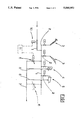
- FIG. 1 shows the schematic circuit diagram of a system according to the invention in a general form of application
- FIG. 2 is a diagram illustrating integration of the device disclosed into dental surgery apparatus.
- FIG. 1 which schematically illustrates a possible embodiment for the potable water supply circuit constituting part of a dental surgery apparatus
- 1 denotes a main inlet pipeline controlled by a main on-off valve 10, from which a number of branches 2 are taken off and routed to the handpieces of power driven instruments 3, to the replenishing outlet for an oral rinse drinking glass 4, and to a spittoon cup 5, the latter two connecting by way of respective waste pipes 8 with a main waste outlet 7 from the apparatus.
- the device according to the invention consists essentially in variable flow bleed-off means 6, embodied in practice as a valve connecting with the main inlet 1 on the one hand, and on the other, with the main waste outlet 7. More exactly, the valve 6 connects with the inlet 1 at a point downstream of the branch 2 to the last instrument 3 in line.
- valve 6 might be operated manually, or in a preferred embodiment, interlocked to the means by which the apparatus is switched on in such a way as to activate automatically.
- the flow passage of the valve 6 will be calibrated, clearly enough, in such a way that the steady bleed of water from the inlet line is kept small enough to contain consumption, and at the same time, to ensure that the supply to the instruments remains unaffected.
- the main inlet line 1 is controlled by a main valve 10 as in FIG. 1, and will be seen to divide into first and second circuits 1a and 1b; the first circuit 1a is connected initially to a first pressure reducing valve 20, downstream of which the water passes into a heater 21, then to the branches 2 supplying the handpieces 3 (each controlled by a relative on-off valve 2a), the chip blower 13 and the oral rinse outlet 4, whereas the second circuit 1b supplies the spittoon 5, by way of a second pressure reducing valve 20a.
- the chip blower 13 is of a general type provided with its own independent control, in the form of a button 13a and an on-off valve 13b incorporated into the handle.
- the oral rinse 4 and spittoon 5 stations are connected by respective waste lines 8 to the main waste outlet 7, and their relative water supply circuits controlled by conventional valves denoted 4a and 5a.
- variable flow restriction 6 (or bleed-off means, one for each blower 13 in the event of there being more than one fitted) located on a return line 18 departing from the blower 13, connected permanently to the relative supply branch 2, and discharging through the relative waste line 8 into the main waste outlet 7;
- valves 6 and 6a in question can be operated manually, or preferably, interlocked to the power switch of the apparatus and activated automatically.
- shut-off valve 6a differs from the restriction 6 inasmuch as the trickle can be halted completely in the event that the blower and the other handpieces are to be flooded with a liquid other than water, say, a physiological solution, which if allowed to drain continuously would be consumed too quickly.
- valves and restrictions of variable flow design could be replaced by others capable of performing the equivalent function, or in any event, of inducing and controlling a trickle of liquid from the pipelines in question.
- valve or restriction 6 (and 16) could be left permanently open, or operated intermittently; in either instance, the end remains one of ensuring a prolonged, stagnation-preventing bleed-off.
Landscapes
- Health & Medical Sciences (AREA)
- Engineering & Computer Science (AREA)
- Water Supply & Treatment (AREA)
- Oral & Maxillofacial Surgery (AREA)
- Dentistry (AREA)
- Epidemiology (AREA)
- Life Sciences & Earth Sciences (AREA)
- Animal Behavior & Ethology (AREA)
- General Health & Medical Sciences (AREA)
- Public Health (AREA)
- Veterinary Medicine (AREA)
- Dental Tools And Instruments Or Auxiliary Dental Instruments (AREA)
Abstract
The device consists in a variable restriction installed in conjunction with a chip blower, located between the warm water inlet and the return line connecting the relative handpiece to the main waste outlet, which is made to open continuously or intermittently, at least while the apparatus is in operation, so as to allow a moderate trickle of water through to the waste outlet and ensure that no stagnation occurs; the particular method of installing the restriction also permits of keeping the handpiece at a temperature near to that of the water supplied through the inlet, even when the blower is not actually in use.
Description
The present invention relates to a device designed to prevent the stagnation of water in the supply pipelines of medical equipment, and in particular, of dental surgery apparatus.
A possible source of contamination threatening each power driven instrument connected to a conventional dental surgery apparatus is represented by the water used in operation of the apparatus.
Whilst it is true that the domestic water supply, being potable, is not a carrier of micro-organisms in any significant quantity, it is equally true that there are conditions in which this same water is caused to linger and stagnate for considerable periods of time, both in the permanent pipework of the surgery's plumbing system and in the spray and replenishing circuits of the apparatus.
Stagnation, it is known, has the effect of raising the overall quantity of micro-organisms in water, even drinking water, to levels that can no longer be considered safe.
The microbiological content produced by stagnation poses no significant threat where drinking water is merely swallowed by a patient; in the particular instance of dental surgery, however, where water is supplied to surgical instruments and/or to power driven handpieces or other appliances associated with the apparatus, the micro-organisms generated by stagnation are inevitably brought into contact with exposed body tissue, with the result that infection can occur, occasioning prolonged healing time, inflammation, increased levels of pain post-treatment, and fever in more serious cases.
Certain remedies involve dispensing a disinfectant continuously into the water supply circuits, though with the consequent drawbacks that the construction of the apparatus is rendered more complex, and the properties of the liquid are affected.
The object of the invention is to provide a device that will prevent stagnation of water in the supply circuits of dental surgery apparatus, ultimately inhibiting the proliferation of micro-organisms, doing so without the use of additional substances; a further object of the invention is to enable a substantially instantaneous supply of warm water to those instruments which utilize feed and return flow in conjunction with a built-in on-off control, for example chip blowers.
The stated objects are fully realized according to the present invention, which consists essentially in installing a variable flow valve or restriction on the drinking water inlet to the replenishing and spray circuits of dental surgery apparatus, which by allowing a trickle of water through to the waste outlet is able to prevent stagnation.
Besides being extremely simple in construction and operation, this expedient also affords the signal advantage that no chemical product whatsoever is mingled with the potable water supply; accordingly, the chemical and physical properties of the water remain unaffected, and there is no possibility of either patient or practitioner being invested by atomized disinfectant.
The invention will now be described in detail, by way of example, with the aid of the accompanying drawings, in which:
FIG. 1 shows the schematic circuit diagram of a system according to the invention in a general form of application;
FIG. 2 is a diagram illustrating integration of the device disclosed into dental surgery apparatus.
With reference first to FIG. 1, which schematically illustrates a possible embodiment for the potable water supply circuit constituting part of a dental surgery apparatus, 1 denotes a main inlet pipeline controlled by a main on-off valve 10, from which a number of branches 2 are taken off and routed to the handpieces of power driven instruments 3, to the replenishing outlet for an oral rinse drinking glass 4, and to a spittoon cup 5, the latter two connecting by way of respective waste pipes 8 with a main waste outlet 7 from the apparatus.
In the example of FIG. 1, the device according to the invention consists essentially in variable flow bleed-off means 6, embodied in practice as a valve connecting with the main inlet 1 on the one hand, and on the other, with the main waste outlet 7. More exactly, the valve 6 connects with the inlet 1 at a point downstream of the branch 2 to the last instrument 3 in line.
Needless to say, the same result is obtainable with the point of connection between valve 6 and inlet 1 differently located, for example, downstream of the branch to the spittoon 5 (see phantom line, FIG. 1). The valve 6 might be operated manually, or in a preferred embodiment, interlocked to the means by which the apparatus is switched on in such a way as to activate automatically.
The flow passage of the valve 6 will be calibrated, clearly enough, in such a way that the steady bleed of water from the inlet line is kept small enough to contain consumption, and at the same time, to ensure that the supply to the instruments remains unaffected.
With reference to FIG. 2, which also illustrates a typical method of supplying potable water to a conventional apparatus, the main inlet line 1 is controlled by a main valve 10 as in FIG. 1, and will be seen to divide into first and second circuits 1a and 1b; the first circuit 1a is connected initially to a first pressure reducing valve 20, downstream of which the water passes into a heater 21, then to the branches 2 supplying the handpieces 3 (each controlled by a relative on-off valve 2a), the chip blower 13 and the oral rinse outlet 4, whereas the second circuit 1b supplies the spittoon 5, by way of a second pressure reducing valve 20a.
The chip blower 13 is of a general type provided with its own independent control, in the form of a button 13a and an on-off valve 13b incorporated into the handle. The oral rinse 4 and spittoon 5 stations are connected by respective waste lines 8 to the main waste outlet 7, and their relative water supply circuits controlled by conventional valves denoted 4a and 5a.
In the example of FIG. 2, the device according to the invention consists in:
a variable flow restriction 6 (or bleed-off means, one for each blower 13 in the event of there being more than one fitted) located on a return line 18 departing from the blower 13, connected permanently to the relative supply branch 2, and discharging through the relative waste line 8 into the main waste outlet 7; and
a valve 6a located immediately downstream of the restriction 6 and functioning as a shut-off.
Once again, the valves 6 and 6a in question can be operated manually, or preferably, interlocked to the power switch of the apparatus and activated automatically.
Adopting this expedient, it becomes possible to maintain a continuous trickle of running water along the entire length of the inlet line, and most especially, through the stretch branching off to the handpieces 3 and the rinse glass 4; whilst the flow generated will be limited, it is nonetheless sufficient to prevent stagnation occurring in the water lines and around the various valves, whether directly or indirectly invested. With the bleed-off means 6 installed on the return line 18 from the chip blower 13, it becomes possible, by virtue of the blower's mechanical embodiment, to maintain a steady flow of water through the blower handpiece: thus, not only is stagnation prevented, but the instrument 13 can be maintained at a temperature corresponding essentially to that generated by the heater 21, so that when activated, water will be ejected substantially at body temperature rather than cold; the closer the proximity of the on-off valve 13b and the entry to the return line 18, the more pronounced this effect will be.
In FIG. 2, the shut-off valve 6a differs from the restriction 6 inasmuch as the trickle can be halted completely in the event that the blower and the other handpieces are to be flooded with a liquid other than water, say, a physiological solution, which if allowed to drain continuously would be consumed too quickly.
Whilst the expedient thus described is certainly the most simple from the standpoint of economy in component parts, the alternative also exists of installing a second variable flow restriction 16, identical to the first 6, connected to the first circuit 1a (downstream of the heater 21) on the one hand, and on the other, to the main waste outlet 7. Given the simple conception of the device, use can be made of means, programmable on the part of the user and integrated into the control systems of the apparatus as a whole, designed to pilot a timer forming part of monitoring and control circuits 11 by which the main valve 10 and the trickle valve 6 (or valves 6 and 16) are caused to open at a set time prior to the commencement of surgery hours, and thus drain away the water that will have been stagnating during the `off` interval (nocturnal in particular).
Whilst reference is made in the foregoing text to valves and restrictions of variable flow design, such components could be replaced by others capable of performing the equivalent function, or in any event, of inducing and controlling a trickle of liquid from the pipelines in question. Similarly, the valve or restriction 6 (and 16) could be left permanently open, or operated intermittently; in either instance, the end remains one of ensuring a prolonged, stagnation-preventing bleed-off.
Claims (5)
1. A device serving to prevent stagnation of water in supply circuits of dental surgery apparatus having a potable water inlet line and a main waste outlet, comprising at least a variable flow bleed-off means connected between said potable water inlet line and said main waste outlet, said bleed-off means being opened continuously when the apparatus is in the operative phase to provide a constant and moderate trickle of water through to the main waste outlet, said potable water inlet line serving:
a first circuit having heating means to supply heated water to a branch handpiece line, to a chip blower of the type in continuous receipt of water from said inlet line, affording a handpiece built-in on-off valve and connected by way of a return line to said main waste outlet, and to an oral rinse glass replenishing outlet;
a second circuit supplying water at least to a spittoon cup;
wherein said bleed-off means is a variable flow restriction installed on the said chip blower return line in such a way as to bring a continuous connection between the relative supply inlet line and said main waste outlet and thus obtaining a heated running water flow through said blower handpiece;
a valve installed downstream of said variable flow restriction and serving to shut off the flow of water through the return line without altering the current setting of said restriction; and
wherein said bleed-off means comprise further a bleed-off valve installed on said branch handpiece line and consisting in a variable flow restriction the purpose of which is to bring a continuous connection between the branch handpieces line and the main waste outlet, in such a way as to ensure the constant and moderate trickle of water through to the main waste outlet.
2. A device as in claim 1, wherein said bleed-off means is a variable flow valve installed on the potable water inlet line.
3. A device as in claim 1, wherein said potable water inlet line serves a plurality of branches carrying potable water to handpieces, to an oral rinse glass replenishing outlet, and to a spittoon cup, said variable flow valve is installed on the potable water inlet line downstream of the branches serving the handpieces.
4. A device as in claim 1, associated with dental surgery apparatus in which the potable water inlet line is controlled by a main on-off valve, comprising means, embodied and operating independently of a main apparatus control system, able to monitor and control said variable flow bleed-off means and said main on-off valve.
5. A device as in claim 1, associated with dental surgery apparatus in which the potable water inlet line is controlled by a main on-off valve, comprising means, embodied and operating independently of a main apparatus control system, able to monitor and control said variable flow bleed-off means and said main on-off valve.
Applications Claiming Priority (4)
| Application Number | Priority Date | Filing Date | Title |
|---|---|---|---|
| IT3659A/88 | 1988-11-11 | ||
| IT8803659A IT1225498B (en) | 1988-11-11 | 1988-11-11 | Continuous flow device for dental instrument |
| IT8903398A IT1234042B (en) | 1989-03-24 | 1989-03-24 | Continuous flow device for dental instrument |
| IT3398A/89 | 1989-03-24 |
Publications (1)
| Publication Number | Publication Date |
|---|---|
| US5044952A true US5044952A (en) | 1991-09-03 |
Family
ID=26325371
Family Applications (1)
| Application Number | Title | Priority Date | Filing Date |
|---|---|---|---|
| US07/429,359 Expired - Lifetime US5044952A (en) | 1988-11-11 | 1989-10-31 | Device to prevent water stagnation in dental supply circuits |
Country Status (4)
| Country | Link |
|---|---|
| US (1) | US5044952A (en) |
| EP (1) | EP0368818B1 (en) |
| DE (1) | DE68917424T2 (en) |
| ES (1) | ES2057179T3 (en) |
Cited By (13)
| Publication number | Priority date | Publication date | Assignee | Title |
|---|---|---|---|---|
| US5295829A (en) * | 1991-07-24 | 1994-03-22 | Siemens Aktiengesellschaft | Water supply device for dental work stations |
| US5338194A (en) * | 1991-11-25 | 1994-08-16 | Kaltenbach & Voigt Gmbh & Co. | Medical treatment device and method for cleaning a flexible tube line |
| US5478236A (en) * | 1991-11-25 | 1995-12-26 | Annunzio; Frank | Solution dispensing dental system |
| US5593304A (en) * | 1995-06-16 | 1997-01-14 | Ram; Zeev | Dental apparatus including multiple-use electrically-oscillated handpiece |
| US5785523A (en) * | 1997-08-15 | 1998-07-28 | Overmyer; Thad J. | Dental water line flushing and disinfecting system |
| US6290498B1 (en) * | 1998-08-17 | 2001-09-18 | Claude Lachapelle | Water valve for dental handpiece |
| WO2002068336A1 (en) * | 2001-02-27 | 2002-09-06 | Peder Holmbom | An apparatus and a method for the disinfection of water for water consumption units designed for health or dental care purposes |
| US20030162144A1 (en) * | 2002-02-28 | 2003-08-28 | Castellini S.P.A. | Dental unit |
| US20050199535A1 (en) * | 2004-03-11 | 2005-09-15 | Stonecrest Innovations, Inc. | Dental waterline recirculator |
| US20060045795A1 (en) * | 2004-08-26 | 2006-03-02 | Fillery Edward D | Apparatus for sanitation of dental water lines |
| US20080299004A1 (en) * | 2005-08-24 | 2008-12-04 | Edward David Fillery | Method for sanitation of dental water lines |
| ITUA20162770A1 (en) * | 2016-04-21 | 2017-10-21 | Cefla Soc Cooperativa | ANTI-RESTAURANT SYSTEM FOR DENTAL MEETING |
| US20250099796A1 (en) * | 2014-11-05 | 2025-03-27 | Tabor Mountain, LLC | Remote monitoring and water shutoff systems |
Families Citing this family (5)
| Publication number | Priority date | Publication date | Assignee | Title |
|---|---|---|---|---|
| IT1282471B1 (en) * | 1995-03-27 | 1998-03-23 | Castellini Spa | TOTALLY HYGIENIC WATER - PNEUMATIC SYSTEM APPLICABLE ON DENTAL EQUIPMENT |
| JPH09122146A (en) * | 1995-11-02 | 1997-05-13 | Hinata Wada Seimitsu Seisakusho:Kk | Internal contamination prevention device for handpiece |
| IT1310262B1 (en) | 1999-02-16 | 2002-02-11 | Castellini Spa | FEEDING SYSTEM - HYGIENIZATION FOR WATER CIRCUITS JOINED DENTAL. |
| ES2250577T3 (en) * | 2002-12-23 | 2006-04-16 | Castellini S.P.A. | METHOD FOR STERILIZING / DISINFECTING THE WATER CIRCUIT OF A DENTAL EQUIPMENT AND DENTAL EQUIPMENT THAT PUTS INTO ACTION SUCH METHOD. |
| ITBO20030215A1 (en) * | 2003-04-11 | 2004-10-12 | Castellini Spa | HYDRAULIC CIRCUIT FOR DENTAL EQUIPMENT |
Citations (5)
| Publication number | Priority date | Publication date | Assignee | Title |
|---|---|---|---|---|
| US3035349A (en) * | 1960-12-09 | 1962-05-22 | Todd W Company | Dental drilling apparatus |
| US3169318A (en) * | 1960-06-20 | 1965-02-16 | Ritter Co Inc | Dental handpiece and apparatus for supplying heated fluid thereto |
| US3838516A (en) * | 1971-06-17 | 1974-10-01 | Nat Waterpure Corp | Water supply system for dental instruments |
| US4545956A (en) * | 1982-12-14 | 1985-10-08 | Siemens Aktiengesellschaft | Method and apparatus for disinfecting waterlines of a medical device |
| EP0313527A2 (en) * | 1987-10-22 | 1989-04-26 | CASTELLINI S.p.A. | A method for continuous sterilization of the waste pipelines of medical equipment or accessories, and a relative preparation |
-
1989
- 1989-10-31 US US07/429,359 patent/US5044952A/en not_active Expired - Lifetime
- 1989-11-10 EP EP89830490A patent/EP0368818B1/en not_active Expired - Lifetime
- 1989-11-10 ES ES89830490T patent/ES2057179T3/en not_active Expired - Lifetime
- 1989-11-10 DE DE68917424T patent/DE68917424T2/en not_active Expired - Fee Related
Patent Citations (5)
| Publication number | Priority date | Publication date | Assignee | Title |
|---|---|---|---|---|
| US3169318A (en) * | 1960-06-20 | 1965-02-16 | Ritter Co Inc | Dental handpiece and apparatus for supplying heated fluid thereto |
| US3035349A (en) * | 1960-12-09 | 1962-05-22 | Todd W Company | Dental drilling apparatus |
| US3838516A (en) * | 1971-06-17 | 1974-10-01 | Nat Waterpure Corp | Water supply system for dental instruments |
| US4545956A (en) * | 1982-12-14 | 1985-10-08 | Siemens Aktiengesellschaft | Method and apparatus for disinfecting waterlines of a medical device |
| EP0313527A2 (en) * | 1987-10-22 | 1989-04-26 | CASTELLINI S.p.A. | A method for continuous sterilization of the waste pipelines of medical equipment or accessories, and a relative preparation |
Cited By (18)
| Publication number | Priority date | Publication date | Assignee | Title |
|---|---|---|---|---|
| US5295829A (en) * | 1991-07-24 | 1994-03-22 | Siemens Aktiengesellschaft | Water supply device for dental work stations |
| US5338194A (en) * | 1991-11-25 | 1994-08-16 | Kaltenbach & Voigt Gmbh & Co. | Medical treatment device and method for cleaning a flexible tube line |
| US5478236A (en) * | 1991-11-25 | 1995-12-26 | Annunzio; Frank | Solution dispensing dental system |
| US5593304A (en) * | 1995-06-16 | 1997-01-14 | Ram; Zeev | Dental apparatus including multiple-use electrically-oscillated handpiece |
| US5785523A (en) * | 1997-08-15 | 1998-07-28 | Overmyer; Thad J. | Dental water line flushing and disinfecting system |
| US6290498B1 (en) * | 1998-08-17 | 2001-09-18 | Claude Lachapelle | Water valve for dental handpiece |
| US20040074832A1 (en) * | 2001-02-27 | 2004-04-22 | Peder Holmbom | Apparatus and a method for the disinfection of water for water consumption units designed for health or dental care purposes |
| WO2002068336A1 (en) * | 2001-02-27 | 2002-09-06 | Peder Holmbom | An apparatus and a method for the disinfection of water for water consumption units designed for health or dental care purposes |
| US20030162144A1 (en) * | 2002-02-28 | 2003-08-28 | Castellini S.P.A. | Dental unit |
| US20050199535A1 (en) * | 2004-03-11 | 2005-09-15 | Stonecrest Innovations, Inc. | Dental waterline recirculator |
| US20060045795A1 (en) * | 2004-08-26 | 2006-03-02 | Fillery Edward D | Apparatus for sanitation of dental water lines |
| US20080299004A1 (en) * | 2005-08-24 | 2008-12-04 | Edward David Fillery | Method for sanitation of dental water lines |
| US7645420B2 (en) * | 2005-08-24 | 2010-01-12 | Edward David Fillery | Method for sanitation of dental water lines |
| US20250099796A1 (en) * | 2014-11-05 | 2025-03-27 | Tabor Mountain, LLC | Remote monitoring and water shutoff systems |
| US12440714B2 (en) * | 2014-11-05 | 2025-10-14 | Tabor Mountain, LLC | Remote monitoring and water shutoff systems |
| ITUA20162770A1 (en) * | 2016-04-21 | 2017-10-21 | Cefla Soc Cooperativa | ANTI-RESTAURANT SYSTEM FOR DENTAL MEETING |
| EP3235464A1 (en) | 2016-04-21 | 2017-10-25 | Cefla Societa' Cooperativa | Anti-stagnation device for a dental treatment unit |
| RU2718609C2 (en) * | 2016-04-21 | 2020-04-08 | Чефла Сочета Кооператива | Decontamination device for a dental unit |
Also Published As
| Publication number | Publication date |
|---|---|
| DE68917424D1 (en) | 1994-09-15 |
| EP0368818A2 (en) | 1990-05-16 |
| DE68917424T2 (en) | 1994-12-15 |
| EP0368818B1 (en) | 1994-08-10 |
| ES2057179T3 (en) | 1994-10-16 |
| EP0368818A3 (en) | 1990-12-27 |
Similar Documents
| Publication | Publication Date | Title |
|---|---|---|
| US5044952A (en) | Device to prevent water stagnation in dental supply circuits | |
| JPH02124156A (en) | Dental treatment device | |
| EP0734692B1 (en) | A total hygiene water-pneumatic system applicable on dental apparatus | |
| JP2003169815A (en) | Medical and dental examination equipment | |
| CN100368310C (en) | Sterilizer device for water pipeline | |
| EP1161959B1 (en) | Method for sterilising conduits that convey fluids to dental instruments, and dental unit | |
| EP3235464B1 (en) | Anti-stagnation device for a dental treatment unit | |
| JPH10338952A (en) | Germless water supply device | |
| EP1332725B1 (en) | An apparatus for supplying and heating fluids in dental units | |
| US7211220B2 (en) | Method for cleaning /disinfecting /sterilizing the water circuits of dental units and a dental unit implementing the method | |
| KR20190051419A (en) | The disinfection and sterilization method of water pipe of dental treatment equipments and the device | |
| US20030162144A1 (en) | Dental unit | |
| KR101580505B1 (en) | Water supply for dental unit Chair | |
| EP1029512A2 (en) | A feeding and sanitizing system for dental unit water circuits | |
| KR20040032068A (en) | An auxiliary unit for the sanitising treatment of dental equipment | |
| EP1433434B1 (en) | A method for sterilising/disinfecting the water circuit of a dental unit and a dental unit implementing the method | |
| US20040191721A1 (en) | Method for sterilizing the water circuits of dental apparatus and apparatus implementing the method | |
| US20040184951A1 (en) | Method for sanitizing the water circuits of dental units and a dental unit implementing the method | |
| KR20240087333A (en) | Dental hot water supplying apparatus | |
| WO2002068336A1 (en) | An apparatus and a method for the disinfection of water for water consumption units designed for health or dental care purposes | |
| TW200610518A (en) | A real-time heating system for the washing liquid used on an endoscopic surgery |
Legal Events
| Date | Code | Title | Description |
|---|---|---|---|
| AS | Assignment |
Owner name: CASTELLINI S.P.A., ITALY Free format text: ASSIGNMENT OF ASSIGNORS INTEREST.;ASSIGNOR:CASTELLINI, FRANCO;REEL/FRAME:005170/0250 Effective date: 19891025 |
|
| STCF | Information on status: patent grant |
Free format text: PATENTED CASE |
|
| FEPP | Fee payment procedure |
Free format text: PAYOR NUMBER ASSIGNED (ORIGINAL EVENT CODE: ASPN); ENTITY STATUS OF PATENT OWNER: SMALL ENTITY |
|
| FPAY | Fee payment |
Year of fee payment: 4 |
|
| FPAY | Fee payment |
Year of fee payment: 8 |
|
| FPAY | Fee payment |
Year of fee payment: 12 |