US504344A - Thermal cut-out - Google Patents
Thermal cut-out Download PDFInfo
- Publication number
- US504344A US504344A US504344DA US504344A US 504344 A US504344 A US 504344A US 504344D A US504344D A US 504344DA US 504344 A US504344 A US 504344A
- Authority
- US
- United States
- Prior art keywords
- springs
- paper
- thermal cut
- block
- thermal
- Prior art date
- Legal status (The legal status is an assumption and is not a legal conclusion. Google has not performed a legal analysis and makes no representation as to the accuracy of the status listed.)
- Expired - Lifetime
Links
- 239000004020 conductor Substances 0.000 description 2
- 239000004744 fabric Substances 0.000 description 2
- 230000001012 protector Effects 0.000 description 2
- 241001654412 Corchorus hirsutus Species 0.000 description 1
- 235000007261 jackswitch Nutrition 0.000 description 1
- 238000000034 method Methods 0.000 description 1
- 239000002023 wood Substances 0.000 description 1
Images
Classifications
-
- H—ELECTRICITY
- H01—ELECTRIC ELEMENTS
- H01H—ELECTRIC SWITCHES; RELAYS; SELECTORS; EMERGENCY PROTECTIVE DEVICES
- H01H37/00—Thermally-actuated switches
- H01H37/02—Details
- H01H37/04—Bases; Housings; Mountings
Definitions
- My invention relates to lightning arresters or strong current protectors.
- tapes of conducting paper supported upon a wooden base have been largely used in tele, phone exchange circuits to protect the instruments from strong currents, as lightning, No satisfactory method of supporting the paper had been devised prior to my invention herein, which would permit of the renewal of the paper, instantaneously and without the trouble and inconvenience of manipulating adjusting screws.
- My invention consists of two springs included in an electric circuit and preferably placed parallel, in combination with a stick or support, notched so as to be held by the springs, when placed between them, and a tape or strip of gilded paper or other conducting fabric supported upon the stick and held in place by the pressure of the springs.
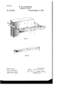
- FIG. 1 is a perspective View illustrative of my invention.
- Fig. 2 is a perspective view of the stick which forms the support for the paper.
- the springs ct, b are of the form now largely used in spring jack switches.
- the line in may be conveniently attached to 4o the rear end of one spring and the line out to the rear end of the other spring.
- the standard c may be of wood and long enough to support say one hundred pairs of springs.
- the conducting tape d may consist of gilt 45 paper or of other suitable fusible fabric.y This strip of paper is placed over the rear side of stick or block e and the block is then forced between the springs. The tape is thus pressed against the notch f, by spring a, and 5o against notch g by spring b. The paper may be readily removed by simply pulling the block e away from the springs.
- AIt is herehy'oertitled that in llettes'Patent No. 504155544,l granted ,'eSepte-niber 5, 1893, upon the application of William M. bvroodridge, of Highland Park, Illinois, for an improvement in Thermal Out-Outs, the'dateof lingthe application was erroneously printed November 19, 1837,77 whereas said date should have been printed November 19, 1887, that the same may conform to the record of the ease in the Patent Office.
Landscapes
- Time Recorders, Dirve Recorders, Access Control (AREA)
Description
(No Model.)
'y W- M. GOODRIDGE.
THERMAL GUT-OUT.
No. 504,344. Y Patented sept. 5, 1893.v
`and electric light currents.
UNITED STATES PATENT OFFICE.
VILLIAM M. GOODRIDGE, OF HIGHLAND PARK, ASSIGNOR TO THE VESTERN ELECTRIC COMPANY, OF CHICAGO, ILLINOIS.
THERMAL CUT-OUT.
SPECIFICATION forming part of Letters Patent No. 4,344, dated September 5, 1893. Application filed November 19, 1837. Serial No. 255,604. (No model.)
To all whom it may concern:
Be it known that I, WILLIAM M. GOOD- RIDGE, a citizen of the United States, residing at Highland Park, in the county of Lake and State of Illinois, have invented a certain new and useful Improvement in Strong-Current Protectors, (Case No. 5,) of which the following is a full, clear, concise, and exact description, reference being had to the accompanying drawings, forming a part of this specification.
My invention relates to lightning arresters or strong current protectors. Heretofore tapes of conducting paper supported upon a wooden base have been largely used in tele, phone exchange circuits to protect the instruments from strong currents, as lightning, No satisfactory method of supporting the paper had been devised prior to my invention herein, which would permit of the renewal of the paper, instantaneously and without the trouble and inconvenience of manipulating adjusting screws.
My invention consists of two springs included in an electric circuit and preferably placed parallel, in combination with a stick or support, notched so as to be held by the springs, when placed between them, and a tape or strip of gilded paper or other conducting fabric supported upon the stick and held in place by the pressure of the springs.
My invention is illustrated in the accompanying drawings, in which- Figure 1 is a perspective View illustrative of my invention. Fig. 2 is a perspective view of the stick which forms the support for the paper.
The springs ct, b, it will be Seen, are of the form now largely used in spring jack switches. The line in may be conveniently attached to 4o the rear end of one spring and the line out to the rear end of the other spring. The standard c may be of wood and long enough to support say one hundred pairs of springs.
The conducting tape d may consist of gilt 45 paper or of other suitable fusible fabric.y This strip of paper is placed over the rear side of stick or block e and the block is then forced between the springs. The tape is thus pressed against the notch f, by spring a, and 5o against notch g by spring b. The paper may be readily removed by simply pulling the block e away from the springs.
Having thus described my invention, I claim as new and desire to secure by Letters Patentl. The combination with parallel springs, of the notched block and a strip of conducting material held against the block by the pressure of the springs, as described.
2. The combination with springs included in an electric circuit of a strip of conducting material in contact with said springs and held by the tension of said springs, against a block or support inserted between the springs, as described.
In witness whereof I hereunto subscribe my name this 16th day of June, A. D. 1887.
WILLIAM M. eooDEIDeE.
Witnesses:
GEORGE P. BARTON, WM. M. GILLER.
Correction in Letters Patent No. 504,344.
It is hereby certied that in Letters Patent No. 504,344, granted September 5, 17893,
upon the application of William M. Uroodridge, of Highland Park, Illinois, for an improvement in Thermal Out-Outs]7 the date of filing the application was erroneously printed November 19, 1837, whereas said date should have been printed November and that the said Letters Patent should be read with this correction therein the record of the case in the Patent Oce. day of September, A.' D. 1893.
JNO. M. REYNOLDS, n Assistant Secretary of the Interior.
that the same may conform to Signed, countersigned, and sealed this 19th [SEAL] lountersigned S. T. FISHER,
Acting Commissioner of vlcrtents.y
AIt is herehy'oertitled that in llettes'Patent No. 504155544,l granted ,'eSepte-niber 5, 1893, upon the application of William M. bvroodridge, of Highland Park, Illinois, for an improvement in Thermal Out-Outs, the'dateof lingthe application was erroneously printed November 19, 1837,77 whereas said date should have been printed November 19, 1887, that the same may conform to the record of the ease in the Patent Office.
i this 19th day of September, AiD. 1893.
JNO. M'. REYNOLDS, Assistant Secretary of the Interior.
Signed, conntersigned, and sealed [SEAL] Acting Commissioner of Paterits.
and thatvthe said Letters Patent should be read with this eorrectiontherein
Publications (1)
| Publication Number | Publication Date |
|---|---|
| US504344A true US504344A (en) | 1893-09-05 |
Family
ID=2573180
Family Applications (1)
| Application Number | Title | Priority Date | Filing Date |
|---|---|---|---|
| US504344D Expired - Lifetime US504344A (en) | Thermal cut-out |
Country Status (1)
| Country | Link |
|---|---|
| US (1) | US504344A (en) |
-
0
- US US504344D patent/US504344A/en not_active Expired - Lifetime
Similar Documents
| Publication | Publication Date | Title |
|---|---|---|
| US802736A (en) | Electric fuse. | |
| US688554A (en) | Circuit making and breaking device. | |
| US752613A (en) | A corpoeation | |
| US622748A (en) | Rheostat | |
| US1011896A (en) | Fuse. | |
| US449289A (en) | Fuse for electric circuits | |
| US969818A (en) | Telephone-drop. | |
| US717201A (en) | Cut-out. | |
| US716649A (en) | Circuit-breaker. | |
| US1277133A (en) | Protective device. | |
| US407454A (en) | Lightning-arrester | |
| US761675A (en) | Electric cut-out. | |
| US937326A (en) | Fuse-mounting for electric cut-outs. | |
| US803881A (en) | Self-soldering thermal protector. | |
| US679897A (en) | Self-restoring fuse-block. | |
| US977140A (en) | Electric switch. | |
| US903813A (en) | Contactless thermal protector. | |
| US774160A (en) | Self-soldering thermal protector. | |
| US842738A (en) | Fuse-mount. | |
| US1110259A (en) | Electric-line-apparatus protector. | |
| US802497A (en) | Ground-strip for protective apparatus. | |
| US851051A (en) | Heat-coil. | |
| US576040A (en) | Of same place | |
| US724507A (en) | Electrical protector. | |
| US303627A (en) | Daniel deawbaugh |