US5042244A - Roof top chain - Google Patents
Roof top chain Download PDFInfo
- Publication number
- US5042244A US5042244A US07/610,074 US61007490A US5042244A US 5042244 A US5042244 A US 5042244A US 61007490 A US61007490 A US 61007490A US 5042244 A US5042244 A US 5042244A
- Authority
- US
- United States
- Prior art keywords
- chain
- legs
- plates
- link
- flanges
- Prior art date
- Legal status (The legal status is an assumption and is not a legal conclusion. Google has not performed a legal analysis and makes no representation as to the accuracy of the status listed.)
- Expired - Fee Related
Links
Images


Classifications
-
- F—MECHANICAL ENGINEERING; LIGHTING; HEATING; WEAPONS; BLASTING
- F16—ENGINEERING ELEMENTS AND UNITS; GENERAL MEASURES FOR PRODUCING AND MAINTAINING EFFECTIVE FUNCTIONING OF MACHINES OR INSTALLATIONS; THERMAL INSULATION IN GENERAL
- F16G—BELTS, CABLES, OR ROPES, PREDOMINANTLY USED FOR DRIVING PURPOSES; CHAINS; FITTINGS PREDOMINANTLY USED THEREFOR
- F16G13/00—Chains
- F16G13/02—Driving-chains
- F16G13/06—Driving-chains with links connected by parallel driving-pins with or without rollers so-called open links
-
- B—PERFORMING OPERATIONS; TRANSPORTING
- B65—CONVEYING; PACKING; STORING; HANDLING THIN OR FILAMENTARY MATERIAL
- B65G—TRANSPORT OR STORAGE DEVICES, e.g. CONVEYORS FOR LOADING OR TIPPING, SHOP CONVEYOR SYSTEMS OR PNEUMATIC TUBE CONVEYORS
- B65G17/00—Conveyors having an endless traction element, e.g. a chain, transmitting movement to a continuous or substantially-continuous load-carrying surface or to a series of individual load-carriers; Endless-chain conveyors in which the chains form the load-carrying surface
- B65G17/30—Details; Auxiliary devices
- B65G17/38—Chains or like traction elements; Connections between traction elements and load-carriers
- B65G17/42—Attaching load carriers to traction elements
-
- B—PERFORMING OPERATIONS; TRANSPORTING
- B65—CONVEYING; PACKING; STORING; HANDLING THIN OR FILAMENTARY MATERIAL
- B65G—TRANSPORT OR STORAGE DEVICES, e.g. CONVEYORS FOR LOADING OR TIPPING, SHOP CONVEYOR SYSTEMS OR PNEUMATIC TUBE CONVEYORS
- B65G21/00—Supporting or protective framework or housings for endless load-carriers or traction elements of belt or chain conveyors
- B65G21/20—Means incorporated in, or attached to, framework or housings for guiding load-carriers, traction elements or loads supported on moving surfaces
-
- F—MECHANICAL ENGINEERING; LIGHTING; HEATING; WEAPONS; BLASTING
- F16—ENGINEERING ELEMENTS AND UNITS; GENERAL MEASURES FOR PRODUCING AND MAINTAINING EFFECTIVE FUNCTIONING OF MACHINES OR INSTALLATIONS; THERMAL INSULATION IN GENERAL
- F16G—BELTS, CABLES, OR ROPES, PREDOMINANTLY USED FOR DRIVING PURPOSES; CHAINS; FITTINGS PREDOMINANTLY USED THEREFOR
- F16G13/00—Chains
- F16G13/18—Chains having special overall characteristics
-
- B—PERFORMING OPERATIONS; TRANSPORTING
- B65—CONVEYING; PACKING; STORING; HANDLING THIN OR FILAMENTARY MATERIAL
- B65G—TRANSPORT OR STORAGE DEVICES, e.g. CONVEYORS FOR LOADING OR TIPPING, SHOP CONVEYOR SYSTEMS OR PNEUMATIC TUBE CONVEYORS
- B65G2201/00—Indexing codes relating to handling devices, e.g. conveyors, characterised by the type of product or load being conveyed or handled
- B65G2201/02—Articles
Definitions
- the present invention relates to capped transfer or roller chain of the type used for transporting items such as lumber from point to point.
- Capped roller chain generally comprise a standard type roller chain wherein an overlay (referred to as a cap or "roof top”) spans the top of the two side bars or plates forming each link of the chain.
- an overlay referred to as a cap or "roof top”
- two or more lengths of such chain extend in spaced parallel relation and are driven at the same speed. Items to be transported are placed transversely across the chain lengths and are carried thereby.
- the roof top or cap has been formed by an upper extension of one of the side bars of each link.
- metal caps have been welded to the side plates of the links.
- Metal caps have the drawback of scratching or otherwise marring the surface of items being loaded thereon for transport. More recently, ultra high molecular weight polyethylene roof top caps have been provided to overcome the aforementioned problem. Such plastic caps include a steel clamp which is used in welding the caps to the side bars of the chain links.
- the chain In order to support the loads carried by the chain, the chain typically runs atop a metal support plate or channel. More recently, in order to reduce noise, plastic chain support channels have been introduced to eliminate the metal to metal contact between chain and support.
- a snap fit attachable cap for roller chain the side plates of which are modified to facilitate the snap fit connection.
- the cap comprises a unitary body of non-abrasive high strength material having an upper body portion which transversely spans the two side plates of each link.
- a pair of leg portions depend from the upper body portion and are spaced apart a distance to straddle the side plates (i.e., receive the side plates therebetween).
- Each of the leg portions includes a button portion formed therealong. Recepticals for the buttons are provided in the side plates of each link to provide a snap fit connection between link and cap.
- the legs of the cap extend below the side plates of each link to provide a smooth, low friction load carrying area for the chain to ride on.
- the cap of the present invention can be made of high density polyethylene, a material which exhibits the desired low-friction, non abrasive characteristics while being extremely tough and yet sufficiently flexible to permit the legs to outwardly flex when affixing and removing the cap.
- FIG. 1 is a top view of a length of single pitch conveyor roller chain incorporating the roof top cap of the present invention
- FIG. 2 is a side elevation of the roof top chain of FIG. 1;
- FIG. 3 is a sectional view taken, as indicated, along the line 3--3 of FIG. 2;
- FIG. 4 is a sectional view taken, as indicated, along the line 4--4 of FIG. 2;
- FIG. 5 is a perspective view of the roof top cap
- FIG. 6 is a top view of the roof top cap
- FIG. 7 is a side elevational view of the roof top cap
- FIG. 8 is an end elevation view of the roof top cap
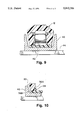
- FIG. 9 is a sectional view similar to FIG. 4 but showing the channel guide in relation to the roof top chain.
- FIG. 10 is a fragmentary view showing a cap leg bottom portion in a fully worn condition.
- a length of single pitch conveyor roller chain 10 is shown in combination with a plurality of roof top caps 12.
- the chain includes alternating pin links 14 and roller links 16.
- the links of chain 10 are of conventional design of the smaller roller type per ANSI standard (see ASME/ANSI B29.4M-1986) and, more particularly, chain known as 81X.
- the pin links 14 each include a pair of identical parallel side plates 14A, 14B; the roller links 16 including a pair of identical parallel side plates 16A, 16B.
- the side plates 16A, 16B of the roller links 16 each have circular apertures near the two opposed ends thereof to receive bushings 18 which carry rollers 20.
- the side plates 14A, 14B of the pin links 14 also each have apertures near the two opposed ends thereof through which pins 22 extend. As is standard, pins 22 extend through the bushings 18 of the roller links.
- each of the side plates of the pin links 14 and the roller links 16 include an additional aperture midway between the opposed ends thereof to serve as snap fit female receptical for the caps 12.
- These additional apertures are shown in dotted outline in FIG. 2 as apertures 26 (in the case of the roller link side plates 16) and aperture 24 (pin link side plates 14), and are best shown in FIGS. 3 and 4.
- apertures 24 and 26 are identical in size to the apertures formed in the roller links 16 for receiving bushings 18.
- the roof top caps 12 each comprises a unitary body of nonabrasive, low friction, high strength material, preferably high density polyethylene ("HDPE").
- the unitary body of each cap 12 includes an upper body portion 28 and a pair of downwardly depending leg portions 30, 32.
- the upper body portion 28 of the cap body has a transverse dimension at least sufficient to span both the side plates of the pin links and roller links.
- the opposed depending leg portions 30, 32 of the cap body are spaced apart a distance to accommodate the side plates therebetween.
- the spacing between the legs 30, 32 of a cap 12 is of necessity dependent upon whether the cap 12 is to be affixed to a pin link 14 or a roller link 16.
- each of the depending legs 30, 32 has on its inner face a bulge or button portion 30A, 32A to fit within apertures 24, 26 of the side plates 14A, 14B of the pin links 14 and side plates 16A, 16B of the roller links 16.
- the upper body portion 28 of each cap 12 includes an underside surface 34 having side regions 34A, 34B to seat upon the top edges of the side plates of a pin or roller link (as best shown in FIGS. 3, 4 and 8).
- the side regions 34A, 34B flank a central underside region 34C which is raised relative thereto so as to accommodate the teeth of chain driving sprockets (not shown).
- the caps 12 preferrably are formed of HDPE, a material exhibiting low surface friction but which is extremely tough.
- HDPE a material exhibiting low surface friction but which is extremely tough.
- notches 36 are formed at or near the junction of the leg portions 30, 32 and upper body portion 28.
- HDPE possesses a combination of characteristics (i.e., moldability, strength and elasticity) more desireable than other polymers, such as ultra high molecular weight polyethylene, polypropylene and low density polyethylene.
- the legs 30, 32 must outwardly flex or deflect when affixing the caps to the links and when removing same.
- the other polymer materials noted exhibited either excessive stiffness or insufficient stiffness.
- Caps 12 are easily connected to links 14, 16 merely by pushing the caps 12 downwardly onto the links.
- the legs 30, 32 deflect outwardly as the buttons 30A, 30B engage the outer surfaces of the side plates.
- the buttons then, when properly oriented relative to apertures 24, 26 are caused to snap into the apertures due to the inherent resiliency of the HDPE material.
- the bottom portions of the buttons 30A, 32A are appropriately cammed or beveled, as shown.
- the legs 30, 32 extend below the bottom edges of the side plates of the links (as best shown in FIGS. 2, 3 and 4) and terminate in flat bottom surfaces 38A, 38B. Such bottom surfaces rest upon a horizontal chain support surface or track above which the roller chain 10 extends.
- the low friction characteristic of the HDPE allows for reduced drag and noisy metal to metal contact is thereby eliminated.
- the roof top chain of the present invention has particular application in the transport of lumber.
- the lumber is loaded onto parallel lengths of chain from one side thereof in a direction transverse to the direction of chain travel.
- sidewise (or lateral) forces are applied to the chain during the loading operation.
- each of the chain lengths is supported by a channel shaped guide such as is shown in FIG. 9 as guide 40.
- a channel shaped guide such as is shown in FIG. 9 as guide 40.
- a strip of plastic such as strip 42 in FIG. 9, is placed between the channel and the chain to reduce sound and reduce friction.
- the channel itself is formed of plastic.
- the bottom edges of the chain side plates cut indentations into the web of the channel guide 40 (or into the plastic strip 42 if present). Such indentations typically are not straight line, but rather tend to curve irregularly along the direction of chain travel. At times the chain tracks along such indentations in wobbly fashion and at times the chain jumps out of the tracks. Either case is detrimental to chain life and increases drag.
- the chain illustrated herein is known in the industry as 81X chain, the dimensions of which are well known, the side plate height being 1.125 inches, the side plate thickness being 0.155 inch, the pitch being 2.609 inches, the greatest width dimension (pin head to opposite pin head) being 1 15/16 inches.
- the channel 40 illustrated in FIG. 9 has an exterior width of 3.0 inches, an interior width at the web base of approximately 2.38 inches and an interior width at the top of the flanges of approximately 2.75 inches.
- the cap 12 has an exterior width at the base of the legs of approximately 2.135 inches and 2.5 inches at the top of the legs so that, when the cap is centered within the channel as shown in FIG. 9, there is a clearance or gap between each of the legs of the cap and the corresponding channel flange of approximately 0.125 inch.
- the legs of caps 12 substantially fill the gap between the flanges of the channel guide and the chain thereby eliminating the above noted problems previously encountered during the loading operation.
- the width of the bottom surface of the legs of the cap is greater than the side plate thickness (0.155 inch) of 81X chain, the leg bottom surface width for caps affixed to pin links being 0.187 inch and for caps affixed to roller links being 0.375 inch.
- This increased width aids in the distribution of vertical load forces.
- Such coupled with the less abrasive characteristic of the polymer material (as compared to the steel side plates), substantially eliminates groove cutting problems noted above.
- the effective width of the bottom surfaces of the legs increases by the thickness of the side plates.
Landscapes
- Engineering & Computer Science (AREA)
- General Engineering & Computer Science (AREA)
- Mechanical Engineering (AREA)
- Chain Conveyers (AREA)
Abstract
Description
Claims (2)
Priority Applications (1)
| Application Number | Priority Date | Filing Date | Title |
|---|---|---|---|
| US07/610,074 US5042244A (en) | 1990-05-21 | 1990-11-07 | Roof top chain |
Applications Claiming Priority (2)
| Application Number | Priority Date | Filing Date | Title |
|---|---|---|---|
| US52585290A | 1990-05-21 | 1990-05-21 | |
| US07/610,074 US5042244A (en) | 1990-05-21 | 1990-11-07 | Roof top chain |
Related Parent Applications (1)
| Application Number | Title | Priority Date | Filing Date |
|---|---|---|---|
| US52585290A Continuation | 1990-05-21 | 1990-05-21 |
Publications (1)
| Publication Number | Publication Date |
|---|---|
| US5042244A true US5042244A (en) | 1991-08-27 |
Family
ID=27061922
Family Applications (1)
| Application Number | Title | Priority Date | Filing Date |
|---|---|---|---|
| US07/610,074 Expired - Fee Related US5042244A (en) | 1990-05-21 | 1990-11-07 | Roof top chain |
Country Status (1)
| Country | Link |
|---|---|
| US (1) | US5042244A (en) |
Cited By (28)
| Publication number | Priority date | Publication date | Assignee | Title |
|---|---|---|---|---|
| EP0693639A1 (en) * | 1994-07-21 | 1996-01-24 | REXNORD KETTE GmbH & Co. KG | Chain |
| EP0703163A1 (en) * | 1991-07-03 | 1996-03-27 | Western Atlas Inc. | Conveyor drive chains |
| US6471041B1 (en) | 2000-03-31 | 2002-10-29 | Kimberly-Clark Worldwide, Inc. | Roller chain attachment member |
| USD469940S1 (en) | 2000-12-01 | 2003-02-04 | White Conveyors, Inc. | Multiple holding device |
| USD469939S1 (en) | 2000-12-01 | 2003-02-04 | White Conveyors, Inc. | Single holding device |
| US6662545B1 (en) * | 2002-11-05 | 2003-12-16 | Masakazu Yamamoto | Chain cover |
| US20040185978A1 (en) * | 2001-02-14 | 2004-09-23 | Prince Jeffrey Theorin | Chain with selectively engaged links |
| US20050167250A1 (en) * | 2004-02-02 | 2005-08-04 | Schumacher Jeffrey A. | Anti-shingling product conveying chain |
| US6952916B1 (en) * | 1998-06-18 | 2005-10-11 | Assa Abloy Financial Services Ab | Multi-link connector |
| US20060096243A1 (en) * | 2004-11-05 | 2006-05-11 | Weaver J M | Case packer with a segmented drivable riding strip and segmented drivable riding strip therefore |
| US20060254886A1 (en) * | 2005-04-29 | 2006-11-16 | Cash John W Iii | Stablized guided conveyor belt with multiple base chains and interchangeable conveyor plates |
| US20070187213A1 (en) * | 2006-02-10 | 2007-08-16 | Carlo Garbagnati | Metal chain link for chain conveyor with perfected structure |
| US20070221479A1 (en) * | 2004-04-05 | 2007-09-27 | Alexander Schmezer | Compression-Resistant Drive Chain for an Actuating Device |
| US20070227861A1 (en) * | 2006-04-04 | 2007-10-04 | Rexnord Industries, Llc | Conveyor module with a snap fit extension for supporting a roller |
| US20080010964A1 (en) * | 2006-07-14 | 2008-01-17 | Eric Wettlaufer | Chain link overlay and method of improving chain link aesthetics |
| US20090133375A1 (en) * | 2007-11-26 | 2009-05-28 | Daniel Wu | Chain with Protection Device |
| US20090260291A1 (en) * | 2008-04-18 | 2009-10-22 | Automatic Technology (Australia) Pty. Ltd. | Noise Reduction Device |
| US20110226593A1 (en) * | 2010-03-22 | 2011-09-22 | Ramsey Products Corporation | Nested end link and multi-link conveyor chain |
| US8474607B2 (en) | 2010-11-19 | 2013-07-02 | Ramsey Products Corporation | Integrated multi-functional links for chain link conveyor and method |
| US8756907B2 (en) * | 2011-08-30 | 2014-06-24 | Esco Corporation | Chain and coupling links |
| AU2008201482B2 (en) * | 2008-04-01 | 2015-10-08 | Automatic Technology (Australia) Pty Ltd | Noise reduction device |
| EP3106599A1 (en) * | 2015-06-17 | 2016-12-21 | Hörmann KG Antriebstechnik | Building closure drive device |
| US9945083B2 (en) * | 2015-06-18 | 2018-04-17 | Hefei University Of Technology | Unidirectional bend drive chain and lift mechanism and boom barrier including same |
| US20180195581A1 (en) * | 2015-07-29 | 2018-07-12 | Tsubakimoto Chain Co. | Chain bending limiting attachment |
| US10358293B2 (en) | 2017-01-11 | 2019-07-23 | Pennine Industrial Equipment Limited | Conveyor chain |
| US11332315B2 (en) * | 2018-09-21 | 2022-05-17 | Rexnord Flattop Europe S.R.L. | Link for a chain for an article conveyor |
| US11465852B2 (en) | 2018-09-07 | 2022-10-11 | Cambridge International, Inc. | Modular top flatwire conveyor belt systems and methods |
| US20240010435A1 (en) * | 2021-03-19 | 2024-01-11 | Schenck Process Europe Gmbh | Chain link, plate-link chain and chain conveyor |
Citations (8)
| Publication number | Priority date | Publication date | Assignee | Title |
|---|---|---|---|---|
| GB731361A (en) * | 1952-05-19 | 1955-06-08 | Renold Chains Ltd | Improvements relating to endless chain conveyors |
| US2954113A (en) * | 1957-01-09 | 1960-09-27 | Chain Belt Co | Conveyer chain attachments |
| US2955700A (en) * | 1957-03-21 | 1960-10-11 | Diamond Chain Company Inc | Conveyor chain |
| US3842968A (en) * | 1973-11-19 | 1974-10-22 | Velten & Pulver | Snap-on attachment |
| US3910406A (en) * | 1973-09-26 | 1975-10-07 | Velten & Pulver | Two-part clip |
| US3944059A (en) * | 1974-09-20 | 1976-03-16 | Garvey Corporation | Endless chain conveyor link |
| US4096943A (en) * | 1975-11-28 | 1978-06-27 | Rexnord Inc. | Snap-on top plate assembly |
| US4301915A (en) * | 1980-01-11 | 1981-11-24 | Rexnord Inc. | Snap-on attachment for roller chain conveyors |
-
1990
- 1990-11-07 US US07/610,074 patent/US5042244A/en not_active Expired - Fee Related
Patent Citations (8)
| Publication number | Priority date | Publication date | Assignee | Title |
|---|---|---|---|---|
| GB731361A (en) * | 1952-05-19 | 1955-06-08 | Renold Chains Ltd | Improvements relating to endless chain conveyors |
| US2954113A (en) * | 1957-01-09 | 1960-09-27 | Chain Belt Co | Conveyer chain attachments |
| US2955700A (en) * | 1957-03-21 | 1960-10-11 | Diamond Chain Company Inc | Conveyor chain |
| US3910406A (en) * | 1973-09-26 | 1975-10-07 | Velten & Pulver | Two-part clip |
| US3842968A (en) * | 1973-11-19 | 1974-10-22 | Velten & Pulver | Snap-on attachment |
| US3944059A (en) * | 1974-09-20 | 1976-03-16 | Garvey Corporation | Endless chain conveyor link |
| US4096943A (en) * | 1975-11-28 | 1978-06-27 | Rexnord Inc. | Snap-on top plate assembly |
| US4301915A (en) * | 1980-01-11 | 1981-11-24 | Rexnord Inc. | Snap-on attachment for roller chain conveyors |
Cited By (40)
| Publication number | Priority date | Publication date | Assignee | Title |
|---|---|---|---|---|
| EP0703163A1 (en) * | 1991-07-03 | 1996-03-27 | Western Atlas Inc. | Conveyor drive chains |
| US5582287A (en) * | 1991-07-03 | 1996-12-10 | Western Atlas, Inc. | Drive chain for accumulation conveyor |
| EP0693639A1 (en) * | 1994-07-21 | 1996-01-24 | REXNORD KETTE GmbH & Co. KG | Chain |
| US6952916B1 (en) * | 1998-06-18 | 2005-10-11 | Assa Abloy Financial Services Ab | Multi-link connector |
| US6471041B1 (en) | 2000-03-31 | 2002-10-29 | Kimberly-Clark Worldwide, Inc. | Roller chain attachment member |
| USD469939S1 (en) | 2000-12-01 | 2003-02-04 | White Conveyors, Inc. | Single holding device |
| USD469940S1 (en) | 2000-12-01 | 2003-02-04 | White Conveyors, Inc. | Multiple holding device |
| US20040185978A1 (en) * | 2001-02-14 | 2004-09-23 | Prince Jeffrey Theorin | Chain with selectively engaged links |
| US6662545B1 (en) * | 2002-11-05 | 2003-12-16 | Masakazu Yamamoto | Chain cover |
| US20050167250A1 (en) * | 2004-02-02 | 2005-08-04 | Schumacher Jeffrey A. | Anti-shingling product conveying chain |
| US6945388B2 (en) | 2004-02-02 | 2005-09-20 | Rexnord Industries, Inc. | Anti-shingling product conveying chain |
| US20070221479A1 (en) * | 2004-04-05 | 2007-09-27 | Alexander Schmezer | Compression-Resistant Drive Chain for an Actuating Device |
| US20060096243A1 (en) * | 2004-11-05 | 2006-05-11 | Weaver J M | Case packer with a segmented drivable riding strip and segmented drivable riding strip therefore |
| US20060254886A1 (en) * | 2005-04-29 | 2006-11-16 | Cash John W Iii | Stablized guided conveyor belt with multiple base chains and interchangeable conveyor plates |
| US7407052B2 (en) * | 2005-04-29 | 2008-08-05 | Mead Westvaco Packaging Systems, Llc | Stabilized guided conveyor belt with multiple base chains and interchangeable conveyor plates |
| US20070187213A1 (en) * | 2006-02-10 | 2007-08-16 | Carlo Garbagnati | Metal chain link for chain conveyor with perfected structure |
| US20070227861A1 (en) * | 2006-04-04 | 2007-10-04 | Rexnord Industries, Llc | Conveyor module with a snap fit extension for supporting a roller |
| US7527146B2 (en) * | 2006-04-04 | 2009-05-05 | Rexnord Industries, Llc | Conveyor module with a snap fit extension for supporting a roller |
| KR101414595B1 (en) | 2006-04-04 | 2014-08-07 | 렉스노드 인더스트리즈, 엘엘씨 | A conveyor module with a snap fit extension for supporting rollers |
| US20080010964A1 (en) * | 2006-07-14 | 2008-01-17 | Eric Wettlaufer | Chain link overlay and method of improving chain link aesthetics |
| US7571595B2 (en) * | 2006-07-14 | 2009-08-11 | Eric Wettlaufer | Chain link overlay and method of improving chain link aesthetics |
| US7546726B1 (en) * | 2007-11-26 | 2009-06-16 | Kmc Chain Industrial Co., Ltd. | Chain with protection device |
| US20090133375A1 (en) * | 2007-11-26 | 2009-05-28 | Daniel Wu | Chain with Protection Device |
| AU2008201482B2 (en) * | 2008-04-01 | 2015-10-08 | Automatic Technology (Australia) Pty Ltd | Noise reduction device |
| US20090260291A1 (en) * | 2008-04-18 | 2009-10-22 | Automatic Technology (Australia) Pty. Ltd. | Noise Reduction Device |
| US9243685B2 (en) * | 2008-04-18 | 2016-01-26 | Automatic Technology (Australia) Pty. Ltd. | Noise reduction device |
| EP2368816B1 (en) | 2010-03-22 | 2016-12-07 | Ramsey Products Corporation | Link for a conveyor chain and multi-link conveyor chain with such links |
| US20110226593A1 (en) * | 2010-03-22 | 2011-09-22 | Ramsey Products Corporation | Nested end link and multi-link conveyor chain |
| US8322522B2 (en) | 2010-03-22 | 2012-12-04 | Ramsey Products Corporation | Nested end link and multi-link conveyor chain |
| US8474607B2 (en) | 2010-11-19 | 2013-07-02 | Ramsey Products Corporation | Integrated multi-functional links for chain link conveyor and method |
| US8756907B2 (en) * | 2011-08-30 | 2014-06-24 | Esco Corporation | Chain and coupling links |
| EP3106599A1 (en) * | 2015-06-17 | 2016-12-21 | Hörmann KG Antriebstechnik | Building closure drive device |
| US9945083B2 (en) * | 2015-06-18 | 2018-04-17 | Hefei University Of Technology | Unidirectional bend drive chain and lift mechanism and boom barrier including same |
| US20180195581A1 (en) * | 2015-07-29 | 2018-07-12 | Tsubakimoto Chain Co. | Chain bending limiting attachment |
| US10718407B2 (en) * | 2015-07-29 | 2020-07-21 | Tsubakimoto Chain Co. | Chain bending limiting attachment |
| US10358293B2 (en) | 2017-01-11 | 2019-07-23 | Pennine Industrial Equipment Limited | Conveyor chain |
| US11465852B2 (en) | 2018-09-07 | 2022-10-11 | Cambridge International, Inc. | Modular top flatwire conveyor belt systems and methods |
| US11332315B2 (en) * | 2018-09-21 | 2022-05-17 | Rexnord Flattop Europe S.R.L. | Link for a chain for an article conveyor |
| US20240010435A1 (en) * | 2021-03-19 | 2024-01-11 | Schenck Process Europe Gmbh | Chain link, plate-link chain and chain conveyor |
| US12448216B2 (en) * | 2021-03-19 | 2025-10-21 | Qlar Europe Gmbh | Chain link, plate-link chain and chain conveyor |
Similar Documents
| Publication | Publication Date | Title |
|---|---|---|
| US5042244A (en) | Roof top chain | |
| US6601697B2 (en) | Sloped surface conveyor belt | |
| US6216854B1 (en) | Side-flexing conveyor belt | |
| US5314059A (en) | Conveyor frame for chain conveyor | |
| US3669247A (en) | Conveyor system and attachments therefor | |
| US5303818A (en) | Modular conveyor belt | |
| US5775480A (en) | Low-friction conveyor assembly | |
| JP3712752B2 (en) | Conveyor belt module links and belts | |
| AU652838B2 (en) | Sideflexing conveyor chain including low centerline hinge pin | |
| EP1375391B1 (en) | Chain for three-dimensional transfer line | |
| US12378083B2 (en) | Conveyor gap blocker | |
| US4754872A (en) | Conveyor chain link | |
| US9296564B2 (en) | Support bed assembly for conveyor belts and slider bars therefor | |
| CA1231665A (en) | Accumulating conveyor | |
| US3768416A (en) | Metal runners for pallet | |
| US20060237293A1 (en) | Web bracket for an open frame conveyor | |
| US9205986B2 (en) | Conveyor chain link, conveyor chain, drive wheel for a conveyor chain and a system comprising such a drive wheel | |
| US5305869A (en) | Chain link conveyor | |
| US6471048B1 (en) | Conveyor belt system | |
| US10865045B2 (en) | Chain link, conveying chain and chain conveyor | |
| US5409096A (en) | Lift stop | |
| US20240025652A1 (en) | Conveyor belt module with wear pads | |
| US3973669A (en) | Endless cable conveyor with molded lugs | |
| JPH10503160A (en) | Chain conveyor | |
| US20020175056A1 (en) | Side-flexing conveyor belt |
Legal Events
| Date | Code | Title | Description |
|---|---|---|---|
| FEPP | Fee payment procedure |
Free format text: PAT HOLDER CLAIMS SMALL ENTITY STATUS - SMALL BUSINESS (ORIGINAL EVENT CODE: SM02); ENTITY STATUS OF PATENT OWNER: SMALL ENTITY |
|
| REMI | Maintenance fee reminder mailed | ||
| FPAY | Fee payment |
Year of fee payment: 4 |
|
| SULP | Surcharge for late payment | ||
| FEPP | Fee payment procedure |
Free format text: PAYOR NUMBER ASSIGNED (ORIGINAL EVENT CODE: ASPN); ENTITY STATUS OF PATENT OWNER: SMALL ENTITY |
|
| FPAY | Fee payment |
Year of fee payment: 8 |
|
| REMI | Maintenance fee reminder mailed | ||
| LAPS | Lapse for failure to pay maintenance fees | ||
| STCH | Information on status: patent discontinuation |
Free format text: PATENT EXPIRED DUE TO NONPAYMENT OF MAINTENANCE FEES UNDER 37 CFR 1.362 |
|
| FP | Lapsed due to failure to pay maintenance fee |
Effective date: 20030827 |
|
| AS | Assignment |
Owner name: HARRIS TRUST AND SAVINGS BANK, ILLINOIS Free format text: SECURITY INTEREST;ASSIGNOR:DRIVES-INCORPORATED;REEL/FRAME:014830/0989 Effective date: 20031122 |