US5039124A - Motor vehicle frame and suspension assembly - Google Patents
Motor vehicle frame and suspension assembly Download PDFInfo
- Publication number
- US5039124A US5039124A US07/433,599 US43359989A US5039124A US 5039124 A US5039124 A US 5039124A US 43359989 A US43359989 A US 43359989A US 5039124 A US5039124 A US 5039124A
- Authority
- US
- United States
- Prior art keywords
- air spring
- assembly
- frame
- walking beam
- affixed
- Prior art date
- Legal status (The legal status is an assumption and is not a legal conclusion. Google has not performed a legal analysis and makes no representation as to the accuracy of the status listed.)
- Expired - Fee Related
Links
Images


Classifications
-
- B—PERFORMING OPERATIONS; TRANSPORTING
- B60—VEHICLES IN GENERAL
- B60G—VEHICLE SUSPENSION ARRANGEMENTS
- B60G11/00—Resilient suspensions characterised by arrangement, location or kind of springs
- B60G11/26—Resilient suspensions characterised by arrangement, location or kind of springs having fluid springs only, e.g. hydropneumatic springs
- B60G11/27—Resilient suspensions characterised by arrangement, location or kind of springs having fluid springs only, e.g. hydropneumatic springs wherein the fluid is a gas
-
- B—PERFORMING OPERATIONS; TRANSPORTING
- B60—VEHICLES IN GENERAL
- B60G—VEHICLE SUSPENSION ARRANGEMENTS
- B60G9/00—Resilient suspensions of a rigid axle or axle housing for two or more wheels
- B60G9/003—Resilient suspensions of a rigid axle or axle housing for two or more wheels the axle being rigidly connected to a trailing guiding device
Definitions
- the present invention relates to a frame and suspension assembly for motor vehicles. More specifically, the invention relates to a frame and suspension assembly having stabilizing means associated therewith wherein the assembly, when incorporated in a vehicle presents a low frame rail height above ground.
- the assembly of the present invention includes an air spring suspension system mounted outwardly of the frame rails to thereby provide the aforementioned low frame rail height and to provide improved stabilization for a motorized vehicle.
- a reinforced notch in each of the frame rails of the assembly maintains adequate clearance for the rear axle of the vehicle and an anti-sway bar is positioned to prevent excessive swaying of the frame.
- Frame assemblies for motor vehicles such as light trucks are known in the prior art which have incorporated various means for stabilizing the vehicle to prevent excessive bounce and sway and the like during operation.
- Such frame assemblies have included air spring suspension systems and anti-sway bars.
- the air springs suspension systems generally include a walking beam or trailing arm pivotally mounted to a mounting bracket and extending rearwardly to an air spring mounted between the walking beam and the bottom of the frame rail so that the entire frame rail is positioned on top of the air spring.
- Anti-sway bars are often mounted to the differential housing and to one of the frame rails of the assembly.
- the present invention overcomes the shortcomings of the prior art by providing a frame and suspension assembly for motor vehicles such as delivery and other light duty trucks where it is desirable to have a low chassis frame height.
- the assembly of the invention includes a pair of frame rails having reinforced notches over the rear axle housing.
- An air spring suspension system is mounted outwardly of the frame rails along a pivotally mounted walking beam which extends from a mounting bracket rearwardly along the frame rail to an air spring mounted between upper and lower mounting plates.
- the air spring mounting plates extend outwardly from the frame for positioning of the air springs therebetween in a manner which allows each frame rail to be lower to the ground than was previously possible.
- the rear axle extends transversely underneath the parallel frame rails and is affixed at its ends to the walking beams.
- a reinforced notch is provided in each of the frame rails to provide structural clearance for the rear axle to maintain the frame rails in their low-to-the-ground position, as is further discussed and described herein
- Positioning of an air spring suspension system outwardly of the frame rails provides, in addition to a lower chassis frame height, improved suspension and overall stability.
- An anti-sway bar is preferably mounted behind the rear axle and positioned between a frame rail and the opposing walking beam which also stabilizes the assembly.
- the frame and suspension assembly is preferably constructed to prevent the rear axle and the differential from rising above the tops of the frame rails even when the frame and suspension assembly is subject to heavy loads. Accordingly, the body of the motor vehicle incorporating the frame assembly to the present invention does not have to be raised to accommodate the differential or axle housing thereby allowing a vehicle manufacturer to maintain the load carrying portion of the vehicle in a low-to-the-ground position for easy access thereto.
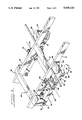
- FIG. 1 is a broken perspective view of the rear portion of the frame assembly of the present invention
- FIG. 2 is a broken plan view of the rearmost portion of the frame and suspension assembly of the present invention.
- FIG. 3 is a broken side elevation view of the frame assembly of FIG. 2;
- FIG. 4 is a rear elevation view of a portion of the assembly of FIG. 2 showing the positioning of the anti-sway bar therein;
- FIG. 5 is an exploded view of a reinforcement means used to reinforce the frame rail in the assembly of present invention.
- FIG. 6 is an exploded broken perspective view of an embodiment of a lower mounting plate for an air spring according to the present invention.
- a frame assembly made according to the principles of the present invention can be incorporated in a motorized vehicle such as a delivery truck, for example, to provide a low frame rail height which, in turn, allows the vehicle to be manufactured with a load carrying surface or compartment which is also low to the ground. In this manner, such a vehicle can be loaded and/or unloaded more conveniently since less effort is required to lift objects from the ground up to the lowered load carrying surface or compartment and vice versa.
- a motorized vehicle such as a delivery truck
- the assembly includes a pair of frame rails 10 and 12 which are connected by at least one cross member 14 and at least one torsion bar 16.
- the assembly incorporates an air spring suspension system in operative association with the frame rails 10 and 12.
- Identical components for the aforementioned air spring suspension system are positioned along both frame rails 10 and 12 and, for ease of explanation, the description herein is limited to the portion of the air spring suspension system associated with the left frame rail 10 as is most clearly illustrated in FIG. 3.
- the suspension system includes a front walking beam mounting bracket 18 with a walking beam 20 pivotally mounted thereto at 21.
- the walking beam 20 is mounted to bracket 18 in a conventional manner and extends rearwardly below the frame rail 10.
- An air spring 22 is positioned at the rearmost end of the walking beam 20.
- the rear axle 24 extends transversely beneath the frame rails 10 and 12 and is secured to the walking beam 20 with L-shaped axle mounting plates 28, 30 and axle cap mounting plate 32. As is shown most clearly in FIG. 3, the axle 24 is positioned between the left and right L-shaped axle mounting plates 28, 30 respectively.
- Each L-shaped axle mounting plate is secured to the walking beam 20, preferably by welding, to prevent displacement of the axle 24 along the walking beam 20 during motorized operation of a vehicle.
- the axle cap mounting plate 32 is bolted over the axle 24 to prevent vertical displacement thereof and a shock absorber 34 is attached at its ends to shock absorber brackets 25 and 27 affixed to the frame rail 10 and to the walking beam 20, respectively.
- the air spring suspension system is configured so that the air spring 22 is mounted outwardly of the frame rail 10.
- the air spring 22 is mounted between lower and upper air bag mounting plates 36, 38 respectively.
- the lower mounting plate 36 is positioned at the rearmost portion of the walking beam 20 and may be secured thereto by a single bolt 39 extending through the lower plate 36 and through the portion of the walking beam supporting that plate.
- the upper air spring mounting plate 38 includes flanges 40 affixed thereto and the plate 38 and flanges 40 are secured to the outermost vertical face of frame rail 10 by welding, for example. As shown, the upper mounting plate 38 is positioned along the outer surface of the frame rail to project outwardly therefrom in a perpendicular relationship with the rail 10 so that the air spring 22, when mounted between plates 36 and 38, projects above the lowermost edge of the frame rail 10.
- the air spring 22 Positioning of the air spring 22 outwardly from the frame rail provides certain advantages over the prior art. Since the air spring 22 is not positioned underneath the frame rails, the lowermost edge of each of the frame rails may extend below the upper mounting plates 38 to provide the desired low frame rail configuration for the frame and suspension assembly of the present invention. Additionally, the suspension system provides improved stability to a vehicle incorporating the assembly herein. More specifically, the placement of air springs 22 outwardly from frame rails 10 and 12 provides an increased center to center distance between the air springs which, in turn, gives greater stability to the associated motor vehicle. Preferably, the center to center distance between the two air springs 22 is between about three and a half feet to about four feet. Further, improved stability can be realized in the choice of air spring incorporated in the assembly. A large diameter air spring will generally require less air pressure to provide a smoother and more stable ride. In this regard, an air spring having a diameter of about ten inches is preferred.
- Pneumatic control means are provided to adjust the air pressure within the air springs 22.
- a control valve 42 may be mounted to the walking beam mounting bracket 18 and above the walking beam 20 for pneumatic control of the air bags 22.
- the two air bags 22 may be inflated and deflated as need requires according to the load being carried by the vehicle incorporating the frame and suspension assembly of the present invention.
- the air springs 22 may be inflated and/or deflated independently.
- the clearance of the rear axle 24 is generally fixed by industry standards, as well as by regulations. Accordingly, it is both desirable and necessary to provide a frame and suspension assembly which is constructed in compliance with those standards and regulations.
- the assembly of the invention is constructed to provide a rear axle clearance of no less than seven inches while providing and maintaining a minimum frame rail height of about twenty three inches.
- each of the frame rails 10 and 12 are provided with a notch, generally indicated at 44, to provide structural clearance for the rear axle 24 under normal on-road operating conditions.
- a notch 44 having a height of approximately three inches and having a base measure of between about seven and about twelve inches and, most preferably, about nine inches, will be sufficient to provide the required clearance.
- the notched frame rail will require reinforcement.
- reinforcement means are provided in the form of reinforcing plate member 46 and reinforcing cap member 48.
- Plate member 46 is preferably welded to the cap member 48.
- the cap member is a curved strip of material which is formed in the same configuration as the notch 44 and the reinforcing plate member 46 is compatibly configured to rest upon the cap member 48 and to extend upwardly therefrom within the frame rail 10.
- cap member 48 will be made of solid steel having a thickness of about one-half inch, a width of about four inches and will have a length sufficient to extend beyond the lateral edges of the notch.
- a cap member 48 having a length of about seventeen inches will generally be adequate to cover a notch having a base measure of about nine inches.
- Reinforcing plate member 46 is preferably made of solid steel with a thickness of between about one inch and about two inches and, most preferably about one and one-half inches and is preferably dimensioned to have a height of between about five and one half inches and about six inches and a length of about twelve inches.
- the aforementioned configuration for the reinforcement means when positioned within the frame rails 10 and 12, will provide adequate reinforcement for the notched area of each frame rail to compensate for the decreased structural strength of the frame rails as a result of notches 44 therein.
- Each notch 44 will provide the necessary clearance between the rear axle 24 and the frame rails 10 and 12 when the assembly is incorporated in a motor vehicle and operated under on-road conditions.
- the reinforcement means preserve the structural integrity of the frame rails while the mounting of air bags 22 outside of frame rails 10 and 12 allows each frame rail to rest in a low-to-the-ground orientation.
- a conventional walking beam for an air spring suspension system is generally dimensioned to have a vertical measure of about four inches when positioned within a frame assembly.
- the walking beam 20 is preferably dimensioned to have a vertical measure of about two inches. In this manner, sufficient clearance is maintained between the ground and the bottom edge of the walking beam 20 when the assembly is incorporated in a motor vehicle.
- the lower air spring mounting plate 36 supports the air spring 22 on the walking beam 20 outwardly of frame rails 10 and 12.
- the walking beam 20 is preferably formed with an angled arm portion 50 for positioning of the lower air spring mounting plate 36 thereon as shown in FIG. 6.
- the angled arm portion 50 extends at an angle from the body portion 52 of the walking beam, and at an acute angle relative to the frame rail associated therewith, to properly orient the lower air spring mounting plate 36 for outward mounting of the air springs 22.
- the body portion 52 is positioned substantially parallel to frame rail 10 for proper support of axle 24 thereon.
- the angled arm portion 50 may be constructed with upper and lower U-shaped halves 54 and 56, respectively.
- the halves 54, 56 are affixed to each other, preferably by welding, and a connecting sleeve 58 fits within the end of body portion 52 for attaching the angled arm portion 50 thereto.
- the connecting sleeve 58 is preferably dimensioned to easily fit within both the body portion 52 and arm portion 50 while providing enough clearance therein to permit the required angling of the angled arm portion 50.
- Connecting sleeve 58 is preferably welded to angled portion 50 and body portion 52 to provide structural rigidity to the walking beam 20.
- the upper U-shaped half 54 preferably extends only partially along the length of angled portion 50 where it terminates to provide an area for positioning lower air bag mounting plate 36 thereon. As shown in FIG. 6, the upper half 54 is compatably dimensioned to fit over connecting sleeve 58. In this manner, the lower edges 55 of upper half 54 can be affixed to the uppermost edges 57 of lower half 56 by welding, for example.
- the forward edge 59 of upper half 54 is angled to provide the desired outward bend for the angled arm portion 50 while simultaneously providing an edge to edge fit with the rearmost edge 61 of body portion 52.
- Additional reinforcement means in the form of a U-shaped sleeve 60 may be positioned within the lower half 56 to both reinforce the rearmost portion of the angle arm portion 50 and to provide a suitable surface for mounting the lower air bag mounting plate 36 thereon.
- End plates 63 and 65 are affixed to the rearmost edges of upper half 54 and lower half 56, respectively, to seal the walking beam 20 against dust, dirt, grease and the like.
- Additional stabilization means are preferably provided in the form of an anti-sway bar 62 as shown in FIGS. 2 and 4.
- the anti-sway bar 62 is preferably pivotally attached at one end 64 to one of the frame rails 10 and at the other end 66 to a walking beam 20 on the opposite side of the frame assembly.
- the axle housing and, more specifically, the differential housing 26 is relieved of the stresses and strains associated with normal road operation for a vehicle incorporating the assembly of the present invention.
- the two sides of the frame and suspension assembly in the present invention are directly connected by anti-sway bar 62 rather than having the sway bar connected to the differential housing and to one of the walking beams 20 or one of the frame rails 10 or 12.
- the rear axle 24 and differential 26 will be mounted on walking beams 20 in a manner which maintains the position of the differential housing below the top of frame rails 10 and 12 even under heavy load conditions.
- a clearance of between about six and about eight inches between the rear axle mounting cap plate 32 and the top of frame rails 10 and 12 will provide the aforementioned preferred position of the differential housing even under heavy load conditions.
- proper air pressure within air springs 22 will help to maintain this preferred clearance in conjunction with the proper selection and maintenance of shock absorbers 34.
- the above-described frame and suspension assembly presents a substantially unobstructed area thereabove so that a vehicle body may be mounted directly on the frame rails without having to be raised to accommodate the differential or other elements of the assembly.
- the vehicle manufacturer may take full advantage of the low frame rail height by positioning the load carrying area of the vehicle directly on the frame rails so that the vehicle is provided with a low-to-the-ground load bearing area.
- such a vehicle can be loaded and unloaded with less effort than has been previously required.
- the lowered load carrying area provides easy access thereto because less effort will be required by those moving a load from the ground up to the lowered load carrying area of the vehicle and vice versa.
- the frame and suspension assembly of the present invention has specific applicability to light duty trucks and the like. More specifically, pick-up trucks, delivery trucks of various configurations and even service vehicles such as ambulances may be advantageously manufactured with a frame assembly constructed in accordance with the teachings of the present invention.
Landscapes
- Engineering & Computer Science (AREA)
- Mechanical Engineering (AREA)
- Vehicle Body Suspensions (AREA)
Abstract
Description
Claims (39)
Priority Applications (1)
| Application Number | Priority Date | Filing Date | Title |
|---|---|---|---|
| US07/433,599 US5039124A (en) | 1989-11-06 | 1989-11-06 | Motor vehicle frame and suspension assembly |
Applications Claiming Priority (1)
| Application Number | Priority Date | Filing Date | Title |
|---|---|---|---|
| US07/433,599 US5039124A (en) | 1989-11-06 | 1989-11-06 | Motor vehicle frame and suspension assembly |
Publications (1)
| Publication Number | Publication Date |
|---|---|
| US5039124A true US5039124A (en) | 1991-08-13 |
Family
ID=23720762
Family Applications (1)
| Application Number | Title | Priority Date | Filing Date |
|---|---|---|---|
| US07/433,599 Expired - Fee Related US5039124A (en) | 1989-11-06 | 1989-11-06 | Motor vehicle frame and suspension assembly |
Country Status (1)
| Country | Link |
|---|---|
| US (1) | US5039124A (en) |
Cited By (35)
| Publication number | Priority date | Publication date | Assignee | Title |
|---|---|---|---|---|
| US5342139A (en) * | 1992-09-30 | 1994-08-30 | Bridgestone/Firestone, Inc. | Snap mounted attachment device |
| US5566971A (en) * | 1995-07-27 | 1996-10-22 | Safari Motor Coaches, Inc. | Vehicle air suspension system |
| US5746441A (en) * | 1996-12-02 | 1998-05-05 | Rockwell Heavy Vehicle Suspension Systems, Inc. | Center beam suspension system |
| WO1998024645A1 (en) * | 1996-12-02 | 1998-06-11 | Suspensions Incorporated | Center beam suspension system |
| WO2000001548A1 (en) | 1998-07-02 | 2000-01-13 | The Boler Company | Trailing arm axle/suspension system |
| ES2153727A1 (en) * | 1997-12-09 | 2001-03-01 | Suspensiones Neumaticas Herrer | Improved pneumatic suspension system for trailers and half-trailers |
| US6241266B1 (en) | 1995-08-03 | 2001-06-05 | Holland Neway International, Inc. | Trailing arm suspension with wrapper compression axle mounting and articulated axle mounting |
| US6328322B1 (en) * | 1998-08-27 | 2001-12-11 | Holland Neway International, Inc. | Drive axle suspension |
| US20030047906A1 (en) * | 2000-06-09 | 2003-03-13 | Hicks William J. | Lightweight narrow-span fifth wheel |
| US20030047907A1 (en) * | 2000-06-09 | 2003-03-13 | Hicks William J. | Integrated fifth wheel and frame suspension |
| US6676143B2 (en) * | 2001-09-28 | 2004-01-13 | Meritor Heavy Vehicle Technology, Llc | Modular suspension arm assembly |
| US20040007844A1 (en) * | 2002-07-12 | 2004-01-15 | Reineck Benjamin R. | Trailing arm suspension anti-roll bar |
| US20040021290A1 (en) * | 2001-06-07 | 2004-02-05 | Hicks William J. | Integrated fifth wheel and frame suspension |
| US6709014B2 (en) | 2001-08-22 | 2004-03-23 | Volvo Trucks North America, Inc. | Heavy duty vehicle frame |
| US20040080136A1 (en) * | 2002-10-29 | 2004-04-29 | Johnsman Daniel W. | Vehicle suspension system |
| US7229086B1 (en) | 2004-06-01 | 2007-06-12 | Robert Louis Rogers | Motor vehicle sway control assembly |
| WO2010132692A1 (en) * | 2009-05-13 | 2010-11-18 | Saf-Holland, Inc. | Suspension system for heavy and vocational vehicles |
| US20110095501A1 (en) * | 2009-10-26 | 2011-04-28 | Hendrickson Usa, L.L.C. | Heavy-duty axle-to-beam connection |
| US7967307B2 (en) * | 2002-07-12 | 2011-06-28 | Arvinmeritor Technology, Llc | Heavy duty trailing arm suspension system |
| US20110175313A1 (en) * | 2010-01-18 | 2011-07-21 | Hendrickson Usa, L.L.C. | Heavy-duty axle-to-beam connection |
| US20110175317A1 (en) * | 2010-01-19 | 2011-07-21 | Lbc Contracting, Ltd. | Vehicle leaf spring to air ride suspension conversion assembly |
| US8328210B2 (en) | 2010-01-20 | 2012-12-11 | Link Suspensions Of Canada Lp | Axle suspension |
| US8465036B2 (en) * | 2011-08-02 | 2013-06-18 | Arvinmeritor Technology, Llc | Side mounted air spring trailing arm suspension |
| US8955860B2 (en) | 2012-03-28 | 2015-02-17 | Saf-Holland, Inc. | Vehicle suspension assembly with integrated torque member and trailing arm mount |
| US20160176439A1 (en) * | 2013-07-29 | 2016-06-23 | Saf-Holland Gmbh | Steering Unit |
| US9809073B2 (en) | 2015-09-29 | 2017-11-07 | Hendrickson Usa, L.L.C. | Tapered axle/suspension system beam for heavy-duty vehicles |
| US20200369140A1 (en) * | 2019-05-20 | 2020-11-26 | Canoo Inc. | Electric Vehicle Platform |
| US11607977B2 (en) | 2019-09-20 | 2023-03-21 | Canoo Technologies Inc. | Vehicle seating systems |
| US11618292B2 (en) | 2019-09-09 | 2023-04-04 | Canoo Technologies Inc. | Suspension system |
| US11742540B2 (en) | 2019-01-07 | 2023-08-29 | Canoo Technologies Inc. | Methods and systems for battery pack thermal management |
| US20240083232A1 (en) * | 2022-09-07 | 2024-03-14 | Harbinger Motors Inc. | Electric commercial vehicle chassis |
| US12168475B2 (en) | 2019-07-02 | 2024-12-17 | Canoo Technologies Inc. | Impact features |
| US12420869B2 (en) | 2019-07-02 | 2025-09-23 | Canoo Technologies Inc. | Method to reduced lateral deflection of longitudinal members in side impact |
| USD1103851S1 (en) | 2022-09-08 | 2025-12-02 | Harbinger Motors Inc. | Beam axle |
| US12594990B1 (en) | 2025-05-08 | 2026-04-07 | Harbinger Motors Inc. | Commercial electric vehicle steering |
Citations (28)
| Publication number | Priority date | Publication date | Assignee | Title |
|---|---|---|---|---|
| US2290620A (en) * | 1940-01-05 | 1942-07-21 | Firestone Tire & Rubber Co | Vehicle suspension |
| GB848416A (en) * | 1956-02-03 | 1960-09-14 | Maschf Augsburg Nuernberg Ag | A wheel springing system for motor vehicles |
| US2995355A (en) * | 1956-11-24 | 1961-08-08 | Daimler Benz Ag | Pneumatic spring system for motor vehicles, particularly buses |
| US3707298A (en) * | 1970-10-06 | 1972-12-26 | Lear Siegler Inc | Suspension structure for land vehicles |
| US3746363A (en) * | 1971-03-29 | 1973-07-17 | Lear Siegler Inc | Suspension for land vehicles |
| US3771812A (en) * | 1972-04-25 | 1973-11-13 | Lear Siegler Inc | Air suspension with improved axle lifting structure |
| US3774948A (en) * | 1971-01-28 | 1973-11-27 | Mercodante J | Combined vehicle chassis and air suspension system |
| US3817550A (en) * | 1972-11-15 | 1974-06-18 | Lear Siegler Inc | Vehicle suspension system and bearing construction therefor |
| US3850445A (en) * | 1974-02-11 | 1974-11-26 | Lear Siegler Inc | Combined air spring and leaf spring suspension |
| US3920283A (en) * | 1974-08-26 | 1975-11-18 | Lear Siegler Inc | Brake responsive load transfer apparatus and method |
| US3921999A (en) * | 1973-06-12 | 1975-11-25 | Lear Siegler Inc | Vehicle suspension construction and sub-assembly therefor |
| US3960388A (en) * | 1975-03-27 | 1976-06-01 | Lear Siegler, Inc. | Vehicle suspension system and alignment mechanism therefor |
| US4193612A (en) * | 1978-06-19 | 1980-03-18 | Lear Siegler, Inc. | Elastomeric suspension system for wheeled vehicles |
| US4262929A (en) * | 1978-12-22 | 1981-04-21 | Lear Siegler, Inc. | Suspension with resilient reaction bar |
| US4322061A (en) * | 1980-02-14 | 1982-03-30 | Lear Siegler, Inc. | Tandem spring suspension with leaf rotation stop |
| US4379572A (en) * | 1980-05-12 | 1983-04-12 | Hedenberg William E | Universal air suspension system |
| US4405154A (en) * | 1981-05-15 | 1983-09-20 | Lear Siegler, Inc. | Multi-axle equilized suspension system |
| GB2139971A (en) * | 1983-05-16 | 1984-11-21 | Maschf Augsburg Nuernberg Ag | Axle suspension for a vehicle |
| US4553773A (en) * | 1983-08-05 | 1985-11-19 | Lear Siegler, Inc. | Load equalizer valve and suspension system |
| US4580798A (en) * | 1984-11-13 | 1986-04-08 | Roelofs Robert E | Air suspension system for the rear end of a motor home |
| US4580809A (en) * | 1984-05-09 | 1986-04-08 | Vehicle Systems, Inc. | Vehicle suspension system |
| US4595216A (en) * | 1984-07-20 | 1986-06-17 | Lear Siegler, Inc. | Vehicle suspension structure |
| US4596402A (en) * | 1981-05-21 | 1986-06-24 | Raidel John E | Wide base air spring suspension with unitized parallelogram stabilization |
| US4615539A (en) * | 1985-02-06 | 1986-10-07 | Lear Siegler, Inc. | Suspension for automotive vehicles |
| US4634141A (en) * | 1984-07-03 | 1987-01-06 | Lear Siegler, Inc. | Axle lift mechanism |
| US4693486A (en) * | 1986-04-09 | 1987-09-15 | Lear Siegler, Inc. | Trailing arm suspension with wrapper compression axle mounting |
| US4700968A (en) * | 1986-04-07 | 1987-10-20 | Lear Siegler, Inc. | Liftable axle with load control |
| US4736958A (en) * | 1986-04-14 | 1988-04-12 | Lear Siegler, Inc. | Air suspension system with automatic air exhaust and inflation |
-
1989
- 1989-11-06 US US07/433,599 patent/US5039124A/en not_active Expired - Fee Related
Patent Citations (29)
| Publication number | Priority date | Publication date | Assignee | Title |
|---|---|---|---|---|
| US2290620A (en) * | 1940-01-05 | 1942-07-21 | Firestone Tire & Rubber Co | Vehicle suspension |
| GB848416A (en) * | 1956-02-03 | 1960-09-14 | Maschf Augsburg Nuernberg Ag | A wheel springing system for motor vehicles |
| US2995355A (en) * | 1956-11-24 | 1961-08-08 | Daimler Benz Ag | Pneumatic spring system for motor vehicles, particularly buses |
| US3707298A (en) * | 1970-10-06 | 1972-12-26 | Lear Siegler Inc | Suspension structure for land vehicles |
| US3774948A (en) * | 1971-01-28 | 1973-11-27 | Mercodante J | Combined vehicle chassis and air suspension system |
| US3746363A (en) * | 1971-03-29 | 1973-07-17 | Lear Siegler Inc | Suspension for land vehicles |
| US3771812A (en) * | 1972-04-25 | 1973-11-13 | Lear Siegler Inc | Air suspension with improved axle lifting structure |
| US3817550A (en) * | 1972-11-15 | 1974-06-18 | Lear Siegler Inc | Vehicle suspension system and bearing construction therefor |
| US3921999A (en) * | 1973-06-12 | 1975-11-25 | Lear Siegler Inc | Vehicle suspension construction and sub-assembly therefor |
| US3850445A (en) * | 1974-02-11 | 1974-11-26 | Lear Siegler Inc | Combined air spring and leaf spring suspension |
| US3920283A (en) * | 1974-08-26 | 1975-11-18 | Lear Siegler Inc | Brake responsive load transfer apparatus and method |
| US3960388A (en) * | 1975-03-27 | 1976-06-01 | Lear Siegler, Inc. | Vehicle suspension system and alignment mechanism therefor |
| US4193612A (en) * | 1978-06-19 | 1980-03-18 | Lear Siegler, Inc. | Elastomeric suspension system for wheeled vehicles |
| US4262929A (en) * | 1978-12-22 | 1981-04-21 | Lear Siegler, Inc. | Suspension with resilient reaction bar |
| US4322061A (en) * | 1980-02-14 | 1982-03-30 | Lear Siegler, Inc. | Tandem spring suspension with leaf rotation stop |
| US4379572A (en) * | 1980-05-12 | 1983-04-12 | Hedenberg William E | Universal air suspension system |
| US4405154A (en) * | 1981-05-15 | 1983-09-20 | Lear Siegler, Inc. | Multi-axle equilized suspension system |
| US4596402A (en) * | 1981-05-21 | 1986-06-24 | Raidel John E | Wide base air spring suspension with unitized parallelogram stabilization |
| GB2139971A (en) * | 1983-05-16 | 1984-11-21 | Maschf Augsburg Nuernberg Ag | Axle suspension for a vehicle |
| US4553773A (en) * | 1983-08-05 | 1985-11-19 | Lear Siegler, Inc. | Load equalizer valve and suspension system |
| US4580809A (en) * | 1984-05-09 | 1986-04-08 | Vehicle Systems, Inc. | Vehicle suspension system |
| US4634141A (en) * | 1984-07-03 | 1987-01-06 | Lear Siegler, Inc. | Axle lift mechanism |
| US4729579A (en) * | 1984-07-03 | 1988-03-08 | Lear Siegler, Inc. | Axle lift mechanism with spring cup wear plate |
| US4595216A (en) * | 1984-07-20 | 1986-06-17 | Lear Siegler, Inc. | Vehicle suspension structure |
| US4580798A (en) * | 1984-11-13 | 1986-04-08 | Roelofs Robert E | Air suspension system for the rear end of a motor home |
| US4615539A (en) * | 1985-02-06 | 1986-10-07 | Lear Siegler, Inc. | Suspension for automotive vehicles |
| US4700968A (en) * | 1986-04-07 | 1987-10-20 | Lear Siegler, Inc. | Liftable axle with load control |
| US4693486A (en) * | 1986-04-09 | 1987-09-15 | Lear Siegler, Inc. | Trailing arm suspension with wrapper compression axle mounting |
| US4736958A (en) * | 1986-04-14 | 1988-04-12 | Lear Siegler, Inc. | Air suspension system with automatic air exhaust and inflation |
Non-Patent Citations (20)
| Title |
|---|
| Advertisement for Hendrickson Turner. * |
| Advertisement for Reyco Transpro, Reyco Industries, Inc., Model 87, 86, 88. * |
| Advertisement for Ridewell Suspensions. * |
| Advertisement for RV Products, Inc. Model T 9AH. * |
| Advertisement for RV Products, Inc. Model T-9AH. |
| Advertisement for Silent Drive, Inc. * |
| Brochure for Henschen Industrial, composite multi axle. * |
| Brochure for Henschen Industrial, composite multi-axle. |
| Brochure of Air Ax Suspension Systems. * |
| Brochure of Air Lift Company. * |
| Brochure of Air-Ax Suspension Systems. |
| Brochure of Dyneer, Granning Division, Models RD 1000, RD 740, RT 500 Air Suspensions. * |
| Brochure of Jet Company. * |
| Flyer of E Z Ride Suspensions, CLS 9500/8500, MTS 1800, CAC 1400 Suspensions. * |
| Flyer of E-Z Ride Suspensions, CLS 9500/8500, MTS 1800, CAC 1400 Suspensions. |
| Flyers for Silent Drive, Inc., Suspension Component Group Model AD 310, ALD 320. * |
| Flyers for Silent Drive, Inc., Suspension Component Group Model AD-310, ALD-320. |
| Illustrated installation instructions for Silent Drive, Inc. Suspension Component Group, Model ALD 330. * |
| Illustrated installation instructions for Silent Drive, Inc. Suspension Component Group, Model ALD-330. |
| Neway Corp., Service parts/price book, Effective Sep. 15, 1989, Form No. 829. * |
Cited By (62)
| Publication number | Priority date | Publication date | Assignee | Title |
|---|---|---|---|---|
| US5342139A (en) * | 1992-09-30 | 1994-08-30 | Bridgestone/Firestone, Inc. | Snap mounted attachment device |
| EP0590317A3 (en) * | 1992-09-30 | 1996-04-17 | Bridgestone Firestone Inc | Snap mounted attachment device |
| US5566971A (en) * | 1995-07-27 | 1996-10-22 | Safari Motor Coaches, Inc. | Vehicle air suspension system |
| US6491314B2 (en) | 1995-08-03 | 2002-12-10 | The Holland Group, Inc. | Trailing arm suspension with wrapper compression axle mounting and articulated axle mounting |
| US6241266B1 (en) | 1995-08-03 | 2001-06-05 | Holland Neway International, Inc. | Trailing arm suspension with wrapper compression axle mounting and articulated axle mounting |
| US5791681A (en) * | 1996-12-02 | 1998-08-11 | Rockwell Heavy Vehicle Suspension Systems, Inc. | Single beam suspension system |
| WO1998024646A1 (en) * | 1996-12-02 | 1998-06-11 | Suspensions Incorporated | Center beam suspension system |
| US5908198A (en) * | 1996-12-02 | 1999-06-01 | Meritor Heavy Vehicle Systems, Llc | Center beam suspension system |
| WO1998024645A1 (en) * | 1996-12-02 | 1998-06-11 | Suspensions Incorporated | Center beam suspension system |
| US5746441A (en) * | 1996-12-02 | 1998-05-05 | Rockwell Heavy Vehicle Suspension Systems, Inc. | Center beam suspension system |
| ES2153727A1 (en) * | 1997-12-09 | 2001-03-01 | Suspensiones Neumaticas Herrer | Improved pneumatic suspension system for trailers and half-trailers |
| WO2000001548A1 (en) | 1998-07-02 | 2000-01-13 | The Boler Company | Trailing arm axle/suspension system |
| US6508482B2 (en) | 1998-07-02 | 2003-01-21 | The Boler Company. | Trailing arm axle/suspension system |
| US6328322B1 (en) * | 1998-08-27 | 2001-12-11 | Holland Neway International, Inc. | Drive axle suspension |
| US20030047906A1 (en) * | 2000-06-09 | 2003-03-13 | Hicks William J. | Lightweight narrow-span fifth wheel |
| US7416204B2 (en) | 2000-06-09 | 2008-08-26 | Saf-Holland, Inc. | Lightweight narrow-span fifth wheel |
| US20030047907A1 (en) * | 2000-06-09 | 2003-03-13 | Hicks William J. | Integrated fifth wheel and frame suspension |
| US20100244406A1 (en) * | 2000-06-09 | 2010-09-30 | Hicks William J | Lightweight narrow-span fifth wheel |
| US20080265545A1 (en) * | 2000-06-09 | 2008-10-30 | Hicks William J | Lightweight narrow-span fifth wheel |
| US20040021290A1 (en) * | 2001-06-07 | 2004-02-05 | Hicks William J. | Integrated fifth wheel and frame suspension |
| US6709014B2 (en) | 2001-08-22 | 2004-03-23 | Volvo Trucks North America, Inc. | Heavy duty vehicle frame |
| US6676143B2 (en) * | 2001-09-28 | 2004-01-13 | Meritor Heavy Vehicle Technology, Llc | Modular suspension arm assembly |
| US20040007844A1 (en) * | 2002-07-12 | 2004-01-15 | Reineck Benjamin R. | Trailing arm suspension anti-roll bar |
| US7967307B2 (en) * | 2002-07-12 | 2011-06-28 | Arvinmeritor Technology, Llc | Heavy duty trailing arm suspension system |
| US6871864B2 (en) * | 2002-07-12 | 2005-03-29 | Arvinmeritor Technology, Llc | Trailing arm suspension anti-roll bar |
| US6857647B2 (en) * | 2002-10-29 | 2005-02-22 | International Truck Intellectual Property Company, Llc | Vehicle suspension system |
| US20040080136A1 (en) * | 2002-10-29 | 2004-04-29 | Johnsman Daniel W. | Vehicle suspension system |
| US7364175B2 (en) | 2004-06-01 | 2008-04-29 | Robert Rogers | Motor vehicle sway control assembly |
| US20070152419A1 (en) * | 2004-06-01 | 2007-07-05 | Robert Rogers | Motor vehicle sway control assembly |
| US7229086B1 (en) | 2004-06-01 | 2007-06-12 | Robert Louis Rogers | Motor vehicle sway control assembly |
| US20110115184A1 (en) * | 2009-05-13 | 2011-05-19 | Marc Johnson | Suspension system for heavy and vocational vehicles |
| US8371596B2 (en) * | 2009-05-13 | 2013-02-12 | Saf-Holland, Inc. | Suspension system for heavy and vocational vehicles |
| WO2010132692A1 (en) * | 2009-05-13 | 2010-11-18 | Saf-Holland, Inc. | Suspension system for heavy and vocational vehicles |
| US20110095501A1 (en) * | 2009-10-26 | 2011-04-28 | Hendrickson Usa, L.L.C. | Heavy-duty axle-to-beam connection |
| US8490989B2 (en) | 2009-10-26 | 2013-07-23 | Hendrickson Usa, L.L.C. | Heavy-duty axle-to-beam connection |
| US20110175313A1 (en) * | 2010-01-18 | 2011-07-21 | Hendrickson Usa, L.L.C. | Heavy-duty axle-to-beam connection |
| US8292313B2 (en) | 2010-01-18 | 2012-10-23 | Hendrickson Usa, L.L.C. | Heavy-duty axle-to-beam connection |
| US20110175317A1 (en) * | 2010-01-19 | 2011-07-21 | Lbc Contracting, Ltd. | Vehicle leaf spring to air ride suspension conversion assembly |
| US8870203B2 (en) * | 2010-01-19 | 2014-10-28 | Lbc Contracting, Ltd. | Vehicle leaf spring to air ride suspension conversion assembly |
| US8328210B2 (en) | 2010-01-20 | 2012-12-11 | Link Suspensions Of Canada Lp | Axle suspension |
| US8465036B2 (en) * | 2011-08-02 | 2013-06-18 | Arvinmeritor Technology, Llc | Side mounted air spring trailing arm suspension |
| US8955860B2 (en) | 2012-03-28 | 2015-02-17 | Saf-Holland, Inc. | Vehicle suspension assembly with integrated torque member and trailing arm mount |
| US20160176439A1 (en) * | 2013-07-29 | 2016-06-23 | Saf-Holland Gmbh | Steering Unit |
| US9707999B2 (en) * | 2013-07-29 | 2017-07-18 | Saf-Holland Gmbh | Steering unit |
| US9809073B2 (en) | 2015-09-29 | 2017-11-07 | Hendrickson Usa, L.L.C. | Tapered axle/suspension system beam for heavy-duty vehicles |
| US11742540B2 (en) | 2019-01-07 | 2023-08-29 | Canoo Technologies Inc. | Methods and systems for battery pack thermal management |
| US20200369140A1 (en) * | 2019-05-20 | 2020-11-26 | Canoo Inc. | Electric Vehicle Platform |
| US11833895B2 (en) * | 2019-05-20 | 2023-12-05 | Canoo Technologies Inc. | Electric vehicle platform |
| US12103375B2 (en) | 2019-05-20 | 2024-10-01 | Canoo Technologies Inc. | Electric vehicle platform |
| US12168475B2 (en) | 2019-07-02 | 2024-12-17 | Canoo Technologies Inc. | Impact features |
| US12420869B2 (en) | 2019-07-02 | 2025-09-23 | Canoo Technologies Inc. | Method to reduced lateral deflection of longitudinal members in side impact |
| US12533921B2 (en) | 2019-09-09 | 2026-01-27 | Canoo Technologies Inc. | Suspension system |
| US11618292B2 (en) | 2019-09-09 | 2023-04-04 | Canoo Technologies Inc. | Suspension system |
| US11738670B2 (en) | 2019-09-20 | 2023-08-29 | Canoo Technologies Inc. | Vehicle seating systems |
| US11607977B2 (en) | 2019-09-20 | 2023-03-21 | Canoo Technologies Inc. | Vehicle seating systems |
| US12017520B2 (en) | 2022-09-07 | 2024-06-25 | Harbinger Motors Inc. | Electric commercial vehicle rear axle |
| US12351011B2 (en) * | 2022-09-07 | 2025-07-08 | Harbinger Motors Inc. | Axle arrangement for an electric commercial vehicle chassis |
| US12011985B2 (en) * | 2022-09-07 | 2024-06-18 | Harbinger Motors Inc. | Axle arrangement for an electric commercial vehicle chassis |
| US20240083232A1 (en) * | 2022-09-07 | 2024-03-14 | Harbinger Motors Inc. | Electric commercial vehicle chassis |
| US12583301B2 (en) | 2022-09-07 | 2026-03-24 | Harbinger Motors Inc. | Electric commercial vehicle rear axle |
| USD1103851S1 (en) | 2022-09-08 | 2025-12-02 | Harbinger Motors Inc. | Beam axle |
| US12594990B1 (en) | 2025-05-08 | 2026-04-07 | Harbinger Motors Inc. | Commercial electric vehicle steering |
Similar Documents
| Publication | Publication Date | Title |
|---|---|---|
| US5039124A (en) | Motor vehicle frame and suspension assembly | |
| EP2230106B1 (en) | Vehicle suspension | |
| US5988672A (en) | Suspension system with integral box beam | |
| US7766352B2 (en) | Roll stable vehicle suspension system | |
| US5649719A (en) | Linkage suspension system | |
| CA2253670C (en) | Suspension system with laminated beam | |
| US6471223B1 (en) | Auxiliary lift axle suspension | |
| US5088763A (en) | Apparatus for mounting a trailing arm air suspension to a sliding frame | |
| US5853183A (en) | Lift mechanism for vehicle suspensions | |
| US7198298B2 (en) | Movable subframe for semi-trailers | |
| US6286857B1 (en) | Trunnion air-ride suspension | |
| US4500112A (en) | Wide base air spring suspension system | |
| US4174855A (en) | Wheeled vehicle axle suspension system | |
| CA2441770C (en) | Highway/rail trailer axle/suspension lift assembly | |
| WO2012071337A2 (en) | Side-beam lift assembly for heavy-duty vehicles | |
| US4529224A (en) | Wide base air spring suspension assembly | |
| US5951032A (en) | Air suspension system | |
| US5088758A (en) | Suspension system for semi trailers | |
| AU2002307353A1 (en) | Lift axle suspension | |
| US5915705A (en) | Lift mechanism for vehicle suspensions | |
| US7178817B1 (en) | Trailing arm suspension system | |
| US6857647B2 (en) | Vehicle suspension system | |
| US5228718A (en) | Air bag and walking beam construction | |
| US6382659B1 (en) | Load distributing tandem suspension assembly | |
| US4596402A (en) | Wide base air spring suspension with unitized parallelogram stabilization |
Legal Events
| Date | Code | Title | Description |
|---|---|---|---|
| AS | Assignment |
Owner name: COMPUTER DESIGNED CHASSIS, INC., PAXTON, IL A CORP Free format text: ASSIGNMENT OF ASSIGNORS INTEREST.;ASSIGNOR:WIDMER, GERALD L.;REEL/FRAME:005665/0155 Effective date: 19910325 |
|
| AS | Assignment |
Owner name: COMPUTER DESIGNED CHASSIS CORP., AN IL CORP., ILLI Free format text: ASSIGNMENT OF ASSIGNORS INTEREST.;ASSIGNOR:COMPUTER DESIGNED CHASSIS, INC.;REEL/FRAME:006314/0371 Effective date: 19921123 |
|
| AS | Assignment |
Owner name: CARPENTER MANUFACTURING, INC., INDIANA Free format text: ASSIGNMENT OF ASSIGNORS INTEREST;ASSIGNOR:COMPUTER DESIGNED CHASSIS CORP.;REEL/FRAME:006617/0866 Effective date: 19930219 |
|
| AS | Assignment |
Owner name: STAR BANK, NATIONAL ASSOCIATION, OHIO Free format text: MORTGAGE;ASSIGNOR:CARPENTER MANUFACTURING, INC.;REEL/FRAME:006818/0069 Effective date: 19931221 |
|
| REMI | Maintenance fee reminder mailed | ||
| LAPS | Lapse for failure to pay maintenance fees | ||
| FP | Lapsed due to failure to pay maintenance fee |
Effective date: 19950816 |
|
| AS | Assignment |
Owner name: CARPENTER MANUFACTURING, INC., INDIANA Free format text: RELEASE OF MORTGAGE;ASSIGNOR:STAR BANK, NATIONAL ASSOCIATION;REEL/FRAME:007991/0213 Effective date: 19960307 |
|
| AS | Assignment |
Owner name: CARPENTER INDUSTRIES, LLC, INDIANA Free format text: LIQUIDATION AND REFORMATION OF LIMITED LIABILITY COMPANY;ASSIGNOR:CARPENTER MANUFACTURING, INC.;REEL/FRAME:008194/0202 Effective date: 19960628 |
|
| AS | Assignment |
Owner name: CARPENTER INDUSTRIES, INC., INDIANA Free format text: ASSIGNMENT OF ASSIGNORS INTEREST;ASSIGNOR:CARPENTER INDUSTRIES, LLC;REEL/FRAME:008321/0704 Effective date: 19970106 |
|
| STCH | Information on status: patent discontinuation |
Free format text: PATENT EXPIRED DUE TO NONPAYMENT OF MAINTENANCE FEES UNDER 37 CFR 1.362 |