US5038299A - Serial/parallel transfer apparatus - Google Patents
Serial/parallel transfer apparatus Download PDFInfo
- Publication number
- US5038299A US5038299A US07/414,601 US41460189A US5038299A US 5038299 A US5038299 A US 5038299A US 41460189 A US41460189 A US 41460189A US 5038299 A US5038299 A US 5038299A
- Authority
- US
- United States
- Prior art keywords
- connector
- transfer
- program
- electronic apparatus
- interface
- Prior art date
- Legal status (The legal status is an assumption and is not a legal conclusion. Google has not performed a legal analysis and makes no representation as to the accuracy of the status listed.)
- Expired - Fee Related
Links
Images


Classifications
-
- G—PHYSICS
- G06—COMPUTING; CALCULATING OR COUNTING
- G06F—ELECTRIC DIGITAL DATA PROCESSING
- G06F13/00—Interconnection of, or transfer of information or other signals between, memories, input/output devices or central processing units
- G06F13/38—Information transfer, e.g. on bus
-
- G—PHYSICS
- G06—COMPUTING; CALCULATING OR COUNTING
- G06F—ELECTRIC DIGITAL DATA PROCESSING
- G06F3/00—Input arrangements for transferring data to be processed into a form capable of being handled by the computer; Output arrangements for transferring data from processing unit to output unit, e.g. interface arrangements
- G06F3/12—Digital output to print unit, e.g. line printer, chain printer
- G06F3/1201—Dedicated interfaces to print systems
- G06F3/1202—Dedicated interfaces to print systems specifically adapted to achieve a particular effect
- G06F3/1203—Improving or facilitating administration, e.g. print management
- G06F3/1209—Improving or facilitating administration, e.g. print management resulting in adapted or bridged legacy communication protocols, e.g. emulation, protocol extension
-
- G—PHYSICS
- G06—COMPUTING; CALCULATING OR COUNTING
- G06F—ELECTRIC DIGITAL DATA PROCESSING
- G06F3/00—Input arrangements for transferring data to be processed into a form capable of being handled by the computer; Output arrangements for transferring data from processing unit to output unit, e.g. interface arrangements
- G06F3/12—Digital output to print unit, e.g. line printer, chain printer
- G06F3/1201—Dedicated interfaces to print systems
- G06F3/1223—Dedicated interfaces to print systems specifically adapted to use a particular technique
- G06F3/1236—Connection management
-
- G—PHYSICS
- G06—COMPUTING; CALCULATING OR COUNTING
- G06F—ELECTRIC DIGITAL DATA PROCESSING
- G06F3/00—Input arrangements for transferring data to be processed into a form capable of being handled by the computer; Output arrangements for transferring data from processing unit to output unit, e.g. interface arrangements
- G06F3/12—Digital output to print unit, e.g. line printer, chain printer
- G06F3/1201—Dedicated interfaces to print systems
- G06F3/1278—Dedicated interfaces to print systems specifically adapted to adopt a particular infrastructure
- G06F3/1279—Controller construction, e.g. aspects of the interface hardware
-
- G—PHYSICS
- G06—COMPUTING; CALCULATING OR COUNTING
- G06F—ELECTRIC DIGITAL DATA PROCESSING
- G06F3/00—Input arrangements for transferring data to be processed into a form capable of being handled by the computer; Output arrangements for transferring data from processing unit to output unit, e.g. interface arrangements
- G06F3/12—Digital output to print unit, e.g. line printer, chain printer
- G06F3/1201—Dedicated interfaces to print systems
- G06F3/1278—Dedicated interfaces to print systems specifically adapted to adopt a particular infrastructure
- G06F3/1284—Local printer device
Definitions
- the present invention relates to an electronic apparatus to which a printer is connected via a printer interface, and in particular, to an electronic device of a structure to which both of a parallel transfer printer and a serial transfer printer can be connected.
- the printers can be primarily classified into two kinds, namely, parallel and serial transfer printers.
- a parallel transfer printer print data is processed in a parallel fashion; whereas, in a serial printer, print data is processed in a serial fashion.
- an electronic apparatus for example, a microcomputer or an electronic weighing apparatus transferring operation control signals and print data to such a parallel or serial transfer printer must be provided with the hardware and programs of the parallel transfer specification or the serial transfer specification, respectively.
- FIGS. 4-5 shows a conventional example of a case including an electronic weighing machine as the electronic apparatus.
- the printer is connected, as shown in FIG. 4, to a body 1 of an electronic weighing apparatus having a hardware and a program each dedicated to the parallel transfer.
- the printer is connected, as shown in FIG. 5, to a body 11 of an electronic weighing apparatus having a hardware and a program each dedicated to the serial transfer.
- the electronic weighing apparatus body 1 for the parallel transfer includes a 1-chip CPU 2 therein.
- the 1-chip CPU 2 is provided with a program memory 50 for the parallel transfer.
- such a 1-chip CPU 2 is connected to such components necessary for an electronic weighing apparatus as a key 3, a display section 4, and a load cell 5.
- the 1-chip CPU 2 is connected to a connector 6 on the body side via a data input line, a data output line, etc.
- the connector 6 on the body side is configured to be dedicated to the printer interface 7 for the parallel transfer.
- the printer interface 7 is provided with a connector 8 connected to the connector 6 on the body side, a parallel/parallel interface 9 connected to the connector 8, and a conector 10 connected to the parallel transfer printer.
- FIG. 5 showing the configuration of the electronic weighing apparatus 11 for the serial transfer
- a 1-chip CPU 12 is included in FIG. 5 showing the configuration of the electronic weighing apparatus 11 for the serial transfer.
- the 1-chip CPU 12 is provided with a program 51 for the serial transfer and that, in addition, a connector 16 on the body connected by use of a data bus, a control line, etc. is connected to the 1-chip CPU 12 so as to be dedicated to a serial transfer printer interface 17.
- the printer interface 17 corresponding to the electronic weighing apparatus body 11 is also provided with a connector 18 connected to the connector 16 on the body side, a parallel/serial interface 19 connected to the connector 18 for a parallel/serial conversion, and a connector 10 to be connected to the parallel transfer printer (not shown), which is different from the structure of the printer interface 7 described above.
- the 1-chip CPU 12 is also naturally connected to such components necessary for an electronic weighing apparatus as a key 13, a display section 14, and a load cell 15.
- the problems of the prior art technology will be next described.
- the hardware of the body of the electronic weighing apparatus is structured either for a parallel transfer as shown in FIG. 4 or for a serial transfer as shown in FIG. 5. Consequently, there exists a disadvantage that the electronic weighing apparatus body 1 or 11 can be connected only to a printer of the corresponding transfer system. Namely, when a printer having the different transfer system is to be connected, replacement of the printer interface 7 or 17 is not sufficient, that is, the program memory 50 or 51, the connector 6 or 16, and the like on the electronic weighing apparatus body side 1 or 11 must be respectively modified, which is inconvenient to cope with the different transfer system.
- a program memory containing a parallel transfer program and a serial transfer program
- a connector on the body sided to which a connector of a printer interface of either a parallel transfer or a serial transfer is connected
- judge means for judging which one of the parallel and serial printer interfaces is connected to the connector on the body side, thereby calling from the program memory a program suitable for a type of the printer interface judged by the judge means.
- the apparatus can be adapted for the parallel transfer printer as well as for the serial transfer printer.
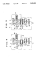
- FIGS. 1(a)-(b) show a schematic circuit diagram illustrating an embodiment of the present invention for the parallel and serial transfer operations
- FIG. 2 is an external perspective view of the apparatus of FIGS. 1(a)-(b);
- FIG. 3 is a flowchrt showing the operation flow in the circuit of FIGS. 1(a)-(b);
- FIG. 4 is a schematic circuit diagram depicting a prior art example of the parallel transfer specification.
- FIG. 5 is a schematic circuit diagram showing a prior art example of the serial transfer specification.
- an electronic weighing apparatus is implemented as the electronic apparatus.
- an electronic weighing apparatus body 21 is provided with a load cell 22 and a circuit board 23.
- a 1-chip CPU 24 On the circuit board 23, there is mounted a 1-chip CPU 24.
- the 1-chip CPU 24 is different from the conventional 1-chip CPU, that is, both of the parallel transfer program and the serial transfer program are included.
- the 1-chip CPU 24 includes a program memory 60 comprising a parallel transfer program memory 60a and a serial transfer program memory 60b.
- the parallel transfer program memory 60a is a memory in which a program for a data transfer to a parallel transfer printer is stored.
- the serial transfer program memory 60a is a memory in which a program for a data transfer to a serial transfer printer is stored.
- the program memory 60 also stores a program judging a state of a connector judge port Pc associated with the connector 27 on the body side (to be described later) and program select means including a program to selectively calling into a work area the parallel transfer program memory 60a or the serial transfer program memory 60b.
- the 1-chip CPU 24 is connected to a key 25, a display section 26, and the load cell 22.
- the 1-chip CPU 24 is connected to the connector 27 on the body side.
- the connector 27 on the body side is provided with a data transfer port 61 linked with lines drawn from the respective ports P 1 -P 13 of the 1-chip CPU 24, a judge port Pc connected to a port other than the ports P 1 -P 13 of the 1-chip CPU 24, and a voltage supply terminal Vs connected to +5V.
- An intermediate point of a line connecting the judge port Pc to the 1-chip CPU 24 is connected via a resistor R to the groung G.
- the judge port Pc, the voltage supply terminal Vs, and the judge port state judge program in the program memory 60 constitute the judge means.
- the printer interface 30 for the parallel transfer and a printer interface 40 for the serial transfer so as to be selectively connected to the electronic weighing apparatus body 21.
- the printer interface 30 includes a connector 31 having a connection pin 62 adaptive to the connector 27 on the body side, a parallel/parallel interface 32 connected to the connector 31 for the parallel processing, and a connector 33 to be connected to a parallel transfer printer (not shown).
- the connection pin 62a of the connector 31 for the judge port Pc of the connector 31 is connected to the connector 27 on the body side
- the voltage supply terminal Vs of the connector 27 on the body side is connected by a short circuit to the judge port Pc, thereby applying +5V also to the judge port Pc.
- the connector 31 connects only the components of the data transfer port 61 corresponding to the ports P 1 -P 10 of the 1-chip CPU 24 to the interface 32.
- the printer interface 40 includes a connector 41 having a connection pin 63 adaptive to the connector 27 on the body side, a parallel/serial interface 42 connected to the connector 41 for effecting a parallel/serial conversion processing, and a connector 43 to be connected to a parallel transfer printer.
- the connection pin 63a of the connector 41 for the judge port Pc is connected to the connector 27 on the body side
- the judge port Pc of the connector 27 on the body side is set to 0 V state (grounded state).
- the connector 41 connects only the components of the data transfer port 61 corresponding to all the ports P 1 -P 13 of the connector 27 on the body side to the interface 42.
- FIG. 1(a) shows a case where the connector 31 of the printer interface 30 is inserted into the connector 27 on the body side to establish the connection, thereby setting a state in which a parallel transfer printer can be connected.
- FIG. 1(b) shows a case where the connector 41 of the printer interface 40 is inserted into the connector 27 on the body side to establish the connection, thereby setting a state in which a parallel transfer printer can be connected.
- the state of the judge port Pc is used to judge which one of the connectors 31 and 41 is connected to the connector 27 on the body side.
- the operation flow ranging from the judgment to the data transmission will be described with reference to the flowchart of FIG. 3.
- +5V is also applied to the judge port Pc of the connector 27 on the body side.
- the 1-chip CPU 24 recognizes that the parallel transfer interface 30 has been connected to the connector 27 on the body side. This causes the program select means in the program memory 60 to call the parallel transfer program memory 60a into the work area.
- the ports P 1 -P 13 are defined for the parallel transfer use.
- the ports P 1 -P 4 are set to the data input use
- the ports P 5 -P 10 are set to the data output use
- the ports P 11 -P 13 are set to the floating state.
- the judge port Pc of the connector 27 on the body side is not supplied with +5V and is in the grounded state of 0 V. That is, the judge port Pc is at a low level.
- the 1-chip CPU 24 recognizes that the serial transfer interface 40 has been connected to the connector 27 on the body side.
- the program select means in the program memory 60 then calls the serial transfer program memory 60b into the work area.
- the ports P 1 -P 13 of the 1-chip CPU 24 are defined for the serial transfer use. That is, the ports P 1 -P 8 are set to the data input use, the ports P 9 -P 13 are set as control lines. This enables the system in the constitution of FIG. 1(b) to be connected to a serial transfer printer.
- the system can be used with a parallel transfer printer and a serial transfer printer only through a connection of the printer interfaces 30 and 40. That is, a printer of an arbitrary transfer type can be used without necessitating the modification of the hardware on the side of the electronic weighing apparatus body 21, thereby implementing an economical system.
- the present invention can also be applied to a microcomputer and the like in addition to the electronic weighing apparatus of the embodiment.
Abstract
Description
Claims (6)
Applications Claiming Priority (2)
| Application Number | Priority Date | Filing Date | Title |
|---|---|---|---|
| JP61-259046 | 1986-10-30 | ||
| JP61259046A JPS63113624A (en) | 1986-10-30 | 1986-10-30 | Printer interface for electronic scale |
Related Parent Applications (1)
| Application Number | Title | Priority Date | Filing Date |
|---|---|---|---|
| US07113862 Continuation | 1987-10-29 |
Publications (1)
| Publication Number | Publication Date |
|---|---|
| US5038299A true US5038299A (en) | 1991-08-06 |
Family
ID=17328579
Family Applications (1)
| Application Number | Title | Priority Date | Filing Date |
|---|---|---|---|
| US07/414,601 Expired - Fee Related US5038299A (en) | 1986-10-30 | 1989-09-29 | Serial/parallel transfer apparatus |
Country Status (3)
| Country | Link |
|---|---|
| US (1) | US5038299A (en) |
| JP (1) | JPS63113624A (en) |
| GB (1) | GB2197099B (en) |
Cited By (37)
| Publication number | Priority date | Publication date | Assignee | Title |
|---|---|---|---|---|
| US5408669A (en) * | 1992-02-07 | 1995-04-18 | Dell Usa, L.P. | Computer system for sensing a cable-connected peripheral and for supplying power thereto |
| US5491830A (en) * | 1992-05-11 | 1996-02-13 | Westinghouse Air Brake Company | Automatic slot identification and address decoder arrangement |
| US5506991A (en) * | 1989-05-15 | 1996-04-09 | Dallas Semiconductor Corporation | Printer port adapter with overlaid one-wire interface for electronic key |
| US5517015A (en) * | 1990-11-19 | 1996-05-14 | Dallas Semiconductor Corporation | Communication module |
| US5535371A (en) * | 1992-02-07 | 1996-07-09 | Dell Usa, L.P. | Portable computer with automatic adaption to different device types on a standard port |
| US5604875A (en) * | 1994-12-19 | 1997-02-18 | Intel Corporation | Method and apparatus for removably connecting either asynchronous or burst cache SRAM to a computer system |
| US5644790A (en) * | 1994-02-16 | 1997-07-01 | Ati Technologies, Inc. | Universal CD ROM interface using single interface connection |
| US5644593A (en) * | 1994-09-02 | 1997-07-01 | Microcom Systems, Inc. | High performance communications interface |
| US5679944A (en) | 1994-06-15 | 1997-10-21 | Dallas Semiconductor Corporation | Portable electronic module having EPROM memory, systems and processes |
| US5787018A (en) * | 1994-12-14 | 1998-07-28 | Dallas Semiconductor Corporation | Systems and methods to gather, store, and transfer information from electro/mechanical tools and instruments |
| US5831827A (en) | 1994-04-28 | 1998-11-03 | Dallas Semiconductor Corporation | Token shaped module for housing an electronic circuit |
| US5845055A (en) * | 1992-07-01 | 1998-12-01 | Canon Kabushiki Kaisha | Output apparatus and method for accomodating a plurality of signal terminal identifications |
| US5848541A (en) | 1994-03-30 | 1998-12-15 | Dallas Semiconductor Corporation | Electrical/mechanical access control systems |
| US5994770A (en) | 1991-07-09 | 1999-11-30 | Dallas Semiconductor Corporation | Portable electronic data carrier |
| EP1039368A2 (en) * | 1999-03-19 | 2000-09-27 | Seiko Epson Corporation | Data communication apparatus |
| US20070076479A1 (en) * | 2005-09-30 | 2007-04-05 | Mosaid Technologies Incorporated | Multiple independent serial link memory |
| US20070153576A1 (en) * | 2005-09-30 | 2007-07-05 | Hakjune Oh | Memory with output control |
| US20070165457A1 (en) * | 2005-09-30 | 2007-07-19 | Jin-Ki Kim | Nonvolatile memory system |
| US20070234071A1 (en) * | 2006-03-28 | 2007-10-04 | Mosaid Technologies Incorporated | Asynchronous ID generation |
| US20070230253A1 (en) * | 2006-03-29 | 2007-10-04 | Jin-Ki Kim | Non-volatile semiconductor memory with page erase |
| US20070233903A1 (en) * | 2006-03-28 | 2007-10-04 | Hong Beom Pyeon | Daisy chain cascade configuration recognition technique |
| US20080137467A1 (en) * | 2006-12-06 | 2008-06-12 | Mosaid Technologies Incorporated | Apparatus and method for capturing serial input data |
| US20080198682A1 (en) * | 2007-02-16 | 2008-08-21 | Mosaid Technologies Incorporated | Semiconductor device and method for selection and de-selection of memory devices interconnected in series |
| US20080201548A1 (en) * | 2007-02-16 | 2008-08-21 | Mosaid Technologies Incorporated | System having one or more memory devices |
| US20080209108A1 (en) * | 2007-02-22 | 2008-08-28 | Hong Beom Pyeon | System and method of page buffer operation for memory devices |
| US20080209110A1 (en) * | 2007-02-22 | 2008-08-28 | Mosaid Technologies Incorporated | Apparatus and method of page program operation for memory devices with mirror back-up of data |
| US20080205187A1 (en) * | 2007-02-22 | 2008-08-28 | Mosaid Technologies Incorporated | Data flow control in multiple independent port |
| US20090021992A1 (en) * | 2007-07-18 | 2009-01-22 | Hakjune Oh | Memory with data control |
| US20100091538A1 (en) * | 2008-10-14 | 2010-04-15 | Mosaid Technologies Incorporated | Bridge device architecture for connecting discrete memory devices to a system |
| US20100091536A1 (en) * | 2008-10-14 | 2010-04-15 | Mosaid Technologies Incorporated | Composite memory having a bridging device for connecting discrete memory devices to a system |
| US20100115214A1 (en) * | 2008-11-04 | 2010-05-06 | Mosaid Technologies Incorporated | Bridging device having a configurable virtual page size |
| US20100115172A1 (en) * | 2008-11-04 | 2010-05-06 | Mosaid Technologies Incorporated | Bridge device having a virtual page buffer |
| US7747833B2 (en) | 2005-09-30 | 2010-06-29 | Mosaid Technologies Incorporated | Independent link and bank selection |
| US20110131383A1 (en) * | 2006-08-22 | 2011-06-02 | Mosaid Technologies Incorporated | Modular command structure for memory and memory system |
| US8825967B2 (en) | 2011-12-08 | 2014-09-02 | Conversant Intellectual Property Management Inc. | Independent write and read control in serially-connected devices |
| US9240227B2 (en) | 2005-09-30 | 2016-01-19 | Conversant Intellectual Property Management Inc. | Daisy chain cascading devices |
| US11948629B2 (en) | 2005-09-30 | 2024-04-02 | Mosaid Technologies Incorporated | Non-volatile memory device with concurrent bank operations |
Families Citing this family (4)
| Publication number | Priority date | Publication date | Assignee | Title |
|---|---|---|---|---|
| JPH01233613A (en) * | 1988-03-07 | 1989-09-19 | Internatl Business Mach Corp <Ibm> | Printer having single connector for parallel/series communication |
| JPH04242287A (en) * | 1991-01-17 | 1992-08-28 | Mitsubishi Electric Corp | Image processor |
| JPH07254991A (en) * | 1994-03-15 | 1995-10-03 | Canon Inc | System, device and method for processing color image |
| US6731403B1 (en) | 1994-03-15 | 2004-05-04 | Canon Kabushiki Kaisha | Color image process system, color image apparatus, color image processing method |
Citations (6)
| Publication number | Priority date | Publication date | Assignee | Title |
|---|---|---|---|---|
| US4079452A (en) * | 1976-06-15 | 1978-03-14 | Bunker Ramo Corporation | Programmable controller with modular firmware for communication control |
| US4174536A (en) * | 1977-01-21 | 1979-11-13 | Massachusetts Institute Of Technology | Digital communications controller with firmware control |
| US4437157A (en) * | 1978-07-20 | 1984-03-13 | Sperry Corporation | Dynamic subchannel allocation |
| JPS59204888A (en) * | 1983-05-07 | 1984-11-20 | カシオ計算機株式会社 | Electronic musical instrument system |
| EP0139756A1 (en) * | 1983-03-07 | 1985-05-08 | Matsushita Electric Industrial Co., Ltd. | Rechargeable electrochemical apparatus and negative pole therefor |
| US4638422A (en) * | 1983-05-19 | 1987-01-20 | Elwyn Rees | Data entry interface assembly |
Family Cites Families (3)
| Publication number | Priority date | Publication date | Assignee | Title |
|---|---|---|---|---|
| JPS59218534A (en) * | 1983-03-24 | 1984-12-08 | Fanuc Ltd | Connection control system of external device |
| JPS6063565A (en) * | 1983-09-17 | 1985-04-11 | Ricoh Co Ltd | Interface system in copying system |
| JPS61246830A (en) * | 1985-04-25 | 1986-11-04 | Canon Inc | Electronic typewriter |
-
1986
- 1986-10-30 JP JP61259046A patent/JPS63113624A/en active Pending
-
1987
- 1987-10-26 GB GB8724992A patent/GB2197099B/en not_active Expired - Lifetime
-
1989
- 1989-09-29 US US07/414,601 patent/US5038299A/en not_active Expired - Fee Related
Patent Citations (6)
| Publication number | Priority date | Publication date | Assignee | Title |
|---|---|---|---|---|
| US4079452A (en) * | 1976-06-15 | 1978-03-14 | Bunker Ramo Corporation | Programmable controller with modular firmware for communication control |
| US4174536A (en) * | 1977-01-21 | 1979-11-13 | Massachusetts Institute Of Technology | Digital communications controller with firmware control |
| US4437157A (en) * | 1978-07-20 | 1984-03-13 | Sperry Corporation | Dynamic subchannel allocation |
| EP0139756A1 (en) * | 1983-03-07 | 1985-05-08 | Matsushita Electric Industrial Co., Ltd. | Rechargeable electrochemical apparatus and negative pole therefor |
| JPS59204888A (en) * | 1983-05-07 | 1984-11-20 | カシオ計算機株式会社 | Electronic musical instrument system |
| US4638422A (en) * | 1983-05-19 | 1987-01-20 | Elwyn Rees | Data entry interface assembly |
Cited By (102)
| Publication number | Priority date | Publication date | Assignee | Title |
|---|---|---|---|---|
| US5506991A (en) * | 1989-05-15 | 1996-04-09 | Dallas Semiconductor Corporation | Printer port adapter with overlaid one-wire interface for electronic key |
| US6217213B1 (en) | 1990-05-15 | 2001-04-17 | Dallas Semiconductor Corporation | Temperature sensing systems and methods |
| US6112275A (en) * | 1990-05-15 | 2000-08-29 | Dallas Semiconductor Corporation | Method of communicating over a single wire bus between a host device and a module device which measures thermal accumulation over time |
| US5619066A (en) * | 1990-05-15 | 1997-04-08 | Dallas Semiconductor Corporation | Memory for an electronic token |
| US5517015A (en) * | 1990-11-19 | 1996-05-14 | Dallas Semiconductor Corporation | Communication module |
| US5761697A (en) * | 1990-11-19 | 1998-06-02 | Dallas Semiconductor Corporation | Identifiable modules on a serial bus system and corresponding identification methods |
| US5994770A (en) | 1991-07-09 | 1999-11-30 | Dallas Semiconductor Corporation | Portable electronic data carrier |
| US5535371A (en) * | 1992-02-07 | 1996-07-09 | Dell Usa, L.P. | Portable computer with automatic adaption to different device types on a standard port |
| US5408669A (en) * | 1992-02-07 | 1995-04-18 | Dell Usa, L.P. | Computer system for sensing a cable-connected peripheral and for supplying power thereto |
| US5491830A (en) * | 1992-05-11 | 1996-02-13 | Westinghouse Air Brake Company | Automatic slot identification and address decoder arrangement |
| US5845055A (en) * | 1992-07-01 | 1998-12-01 | Canon Kabushiki Kaisha | Output apparatus and method for accomodating a plurality of signal terminal identifications |
| US5644790A (en) * | 1994-02-16 | 1997-07-01 | Ati Technologies, Inc. | Universal CD ROM interface using single interface connection |
| US5848541A (en) | 1994-03-30 | 1998-12-15 | Dallas Semiconductor Corporation | Electrical/mechanical access control systems |
| US5831827A (en) | 1994-04-28 | 1998-11-03 | Dallas Semiconductor Corporation | Token shaped module for housing an electronic circuit |
| US5679944A (en) | 1994-06-15 | 1997-10-21 | Dallas Semiconductor Corporation | Portable electronic module having EPROM memory, systems and processes |
| US5729573A (en) * | 1994-09-02 | 1998-03-17 | Microcom Systems, Inc. | High performance communications interface |
| US5644593A (en) * | 1994-09-02 | 1997-07-01 | Microcom Systems, Inc. | High performance communications interface |
| US5787018A (en) * | 1994-12-14 | 1998-07-28 | Dallas Semiconductor Corporation | Systems and methods to gather, store, and transfer information from electro/mechanical tools and instruments |
| US5604875A (en) * | 1994-12-19 | 1997-02-18 | Intel Corporation | Method and apparatus for removably connecting either asynchronous or burst cache SRAM to a computer system |
| EP1039368A2 (en) * | 1999-03-19 | 2000-09-27 | Seiko Epson Corporation | Data communication apparatus |
| EP1039368A3 (en) * | 1999-03-19 | 2002-11-13 | Seiko Epson Corporation | Data communication apparatus |
| US6937355B1 (en) | 1999-03-19 | 2005-08-30 | Seiko Epson Corporation | Data communications apparatus for resuming data transfer after interruption |
| US20070165457A1 (en) * | 2005-09-30 | 2007-07-19 | Jin-Ki Kim | Nonvolatile memory system |
| US8199598B2 (en) | 2005-09-30 | 2012-06-12 | Mosaid Technologies Incorporated | Memory with output control |
| US7747833B2 (en) | 2005-09-30 | 2010-06-29 | Mosaid Technologies Incorporated | Independent link and bank selection |
| US20070076479A1 (en) * | 2005-09-30 | 2007-04-05 | Mosaid Technologies Incorporated | Multiple independent serial link memory |
| US11948629B2 (en) | 2005-09-30 | 2024-04-02 | Mosaid Technologies Incorporated | Non-volatile memory device with concurrent bank operations |
| US11600323B2 (en) | 2005-09-30 | 2023-03-07 | Mosaid Technologies Incorporated | Non-volatile memory device with concurrent bank operations |
| US9240227B2 (en) | 2005-09-30 | 2016-01-19 | Conversant Intellectual Property Management Inc. | Daisy chain cascading devices |
| US9230654B2 (en) | 2005-09-30 | 2016-01-05 | Conversant Intellectual Property Management Inc. | Method and system for accessing a flash memory device |
| US8743610B2 (en) | 2005-09-30 | 2014-06-03 | Conversant Intellectual Property Management Inc. | Method and system for accessing a flash memory device |
| US8738879B2 (en) | 2005-09-30 | 2014-05-27 | Conversant Intellectual Property Managament Inc. | Independent link and bank selection |
| US8654601B2 (en) | 2005-09-30 | 2014-02-18 | Mosaid Technologies Incorporated | Memory with output control |
| US8427897B2 (en) | 2005-09-30 | 2013-04-23 | Mosaid Technologies Incorporated | Memory with output control |
| US8285960B2 (en) | 2005-09-30 | 2012-10-09 | Mosaid Technologies Incorporated | Independent link and bank selection |
| US20070153576A1 (en) * | 2005-09-30 | 2007-07-05 | Hakjune Oh | Memory with output control |
| US20080279003A1 (en) * | 2005-09-30 | 2008-11-13 | Mosaid Technologies Incorporated | Multiple independent serial link memory |
| US8000144B2 (en) | 2005-09-30 | 2011-08-16 | Mosaid Technologies Incorporated | Method and system for accessing a flash memory device |
| US20090073768A1 (en) * | 2005-09-30 | 2009-03-19 | Mosaid Technologies Incorporated | Memory with output control |
| US7515471B2 (en) * | 2005-09-30 | 2009-04-07 | Mosaid Technologies Incorporated | Memory with output control |
| US20110179245A1 (en) * | 2005-09-30 | 2011-07-21 | Mosaid Technologies Incorporated | Independent link and bank selection |
| US7652922B2 (en) | 2005-09-30 | 2010-01-26 | Mosaid Technologies Incorporated | Multiple independent serial link memory |
| US20100030951A1 (en) * | 2005-09-30 | 2010-02-04 | Mosaid Technologies Incorporated | Nonvolatile memory system |
| US7945755B2 (en) | 2005-09-30 | 2011-05-17 | Mosaid Technologies Incorporated | Independent link and bank selection |
| US20110002171A1 (en) * | 2005-09-30 | 2011-01-06 | Mosaid Technologies Incorporated | Memory with output control |
| US7826294B2 (en) | 2005-09-30 | 2010-11-02 | Mosaid Technologies Incorporated | Memory with output control |
| US20100199057A1 (en) * | 2005-09-30 | 2010-08-05 | Mosaid Technologies Incorporated | Independent link and bank selection |
| US20100182838A1 (en) * | 2005-09-30 | 2010-07-22 | Mosaid Technologies Incorporated | Flash memory device with data output control |
| US7719892B2 (en) | 2005-09-30 | 2010-05-18 | Mosaid Technologies Incorproated | Flash memory device with data output control |
| US20070234071A1 (en) * | 2006-03-28 | 2007-10-04 | Mosaid Technologies Incorporated | Asynchronous ID generation |
| US20070233903A1 (en) * | 2006-03-28 | 2007-10-04 | Hong Beom Pyeon | Daisy chain cascade configuration recognition technique |
| US8069328B2 (en) | 2006-03-28 | 2011-11-29 | Mosaid Technologies Incorporated | Daisy chain cascade configuration recognition technique |
| US8364861B2 (en) | 2006-03-28 | 2013-01-29 | Mosaid Technologies Incorporated | Asynchronous ID generation |
| US7872921B2 (en) | 2006-03-29 | 2011-01-18 | Mosaid Technologies Incorporated | Non-volatile semiconductor memory with page erase |
| US20070230253A1 (en) * | 2006-03-29 | 2007-10-04 | Jin-Ki Kim | Non-volatile semiconductor memory with page erase |
| US7995401B2 (en) | 2006-03-29 | 2011-08-09 | Mosaid Technologies Incorporated | Non-volatile semiconductor memory with page erase |
| US7551492B2 (en) | 2006-03-29 | 2009-06-23 | Mosaid Technologies, Inc. | Non-volatile semiconductor memory with page erase |
| US8213240B2 (en) | 2006-03-29 | 2012-07-03 | Mosaid Technologies Incorporated | Non-volatile semiconductor memory with page erase |
| US8559237B2 (en) | 2006-03-29 | 2013-10-15 | Mosaid Technologies Incorporated | Non-volatile semiconductor memory with page erase |
| US20110069551A1 (en) * | 2006-03-29 | 2011-03-24 | Mosaid Technologies Incorporated | Non-Volatile Semiconductor Memory with Page Erase |
| US20110131383A1 (en) * | 2006-08-22 | 2011-06-02 | Mosaid Technologies Incorporated | Modular command structure for memory and memory system |
| US8904046B2 (en) | 2006-12-06 | 2014-12-02 | Conversant Intellectual Property Management Inc. | Apparatus and method for capturing serial input data |
| US20100332685A1 (en) * | 2006-12-06 | 2010-12-30 | Mosaid Technologies Incorporated | Apparatus and method for capturing serial input data |
| US7818464B2 (en) | 2006-12-06 | 2010-10-19 | Mosaid Technologies Incorporated | Apparatus and method for capturing serial input data |
| US20080137467A1 (en) * | 2006-12-06 | 2008-06-12 | Mosaid Technologies Incorporated | Apparatus and method for capturing serial input data |
| US7751272B2 (en) | 2007-02-16 | 2010-07-06 | Mosaid Technologies Incorporated | Semiconductor device and method for selection and de-selection of memory devices interconnected in series |
| US20080201588A1 (en) * | 2007-02-16 | 2008-08-21 | Mosaid Technologies Incorporated | Semiconductor device and method for reducing power consumption in a system having interconnected devices |
| US20080201548A1 (en) * | 2007-02-16 | 2008-08-21 | Mosaid Technologies Incorporated | System having one or more memory devices |
| US8812768B2 (en) | 2007-02-16 | 2014-08-19 | Conversant Intellectual Property Management Inc. | System having one or more memory devices |
| US20080198682A1 (en) * | 2007-02-16 | 2008-08-21 | Mosaid Technologies Incorporated | Semiconductor device and method for selection and de-selection of memory devices interconnected in series |
| US20080209108A1 (en) * | 2007-02-22 | 2008-08-28 | Hong Beom Pyeon | System and method of page buffer operation for memory devices |
| US8493808B2 (en) | 2007-02-22 | 2013-07-23 | Mosaid Technologies Incorporated | Data flow control in multiple independent port |
| US8046527B2 (en) | 2007-02-22 | 2011-10-25 | Mosaid Technologies Incorporated | Apparatus and method for using a page buffer of a memory device as a temporary cache |
| US8060691B2 (en) | 2007-02-22 | 2011-11-15 | Mosaid Technologies Incorporated | Apparatus and method of page program operation for memory devices with mirror back-up of data |
| US7774537B2 (en) | 2007-02-22 | 2010-08-10 | Mosaid Technologies Incorporated | Apparatus and method of page program operation for memory devices with mirror back-up of data |
| US8086785B2 (en) | 2007-02-22 | 2011-12-27 | Mosaid Technologies Incorporated | System and method of page buffer operation for memory devices |
| US7796462B2 (en) | 2007-02-22 | 2010-09-14 | Mosaid Technologies Incorporated | Data flow control in multiple independent port |
| US8886871B2 (en) | 2007-02-22 | 2014-11-11 | Conversant Intellectual Property Management Incorporated | Apparatus and method of page program operation for memory devices with mirror back-up of data |
| US8159893B2 (en) | 2007-02-22 | 2012-04-17 | Mosaid Technologies Incorporated | Data flow control in multiple independent port |
| US20080205168A1 (en) * | 2007-02-22 | 2008-08-28 | Mosaid Technologies Incorporated | Apparatus and method for using a page buffer of a memory device as a temporary cache |
| US8880780B2 (en) | 2007-02-22 | 2014-11-04 | Conversant Intellectual Property Management Incorporated | Apparatus and method for using a page buffer of a memory device as a temporary cache |
| US20080205187A1 (en) * | 2007-02-22 | 2008-08-28 | Mosaid Technologies Incorporated | Data flow control in multiple independent port |
| US20110131445A1 (en) * | 2007-02-22 | 2011-06-02 | Mosaid Technologies Incorporated | Apparatus and Method of PAGE Program Operation for Memory Devices with Mirror Back-Up of Data |
| US8843694B2 (en) | 2007-02-22 | 2014-09-23 | Conversant Intellectual Property Management Inc. | System and method of page buffer operation for memory devices |
| US20080209110A1 (en) * | 2007-02-22 | 2008-08-28 | Mosaid Technologies Incorporated | Apparatus and method of page program operation for memory devices with mirror back-up of data |
| US20100275056A1 (en) * | 2007-02-22 | 2010-10-28 | Mosaid Technologies Incorporated | Apparatus and method of page program operation for memory devices with mirror back-up of data |
| US7908429B2 (en) | 2007-02-22 | 2011-03-15 | Mosaid Technologies Incorporated | Apparatus and method of page program operation for memory devices with mirror back-up of data |
| US20090021992A1 (en) * | 2007-07-18 | 2009-01-22 | Hakjune Oh | Memory with data control |
| US20100202224A1 (en) * | 2007-07-18 | 2010-08-12 | Hakjune Oh | Memory with data control |
| US8144528B2 (en) | 2007-07-18 | 2012-03-27 | Mosaid Technologies Incorporated | Memory with data control |
| US7688652B2 (en) | 2007-07-18 | 2010-03-30 | Mosaid Technologies Incorporated | Storage of data in memory via packet strobing |
| US8737105B2 (en) | 2008-10-14 | 2014-05-27 | Conversant Intellectual Property Management Inc. | Bridge device architecture for connecting discrete memory devices to a system |
| US20100091536A1 (en) * | 2008-10-14 | 2010-04-15 | Mosaid Technologies Incorporated | Composite memory having a bridging device for connecting discrete memory devices to a system |
| US8363444B2 (en) | 2008-10-14 | 2013-01-29 | Mosaid Technologies Incorporated | Bridge device architecture for connecting discrete memory devices to a system |
| US7957173B2 (en) | 2008-10-14 | 2011-06-07 | Mosaid Technologies Incorporated | Composite memory having a bridging device for connecting discrete memory devices to a system |
| US20100091538A1 (en) * | 2008-10-14 | 2010-04-15 | Mosaid Technologies Incorporated | Bridge device architecture for connecting discrete memory devices to a system |
| US8134852B2 (en) | 2008-10-14 | 2012-03-13 | Mosaid Technologies Incorporated | Bridge device architecture for connecting discrete memory devices to a system |
| US20110194365A1 (en) * | 2008-10-14 | 2011-08-11 | Mosaid Technologies Incorporated | Bridge device architecture for connecting discrete memory devices to a system |
| US8549209B2 (en) | 2008-11-04 | 2013-10-01 | Mosaid Technologies Incorporated | Bridging device having a configurable virtual page size |
| US20100115214A1 (en) * | 2008-11-04 | 2010-05-06 | Mosaid Technologies Incorporated | Bridging device having a configurable virtual page size |
| US20100115172A1 (en) * | 2008-11-04 | 2010-05-06 | Mosaid Technologies Incorporated | Bridge device having a virtual page buffer |
| US8825967B2 (en) | 2011-12-08 | 2014-09-02 | Conversant Intellectual Property Management Inc. | Independent write and read control in serially-connected devices |
Also Published As
| Publication number | Publication date |
|---|---|
| GB2197099B (en) | 1991-01-09 |
| GB8724992D0 (en) | 1987-12-02 |
| JPS63113624A (en) | 1988-05-18 |
| GB2197099A (en) | 1988-05-11 |
Similar Documents
| Publication | Publication Date | Title |
|---|---|---|
| US5038299A (en) | Serial/parallel transfer apparatus | |
| US4603320A (en) | Connector interface | |
| US20080144649A1 (en) | Apparatus for multiplexing signals through I/O pins | |
| US5623611A (en) | Data processing apparatus having a bidirectional interface with receiving buffers, three-state buffers, and enable terminals for automatically switching the direction of data transmission and reception | |
| US5630167A (en) | Electronic apparatus having a plurality of connectors each connecting one of a plurality of kinds of cards | |
| KR100239119B1 (en) | The communication of monitor and pc | |
| US4460971A (en) | Terminal apparatus using register information to determine the meaning of a buffer stored field defining character | |
| JPS5864544A (en) | External system corresponding device of printer device | |
| US6714193B1 (en) | Arrangement for processing video data | |
| JPH06324722A (en) | Programmable controller | |
| JPS6339068A (en) | Driver/receiver switching system | |
| JPS61234415A (en) | Board mounting type computer unit | |
| KR890005994Y1 (en) | Input-output control devices | |
| KR930001473B1 (en) | Printer driving apparatus for multi user | |
| JPH028079A (en) | Interface control system of printer | |
| KR950007107B1 (en) | Computer w/additional microprocessor | |
| JPH02260026A (en) | Printing device | |
| JPH07225640A (en) | Printed board sharing circuit | |
| KR950008662B1 (en) | Interrupt request selection circuit | |
| JPS6330952A (en) | Cartridge | |
| KR0113527Y1 (en) | Audio/video | |
| JPS5985541A (en) | Console device | |
| JPH02158826A (en) | Signal input/output device | |
| JPH0239220A (en) | Signal input/output device | |
| JPH01140797A (en) | External connection mechanism for electronic device |
Legal Events
| Date | Code | Title | Description |
|---|---|---|---|
| AS | Assignment |
Owner name: TOKYO ELECTRIC CO., LTD., JAPAN Free format text: ASSIGNMENT OF ASSIGNORS INTEREST.;ASSIGNOR:MAEDA, YUJI;REEL/FRAME:005487/0485 Effective date: 19871016 |
|
| FEPP | Fee payment procedure |
Free format text: PAYOR NUMBER ASSIGNED (ORIGINAL EVENT CODE: ASPN); ENTITY STATUS OF PATENT OWNER: LARGE ENTITY |
|
| FPAY | Fee payment |
Year of fee payment: 4 |
|
| FPAY | Fee payment |
Year of fee payment: 8 |
|
| REMI | Maintenance fee reminder mailed | ||
| LAPS | Lapse for failure to pay maintenance fees | ||
| STCH | Information on status: patent discontinuation |
Free format text: PATENT EXPIRED DUE TO NONPAYMENT OF MAINTENANCE FEES UNDER 37 CFR 1.362 |
|
| FP | Lapsed due to failure to pay maintenance fee |
Effective date: 20030806 |