US5036657A - Dual manifold fuel system - Google Patents
Dual manifold fuel system Download PDFInfo
- Publication number
- US5036657A US5036657A US07/424,037 US42403789A US5036657A US 5036657 A US5036657 A US 5036657A US 42403789 A US42403789 A US 42403789A US 5036657 A US5036657 A US 5036657A
- Authority
- US
- United States
- Prior art keywords
- fuel
- injection system
- control
- fuel injection
- engine
- Prior art date
- Legal status (The legal status is an assumption and is not a legal conclusion. Google has not performed a legal analysis and makes no representation as to the accuracy of the status listed.)
- Expired - Lifetime
Links
Images

Classifications
-
- F—MECHANICAL ENGINEERING; LIGHTING; HEATING; WEAPONS; BLASTING
- F02—COMBUSTION ENGINES; HOT-GAS OR COMBUSTION-PRODUCT ENGINE PLANTS
- F02C—GAS-TURBINE PLANTS; AIR INTAKES FOR JET-PROPULSION PLANTS; CONTROLLING FUEL SUPPLY IN AIR-BREATHING JET-PROPULSION PLANTS
- F02C7/00—Features, components parts, details or accessories, not provided for in, or of interest apart form groups F02C1/00 - F02C6/00; Air intakes for jet-propulsion plants
- F02C7/22—Fuel supply systems
- F02C7/228—Dividing fuel between various burners
-
- F—MECHANICAL ENGINEERING; LIGHTING; HEATING; WEAPONS; BLASTING
- F02—COMBUSTION ENGINES; HOT-GAS OR COMBUSTION-PRODUCT ENGINE PLANTS
- F02C—GAS-TURBINE PLANTS; AIR INTAKES FOR JET-PROPULSION PLANTS; CONTROLLING FUEL SUPPLY IN AIR-BREATHING JET-PROPULSION PLANTS
- F02C7/00—Features, components parts, details or accessories, not provided for in, or of interest apart form groups F02C1/00 - F02C6/00; Air intakes for jet-propulsion plants
- F02C7/22—Fuel supply systems
- F02C7/222—Fuel flow conduits, e.g. manifolds
Definitions
- the invention relates to fuel supply systems for high efficiency gas turbine engines for aircraft propulsion and particularly to a new and improved fuel injection system wherein a number of the fuel nozzles may be shutoff in response to power requirements of the gas turbine engine.
- the invention relates to fuel supply systems for high efficiency gas turbine engines for aircraft propulsion and particularly to a new and improved dual fuel manifold system and method for operating same wherein each manifold supplies fuel to a portion of the fuel injectors and one of the manifolds has a cutoff valve between it and the fuel control.
- the result may be severe enough to exceed the blowout limit thereby totally extinguishing the combustion process and stopping the engine's operation.
- FAA emission requirements in particular those directed to preventing high levels of invisible emissions at idle on the ground.
- the inventors have discovered a jet engine fuel supply system and method of operation to prevent the aforementioned blowout from occurring.
- the invention also allows the construction and safe operation of larger more efficient high bypass ratio turbofan and propfan engines of both the ducted and unducted type engines.
- the invention also improves the exhaust emissions of high bypass ratio gas turbine engines from a pollution standpoint thereby helping to meet stringent FAA emission requirements.
- One object of the invention is to prevent aircraft gas turbine engines from exceeding their blowout limit during transient operating conditions.
- Another object of the invention is to prevent aircraft gas turbine engines from exceeding their blowout limit during adverse operating conditions.
- Yet another object of the invention is to allow more efficient aircraft gas turbine engines having high bypass ratios to be designed and built.
- a further object of the invention is to improve the safety of fuel efficient high bypass ratio gas turbine engines.
- a fuel injection system for use in the combustor section of a gas turbine engine comprising a plurality of fuel nozzles wherein a portion of the fuel nozzles is interruptable in response to a predetermined gas turbine engine parameter or condition.
- the engine parameter is the fuel to air ratio
- the engine condition is descent as indicated by the power setting of the gas turbine engine.
- the invention comprises a first and a second plurality of fuel nozzles which are in fluid supply communication with first and second first fuel manifolds respectively. The manifolds are supplied with fuel by first and second fuel lines, respectively, which in turn are supplied from a fuel control.
- a shutoff valve is interposed in the first fuel line and is responsive to at least one predetermined gas turbine engine parameter or an engine condition.
- the valve and fuel control are controlled by a digital electronic computer as described in U.S. Pat. No. 4,137,707.
- FIG. 1 is a diagrammatic cross section of a gas turbine engine showing a fuel injection system made in accordance with the present invention.
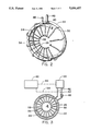
- FIG. 2 is a perspective schematic view of the fuel nozzle and manifold assembly showing the relative positions of the fuel nozzles, manifolds, and supply lines in accordance with one embodiment of the present invention.
- FIG. 3 is a diagrammatic sketch of the fuel injection system made in accordance with one embodiment of the present invention.
- a gas turbine engine 2 of the high bypass type shown in FIG. 1 comprises a fan section 4 a compressor section 6 a combustor section 8 and a turbine section 10.
- the combustor section 8 burns air and fuel to provide high temperature gases to flow into the turbine which then extracts energy from the high temperature gas.
- the high turbine 9 powers the compressor 6 and the low turbine 10 powers the fan 4.
- Surrounding and extending within combustor section 8 is the fuel nozzle and manifold assembly 30 which is more particularly shown in FIG. 2.
- the fuel nozzle and manifold assembly 30 comprises a first fuel manifold 22 and a second fuel manifold 24 which supply fuel to a first and second plurality of fuel nozzles 26 and 28 through a first and second plurality of fuel nozzle lines 32 and 34 respectively.
- FIG. 3 shows a shutoff valve 46 disposed along fuel line 40 and its operation is controlled by a digital electronic computer 42 which also controls the operation of fuel control 44.
- a first control line 52 and a second control line 54 which may be either electronic or electrical, connect the digital electronic computer 42 to the fuel control 44 and shutoff valve 46 respectively as shown in FIG. 1.
- the fuel nozzle and manifold assembly 30 comprises a first fuel manifold 22 which receives its fuel from the fuel control 44 (shown in FIG. 1) through a first fuel line 40.
- a first plurality of fuel nozzles 26 are supported and positioned in the combustor section 8 (shown in FIG. 1), and supplied with fuel from the first fuel manifold 22 by a first plurality of nozzle lines 32.
- a second fuel manifold 24 receives fuel from the fuel control 44 through a second fuel line 42 and supplies fuel to a second plurality of fuel nozzles 28 through a second plurality of nozzle lines 34.
- the second plurality of fuel nozzles 28 are supported and positioned in the combustor section 8 by the second plurality of nozzle lines 34.
- Nozzle lines 32 and 34 may be fuel pipes or structural members with fuel lines contained within as in the present invention.
- FIG. 3 depicts the preferred embodiment in which the first plurality of fuel nozzles 26 are uniformly positioned in an alternating arrangement with the second plurality of fuel nozzles 28.
- all the fuel nozzles 26 and 28 are positioned uniformally and circumferentially with respect to the engine centerline CL.
- the invention is not limited to this particular arrangement and may have arrangements in which every second or third fuel nozzle depends from the first manifold and the rest from the second manifold.
- twenty (20) is an advantageous total number of fuel nozzles wherein there are ten first fuel nozzles 26 connected to the first fuel manifold 22 and ten second fuel nozzles 28 connected to the second fuel manifold 24. This number allows for a even distribution of fuel and temperature in the combustor section 8 during engine operation employing only the second plurality of fuel nozzles 28 while keeping to a minimum the total number of fuel nozzles.
- the fuel nozzle and manifold assembly 30 supplies an atomized fuel and air mixture to the combustor 8 (shown in FIG. 1) in an efficient manner to promote complete combustion.
- Fuel is supplied to the fuel nozzle and manifold assembly 30 by the fuel control 44 through first and second fuel lines 40 and 42 respectively.
- the fuel control 44 meters out the amount of fuel to be burned in combustor section 8 in response to the pilots request or a predetermined schedule.
- the fuel control 44 is controlled by a digital electronic engine computer 42 through a first control line 52.
- a shutoff valve 46 is positioned in first fuel line 40 and is controlled by the digital electronic engine computer 42 through a second control line 54.
- the digital electronic computer monitors various aircraft, flight and engine parameters and calculates other engine parameters or operating conditions. Some of the measured or derived parameters are indicative of the engine's operating condition. Among these parameters are engine fuel flow and combustion air flow which are used to derive a third parameter, fuel to air ratio. Another signal sensed by the engine computer 42 is weight on wheel which indicates the aircraft is on the ground. The weight on wheel signal is used as an override signal to open the valve thereby allowing all twenty fuel nozzles 26 and 28 to operate. This helps to prevent the engine from violating FAA emission regulations relating to invisible engine exhaust emissions.
- the first and second control lines 52 and 54 respectively are indicated by dashed line and may employ either electrical, electronic, or fiber optic connections. Modern aircraft gas turbine engines employ electronic engine controls and this element may also be part of a central aircraft control computer.
- the digital electronic engine control 42 is the means by which the fuel schedule is stored and the schedule's instructions are carried out.
- shutoff valve 46 During most operating conditions the shutoff valve 46 remains in the inactive mode which is open thereby allowing all fuel nozzles 26 and 28 to operate.
- flow to the first plurality of fuel nozzles 26 is shut off or interrupted.
- the valve is activated only during certain operating conditions or in response to a predetermined engine parameter signal.
- the preferred embodiment of the present invention incorporates the derived fuel-to-air ratio as the engine parameter signal.
- Other signals may be used which represent engine operating conditions as well as engine operating parameters.
- Another typical operating condition for which the shutoff valve 46 is activated is descent and in particular idle descent. This condition is signaled to the electronic engine control 42 by the power setting which on modern aircraft is a function of the power lever angle controlled by the pilot.
- the preferred embodiment uses the derived fuel to air ratio parameter.
- the value at which the shutoff valve is activated may be a variable or may be fixed as in the preferred embodiment.
- an overriding weight on wheel signal indicative of the aircraft being on the ground, inactivates the shutoff valve allowing fuel to flow to all fuel nozzles even though one or more other signals indicate the shutoff valve should be activated.
Landscapes
- Engineering & Computer Science (AREA)
- Chemical & Material Sciences (AREA)
- Combustion & Propulsion (AREA)
- Mechanical Engineering (AREA)
- General Engineering & Computer Science (AREA)
Abstract
A dual manifold fuel supply system for the combustor of gas generator in a turbofan engine wherein alternating circumferentially aligned fuel injectors are alternately supplied with fuel by a first or second fuel manifold. Fuel flow to both manifolds are controlled by a fuel control, preferably a full authority digital electronic control, and the second manifold has an off valve interposed between it and the fuel control.
Description
This is a division of application Ser. No. 07/066,300, filed June 25, 1987, now U.S. Pat. No. 4,903,478.
The invention relates to fuel supply systems for high efficiency gas turbine engines for aircraft propulsion and particularly to a new and improved fuel injection system wherein a number of the fuel nozzles may be shutoff in response to power requirements of the gas turbine engine.
The invention relates to fuel supply systems for high efficiency gas turbine engines for aircraft propulsion and particularly to a new and improved dual fuel manifold system and method for operating same wherein each manifold supplies fuel to a portion of the fuel injectors and one of the manifolds has a cutoff valve between it and the fuel control.
Recent improvements in aircraft jet engine technology with respect to fuel efficiency have been too numerous to mention. Improvements in the various components and systems, such as the compressor, turbine, and controls, have yielded significant reductions in the amount of fuel required during typical flight mission cycles. One effect of the reduced fuel requirements is to lower the combustor operating fuel to air ratio to levels approaching the lean stability limit conventionally know as the blowout limit. The reduced fuel requirement exists during steady-state and transient operating conditions of the engine. Under certain flight conditions such as during idle descent on a cold day, a period during which the aircraft is reducing its cruise altitude, the combustor of the gas generating portion of the jet engine may experience fuel starvation at one or more fuel injectors. The result may be severe enough to exceed the blowout limit thereby totally extinguishing the combustion process and stopping the engine's operation. Further complicating the design and operation of these highly efficient engines are FAA emission requirements, in particular those directed to preventing high levels of invisible emissions at idle on the ground. The inventors have discovered a jet engine fuel supply system and method of operation to prevent the aforementioned blowout from occurring. The invention also allows the construction and safe operation of larger more efficient high bypass ratio turbofan and propfan engines of both the ducted and unducted type engines. The invention also improves the exhaust emissions of high bypass ratio gas turbine engines from a pollution standpoint thereby helping to meet stringent FAA emission requirements.
In view of the above mentioned problems with present day high bypass ratio turbofan and propfan jet engines it is a primary object of the invention to prevent aircraft gas turbine engines from exceeding their blowout limit during steady state operation.
One object of the invention is to prevent aircraft gas turbine engines from exceeding their blowout limit during transient operating conditions.
Another object of the invention is to prevent aircraft gas turbine engines from exceeding their blowout limit during adverse operating conditions.
Yet another object of the invention is to allow more efficient aircraft gas turbine engines having high bypass ratios to be designed and built.
A further object of the invention is to improve the safety of fuel efficient high bypass ratio gas turbine engines.
A fuel injection system for use in the combustor section of a gas turbine engine comprising a plurality of fuel nozzles wherein a portion of the fuel nozzles is interruptable in response to a predetermined gas turbine engine parameter or condition. In one form of the invention the engine parameter is the fuel to air ratio and in another form of the invention the engine condition is descent as indicated by the power setting of the gas turbine engine. In another embodiment the invention comprises a first and a second plurality of fuel nozzles which are in fluid supply communication with first and second first fuel manifolds respectively. The manifolds are supplied with fuel by first and second fuel lines, respectively, which in turn are supplied from a fuel control. A shutoff valve is interposed in the first fuel line and is responsive to at least one predetermined gas turbine engine parameter or an engine condition. In yet a further embodiment the valve and fuel control are controlled by a digital electronic computer as described in U.S. Pat. No. 4,137,707.
FIG. 1 is a diagrammatic cross section of a gas turbine engine showing a fuel injection system made in accordance with the present invention.
FIG. 2 is a perspective schematic view of the fuel nozzle and manifold assembly showing the relative positions of the fuel nozzles, manifolds, and supply lines in accordance with one embodiment of the present invention.
FIG. 3 is a diagrammatic sketch of the fuel injection system made in accordance with one embodiment of the present invention.
A gas turbine engine 2 of the high bypass type shown in FIG. 1 comprises a fan section 4 a compressor section 6 a combustor section 8 and a turbine section 10. The combustor section 8 burns air and fuel to provide high temperature gases to flow into the turbine which then extracts energy from the high temperature gas. The high turbine 9 powers the compressor 6 and the low turbine 10 powers the fan 4. Surrounding and extending within combustor section 8 is the fuel nozzle and manifold assembly 30 which is more particularly shown in FIG. 2. The fuel nozzle and manifold assembly 30 comprises a first fuel manifold 22 and a second fuel manifold 24 which supply fuel to a first and second plurality of fuel nozzles 26 and 28 through a first and second plurality of fuel nozzle lines 32 and 34 respectively. Fuel is supplied to manifolds 22 and 24 by first and second fuel lines 40 and 42 respectively and the rate of flow to fuel lines 40 and 42 is controlled by the fuel control 44. FIG. 3 shows a shutoff valve 46 disposed along fuel line 40 and its operation is controlled by a digital electronic computer 42 which also controls the operation of fuel control 44. A first control line 52 and a second control line 54 which may be either electronic or electrical, connect the digital electronic computer 42 to the fuel control 44 and shutoff valve 46 respectively as shown in FIG. 1.
Referring now to FIG. 2, the fuel nozzle and manifold assembly 30 is depicted in order to show the general arrangement and relative positioning of some of the elements. We have found that ring-shaped or annular fuel manifolds are advantageous but the invention is not limited to this particular type of manifold cross section. The fuel nozzle and manifold assembly 30 comprises a first fuel manifold 22 which receives its fuel from the fuel control 44 (shown in FIG. 1) through a first fuel line 40. A first plurality of fuel nozzles 26 are supported and positioned in the combustor section 8 (shown in FIG. 1), and supplied with fuel from the first fuel manifold 22 by a first plurality of nozzle lines 32. A second fuel manifold 24 receives fuel from the fuel control 44 through a second fuel line 42 and supplies fuel to a second plurality of fuel nozzles 28 through a second plurality of nozzle lines 34. The second plurality of fuel nozzles 28 are supported and positioned in the combustor section 8 by the second plurality of nozzle lines 34. Nozzle lines 32 and 34 may be fuel pipes or structural members with fuel lines contained within as in the present invention.
FIG. 3 depicts the preferred embodiment in which the first plurality of fuel nozzles 26 are uniformly positioned in an alternating arrangement with the second plurality of fuel nozzles 28. In the preferred embodiment all the fuel nozzles 26 and 28 are positioned uniformally and circumferentially with respect to the engine centerline CL. However, the invention is not limited to this particular arrangement and may have arrangements in which every second or third fuel nozzle depends from the first manifold and the rest from the second manifold. We have found that twenty (20) is an advantageous total number of fuel nozzles wherein there are ten first fuel nozzles 26 connected to the first fuel manifold 22 and ten second fuel nozzles 28 connected to the second fuel manifold 24. This number allows for a even distribution of fuel and temperature in the combustor section 8 during engine operation employing only the second plurality of fuel nozzles 28 while keeping to a minimum the total number of fuel nozzles.
Referring again to FIG. 3, the invention operates as follows. The fuel nozzle and manifold assembly 30 supplies an atomized fuel and air mixture to the combustor 8 (shown in FIG. 1) in an efficient manner to promote complete combustion. Fuel is supplied to the fuel nozzle and manifold assembly 30 by the fuel control 44 through first and second fuel lines 40 and 42 respectively. The fuel control 44 meters out the amount of fuel to be burned in combustor section 8 in response to the pilots request or a predetermined schedule. The fuel control 44 is controlled by a digital electronic engine computer 42 through a first control line 52. A shutoff valve 46 is positioned in first fuel line 40 and is controlled by the digital electronic engine computer 42 through a second control line 54. The digital electronic computer monitors various aircraft, flight and engine parameters and calculates other engine parameters or operating conditions. Some of the measured or derived parameters are indicative of the engine's operating condition. Among these parameters are engine fuel flow and combustion air flow which are used to derive a third parameter, fuel to air ratio. Another signal sensed by the engine computer 42 is weight on wheel which indicates the aircraft is on the ground. The weight on wheel signal is used as an override signal to open the valve thereby allowing all twenty fuel nozzles 26 and 28 to operate. This helps to prevent the engine from violating FAA emission regulations relating to invisible engine exhaust emissions.
The first and second control lines 52 and 54 respectively are indicated by dashed line and may employ either electrical, electronic, or fiber optic connections. Modern aircraft gas turbine engines employ electronic engine controls and this element may also be part of a central aircraft control computer. The digital electronic engine control 42 is the means by which the fuel schedule is stored and the schedule's instructions are carried out.
During most operating conditions the shutoff valve 46 remains in the inactive mode which is open thereby allowing all fuel nozzles 26 and 28 to operate. When shutoff valve 46 is activated, flow to the first plurality of fuel nozzles 26 is shut off or interrupted. The valve is activated only during certain operating conditions or in response to a predetermined engine parameter signal. The preferred embodiment of the present invention incorporates the derived fuel-to-air ratio as the engine parameter signal. Other signals may be used which represent engine operating conditions as well as engine operating parameters. Another typical operating condition for which the shutoff valve 46 is activated is descent and in particular idle descent. This condition is signaled to the electronic engine control 42 by the power setting which on modern aircraft is a function of the power lever angle controlled by the pilot. The preferred embodiment uses the derived fuel to air ratio parameter. The value at which the shutoff valve is activated may be a variable or may be fixed as in the preferred embodiment. In order to prevent unduly high emission levels an overriding weight on wheel signal, indicative of the aircraft being on the ground, inactivates the shutoff valve allowing fuel to flow to all fuel nozzles even though one or more other signals indicate the shutoff valve should be activated.
It is to be understood that this invention is not limited to the particular embodiment disclosed, and it is intended to cover all modifications coming within the scope of this invention as claimed.
Claims (7)
1. A fuel injection system for use in the combustor section of a gas turbine engine said fuel injection system comprising:
a plurality of generally downstream facing fuel nozzles wherein a portion of said fuel nozzles are connected to a shutoff valve means which is interruptible, a means for interrupting said valve means in response to a control signal, and
a means for generating said control signal based on the gas turbine engine fuel to air ratio and an overriding weight on wheels signal.
2. A fuel injection system for use in the combustor section of a gas turbine engine said fuel injection system comprising:
first and second fuel lines,
first and second pluralities of generally downstream facing fuel nozzles in fluid supply communication with said first and second fuel lines respectively,
a shutoff valve interposed in said first fuel line, a means for shutting on and off said valve in response to a control signal; and
a means for generating said control signal based upon the gas turbine engine fuel to air ratio and an overriding weight on wheels signal.
3. A fuel injection system as set forth in claim 2 comprising: first and second fuel manifolds disposed between said first and second fuel lines and said first and second pluralities of fuel nozzles respectively.
4. A fuel injection system as set forth in claim 3 wherein: said first and second pluralities of fuel nozzles are arranged in a generally circular and alternating pattern.
5. A fuel injection system as set forth in claim 4 including:
a fuel control in supply communication with said first and second fuel lines.
6. A fuel injection system as set forth in claim 5 wherein said means for generating said control signal is an electronic engine control which controls said shutoff valve and said fuel control.
7. A fuel injection system as set forth in claim 6 wherein:
said electronic engine control is a digital electronic engine control.
Priority Applications (1)
| Application Number | Priority Date | Filing Date | Title |
|---|---|---|---|
| US07/424,037 US5036657A (en) | 1987-06-25 | 1989-10-19 | Dual manifold fuel system |
Applications Claiming Priority (2)
| Application Number | Priority Date | Filing Date | Title |
|---|---|---|---|
| US07/066,300 US4903478A (en) | 1987-06-25 | 1987-06-25 | Dual manifold fuel system |
| US07/424,037 US5036657A (en) | 1987-06-25 | 1989-10-19 | Dual manifold fuel system |
Related Parent Applications (1)
| Application Number | Title | Priority Date | Filing Date |
|---|---|---|---|
| US07/066,300 Division US4903478A (en) | 1987-06-25 | 1987-06-25 | Dual manifold fuel system |
Publications (1)
| Publication Number | Publication Date |
|---|---|
| US5036657A true US5036657A (en) | 1991-08-06 |
Family
ID=26746589
Family Applications (1)
| Application Number | Title | Priority Date | Filing Date |
|---|---|---|---|
| US07/424,037 Expired - Lifetime US5036657A (en) | 1987-06-25 | 1989-10-19 | Dual manifold fuel system |
Country Status (1)
| Country | Link |
|---|---|
| US (1) | US5036657A (en) |
Cited By (69)
| Publication number | Priority date | Publication date | Assignee | Title |
|---|---|---|---|---|
| US5211005A (en) * | 1992-04-16 | 1993-05-18 | Avco Corporation | High density fuel injection manifold |
| US5231833A (en) * | 1991-01-18 | 1993-08-03 | General Electric Company | Gas turbine engine fuel manifold |
| US5321949A (en) * | 1991-07-12 | 1994-06-21 | General Electric Company | Staged fuel delivery system with secondary distribution valve |
| US5331814A (en) * | 1992-08-05 | 1994-07-26 | Societe Nationale D'etude Et De Construction De Moteurs D'aviation (S.N.E.C.M.A.) | Gas turbine combustion chamber with multiple fuel injector arrays |
| US5339636A (en) * | 1992-12-04 | 1994-08-23 | United Technologies Corporation | Fuel splitter valve assembly for gas turbine |
| US5402634A (en) * | 1993-10-22 | 1995-04-04 | United Technologies Corporation | Fuel supply system for a staged combustor |
| US5406799A (en) * | 1992-06-12 | 1995-04-18 | United Technologies Corporation | Combustion chamber |
| DE19524213A1 (en) * | 1995-07-03 | 1997-01-09 | Abb Management Ag | Fuel supply for gas turbines with an annular combustion chamber |
| US5598698A (en) * | 1993-12-22 | 1997-02-04 | United Technologies Corporation | Fuel control system for a staged combustor |
| US5901555A (en) * | 1996-02-05 | 1999-05-11 | Mitsubishi Heavy Industries, Ltd. | Gas turbine combustor having multiple burner groups and independently operable pilot fuel injection systems |
| US6058710A (en) * | 1995-03-08 | 2000-05-09 | Bmw Rolls-Royce Gmbh | Axially staged annular combustion chamber of a gas turbine |
| EP1098140A1 (en) * | 1999-11-05 | 2001-05-09 | General Electric Company | Methods and apparatus for fuel nozzle staging for gas turbine engines |
| US6405524B1 (en) * | 2000-08-16 | 2002-06-18 | General Electric Company | Apparatus for decreasing gas turbine combustor emissions |
| US20020189259A1 (en) * | 1999-04-01 | 2002-12-19 | Peter Laing | Fuel manifold block and ring with macrolaminate layers |
| EP1367325A1 (en) * | 2002-05-22 | 2003-12-03 | Hamilton Sundstrand Corporation | Fuel supply control for a gas turbine including multiple solenoid valves |
| US6666029B2 (en) | 2001-12-06 | 2003-12-23 | Siemens Westinghouse Power Corporation | Gas turbine pilot burner and method |
| US20040040306A1 (en) * | 2002-08-30 | 2004-03-04 | Prociw Lev Alexander | Nested channel ducts for nozzle construction and the like |
| US20040144098A1 (en) * | 2000-02-24 | 2004-07-29 | Willis Jeffrey W. | Multi-stage multi-plane combustion method for a gas turbine engine |
| US20040221582A1 (en) * | 2003-05-08 | 2004-11-11 | Howell Stephen John | Sector staging combustor |
| US6868676B1 (en) * | 2002-12-20 | 2005-03-22 | General Electric Company | Turbine containing system and an injector therefor |
| US20050160739A1 (en) * | 2004-01-19 | 2005-07-28 | Jan Cerny | Method for operating a gas turbine combustion chamber |
| US20050188699A1 (en) * | 2004-02-27 | 2005-09-01 | Pratt & Whitney Canada Corp. | Apparatus for fuel transport and the like |
| US20050241318A1 (en) * | 2004-04-29 | 2005-11-03 | Honeywell International Inc. | Multiple electric fuel metering systems for gas turbine applications |
| US20060156733A1 (en) * | 2005-01-14 | 2006-07-20 | Pratt & Whitney Canada Corp. | Integral heater for fuel conveying member |
| US20060156731A1 (en) * | 2005-01-18 | 2006-07-20 | Pratt & Whitney Canada Corp. | Heat shield for a fuel manifold and method |
| US20060218925A1 (en) * | 2005-04-01 | 2006-10-05 | Prociw Lev A | Internal fuel manifold with airblast nozzles |
| US20060218926A1 (en) * | 2005-04-01 | 2006-10-05 | Pratt & Whitney Canada Corp. | Fuel conveying member with heat pipe |
| US20060277913A1 (en) * | 2005-06-14 | 2006-12-14 | Pratt & Whitney Canada Corp. | Internally mounted fuel manifold with support pins |
| EP1358401A4 (en) * | 2001-02-06 | 2007-08-22 | United Technologies Corp | Bulkhead for dual fuel industrial and aeroengine gas turbines |
| US20070204621A1 (en) * | 2006-03-03 | 2007-09-06 | Pratt & Whitney Canada Corp. | Fuel conveying member with side-brazed sealing members |
| US20070204622A1 (en) * | 2006-03-03 | 2007-09-06 | Pratt & Whitney Canada Corp. | Internal fuel manifold with turned channel having a variable cross-sectional area |
| US20070234724A1 (en) * | 2005-09-08 | 2007-10-11 | Pratt & Whitney Canada Corp. | Redundant fuel manifold sealing arrangement |
| US20070234727A1 (en) * | 2006-03-31 | 2007-10-11 | Pratt & Whitney Canada Corp. | Gas turbine engine combustor with improved cooling |
| US20080016870A1 (en) * | 2006-07-20 | 2008-01-24 | Pratt & Whitney Canada Corp. | Fuel conveying member for a gas turbine engine |
| US20080047274A1 (en) * | 2006-08-22 | 2008-02-28 | Jason Fish | Optimized internal manifold heat shield attachment |
| US20080053096A1 (en) * | 2006-08-31 | 2008-03-06 | Pratt & Whitney Canada Corp. | Fuel injection system and method of assembly |
| US20080072599A1 (en) * | 2006-09-26 | 2008-03-27 | Oleg Morenko | Heat shield for a fuel manifold |
| US20080072598A1 (en) * | 2006-09-22 | 2008-03-27 | Jason Fish | Heat shield with stress relieving feature |
| US20080083225A1 (en) * | 2006-10-04 | 2008-04-10 | Jason Fish | Reduced stress internal manifold heat shield attachment |
| US20080083223A1 (en) * | 2006-10-04 | 2008-04-10 | Lev Alexander Prociw | Multi-channel fuel manifold |
| US20080307791A1 (en) * | 2007-06-14 | 2008-12-18 | Frank Shum | Fuel nozzle providing shaped fuel spray |
| US20080308654A1 (en) * | 2007-06-14 | 2008-12-18 | Pelletier Robert R | Fuel injector nozzle with macrolaminate fuel swirler |
| US20090072051A1 (en) * | 2007-05-16 | 2009-03-19 | Jason Fish | Redundant mounting system for an internal fuel manifold |
| US20090126368A1 (en) * | 2006-08-31 | 2009-05-21 | Patel Bhawan B | Fuel injection system for a gas turbine engine |
| US20090145105A1 (en) * | 2004-12-01 | 2009-06-11 | Suciu Gabriel L | Remote engine fuel control and electronic engine control for turbine engine |
| US20100058770A1 (en) * | 2008-09-08 | 2010-03-11 | Siemens Power Generation, Inc. | Method and System for Controlling Fuel to a Dual Stage Nozzle |
| US20100064692A1 (en) * | 2007-03-15 | 2010-03-18 | Kam-Kei Lam | Burner fuel staging |
| US20100077758A1 (en) * | 2006-09-18 | 2010-04-01 | Nagaraja Rudrapatna | Internal fuel manifold having temperature reduction feature |
| US20100229555A1 (en) * | 2006-03-03 | 2010-09-16 | Pratt & Whitney Canada Corp. | Fuel manifold with reduced losses |
| US20110030375A1 (en) * | 2009-08-04 | 2011-02-10 | General Electric Company | Aerodynamic pylon fuel injector system for combustors |
| US20110154824A1 (en) * | 2009-12-31 | 2011-06-30 | General Electric Company | Frequency-tunable bracketless fluid manifold |
| US20120174591A1 (en) * | 2009-09-24 | 2012-07-12 | Matthias Hase | Fuel Line System, Method for Operating of a Gas Turbine, and a Method for Purging the Fuel Line System of a Gas Turbine |
| US8353166B2 (en) | 2006-08-18 | 2013-01-15 | Pratt & Whitney Canada Corp. | Gas turbine combustor and fuel manifold mounting arrangement |
| US20140007579A1 (en) * | 2012-07-06 | 2014-01-09 | Hamilton Sundstrand Corporation | Non-symmetric arrangement of fuel nozzles in a combustor |
| US20140061327A1 (en) * | 2012-08-31 | 2014-03-06 | General Electric Company | System and method for staging fuel to a combustor |
| WO2014052221A1 (en) * | 2012-09-28 | 2014-04-03 | United Technologies Corporation | Fuel distribution within a gas turbine engine combustor |
| US20150176495A1 (en) * | 2013-12-20 | 2015-06-25 | Pratt & Whitney Canada Crop. | Fluid manifold for gas turbine engine and method for delivering fuel to a combustor using same |
| EP3009640A1 (en) * | 2014-10-17 | 2016-04-20 | United Technologies Corporation | Fuel system for tone control and operability |
| US9447733B2 (en) | 2013-03-14 | 2016-09-20 | Pratt & Whitney Canada Corp. | Gas turbine engine fuel system with ecology valve |
| US20160281993A1 (en) * | 2015-03-27 | 2016-09-29 | Ansaldo Energia Switzerland AG | Integrated dual fuel delivery system |
| US9957891B2 (en) | 2011-09-09 | 2018-05-01 | General Electric Company | Fuel manifold cooling flow recirculation |
| US10240533B2 (en) | 2011-11-22 | 2019-03-26 | United Technologies Corporation | Fuel distribution within a gas turbine engine combustor |
| US20190113233A1 (en) * | 2017-10-18 | 2019-04-18 | Rolls-Royce North American Technologies Inc. | Fuel injection assembly for gas turbine engine |
| US10428738B2 (en) * | 2016-12-14 | 2019-10-01 | Solar Turbines Incorporated | Start biased liquid fuel manifold for a gas turbine engine |
| US10526972B2 (en) | 2016-12-07 | 2020-01-07 | Rolls-Royce Corporation | Segmented fuel delivery system |
| US10605171B2 (en) * | 2018-04-10 | 2020-03-31 | Delavan Inc. | Fuel nozzle manifold systems for turbomachines |
| RU2779807C1 (en) * | 2022-01-12 | 2022-09-13 | Публичное акционерное общество "ОДК - Уфимское моторостроительное производственное объединение" (ПАО "ОДК-УМПО") | Method for regulating fuel supply to gas turbine engine combustion chamber |
| US20250264063A1 (en) * | 2024-02-19 | 2025-08-21 | Rolls-Royce Plc | Aircraft comprising a gas turbine engine having primary and secondary fuel-injectors |
| US20250377103A1 (en) * | 2024-06-10 | 2025-12-11 | Rolls-Royce Plc | Engine Core Size |
Citations (24)
| Publication number | Priority date | Publication date | Assignee | Title |
|---|---|---|---|---|
| GB577062A (en) * | 1944-10-30 | 1946-05-02 | Dehavilland Aircraft | Improvements in or relating to turbo-compressor propulsive apparatus |
| US2617478A (en) * | 1949-08-29 | 1952-11-11 | Westinghouse Electric Corp | Selective control of fuel nozzle manifolds to vary discharge flow capacity |
| US2846845A (en) * | 1953-06-24 | 1958-08-12 | Gen Electric | Fuel drainage system for plural manifolds |
| US2927425A (en) * | 1956-11-07 | 1960-03-08 | Bendix Aviat Corp | Flow control apparatus |
| US2951341A (en) * | 1956-09-19 | 1960-09-06 | Westinghouse Electric Corp | Fuel injection system for an aircraft engine |
| US3056259A (en) * | 1957-01-28 | 1962-10-02 | Rolls Royce | Engine liquid fuel supply system |
| US3158998A (en) * | 1962-09-04 | 1964-12-01 | Gen Motors Corp | Automatic control for afterburner manifold utilizing two fluids |
| US3468333A (en) * | 1967-05-01 | 1969-09-23 | Lucas Industries Ltd | Fuel system for a gas turbine engine |
| US3698186A (en) * | 1970-12-24 | 1972-10-17 | United Aircraft Corp | Afterburner combustion apparatus |
| US3925002A (en) * | 1974-11-11 | 1975-12-09 | Gen Motors Corp | Air preheating combustion apparatus |
| US4027473A (en) * | 1976-03-05 | 1977-06-07 | United Technologies Corporation | Fuel distribution valve |
| US4062183A (en) * | 1975-06-10 | 1977-12-13 | Rolls-Royce Limited | Fuel supply system for a gas turbine engine |
| GB1504348A (en) * | 1975-09-17 | 1978-03-22 | Polyakov A | Fuel distribution arrangement of a gas turbine engine |
| GB2041085A (en) * | 1978-12-20 | 1980-09-03 | Lucas Industries Ltd | Fuel supply apparatus for gas turbine engine |
| US4305255A (en) * | 1978-11-20 | 1981-12-15 | Rolls-Royce Limited | Combined pilot and main burner |
| US4313167A (en) * | 1979-07-27 | 1982-01-26 | General Electric Company | Thrust control system for a gas turbine engine |
| US4312185A (en) * | 1980-02-19 | 1982-01-26 | General Electric Company | Low profile fuel injection system |
| US4337616A (en) * | 1980-04-14 | 1982-07-06 | General Motors Corporation | Fuel air ratio controlled fuel splitter |
| GB2125110A (en) * | 1982-08-11 | 1984-02-29 | United Technologies Corp | Gas turbine augmentor fuel control system |
| US4499735A (en) * | 1982-03-23 | 1985-02-19 | The United States Of America As Represented By The Secretary Of The Air Force | Segmented zoned fuel injection system for use with a combustor |
| US4541237A (en) * | 1983-10-17 | 1985-09-17 | Avco Corporation | Sub-idle speed control apparatus for an airplane turbine engine |
| JPS61132729A (en) * | 1984-11-30 | 1986-06-20 | Toshiba Corp | Gas turbine combustion control equipment |
| US4603548A (en) * | 1983-09-08 | 1986-08-05 | Hitachi, Ltd. | Method of supplying fuel into gas turbine combustor |
| US4716719A (en) * | 1985-04-17 | 1988-01-05 | Hitachi, Ltd. | Method of and apparatus for controlling fuel of gas turbine |
-
1989
- 1989-10-19 US US07/424,037 patent/US5036657A/en not_active Expired - Lifetime
Patent Citations (24)
| Publication number | Priority date | Publication date | Assignee | Title |
|---|---|---|---|---|
| GB577062A (en) * | 1944-10-30 | 1946-05-02 | Dehavilland Aircraft | Improvements in or relating to turbo-compressor propulsive apparatus |
| US2617478A (en) * | 1949-08-29 | 1952-11-11 | Westinghouse Electric Corp | Selective control of fuel nozzle manifolds to vary discharge flow capacity |
| US2846845A (en) * | 1953-06-24 | 1958-08-12 | Gen Electric | Fuel drainage system for plural manifolds |
| US2951341A (en) * | 1956-09-19 | 1960-09-06 | Westinghouse Electric Corp | Fuel injection system for an aircraft engine |
| US2927425A (en) * | 1956-11-07 | 1960-03-08 | Bendix Aviat Corp | Flow control apparatus |
| US3056259A (en) * | 1957-01-28 | 1962-10-02 | Rolls Royce | Engine liquid fuel supply system |
| US3158998A (en) * | 1962-09-04 | 1964-12-01 | Gen Motors Corp | Automatic control for afterburner manifold utilizing two fluids |
| US3468333A (en) * | 1967-05-01 | 1969-09-23 | Lucas Industries Ltd | Fuel system for a gas turbine engine |
| US3698186A (en) * | 1970-12-24 | 1972-10-17 | United Aircraft Corp | Afterburner combustion apparatus |
| US3925002A (en) * | 1974-11-11 | 1975-12-09 | Gen Motors Corp | Air preheating combustion apparatus |
| US4062183A (en) * | 1975-06-10 | 1977-12-13 | Rolls-Royce Limited | Fuel supply system for a gas turbine engine |
| GB1504348A (en) * | 1975-09-17 | 1978-03-22 | Polyakov A | Fuel distribution arrangement of a gas turbine engine |
| US4027473A (en) * | 1976-03-05 | 1977-06-07 | United Technologies Corporation | Fuel distribution valve |
| US4305255A (en) * | 1978-11-20 | 1981-12-15 | Rolls-Royce Limited | Combined pilot and main burner |
| GB2041085A (en) * | 1978-12-20 | 1980-09-03 | Lucas Industries Ltd | Fuel supply apparatus for gas turbine engine |
| US4313167A (en) * | 1979-07-27 | 1982-01-26 | General Electric Company | Thrust control system for a gas turbine engine |
| US4312185A (en) * | 1980-02-19 | 1982-01-26 | General Electric Company | Low profile fuel injection system |
| US4337616A (en) * | 1980-04-14 | 1982-07-06 | General Motors Corporation | Fuel air ratio controlled fuel splitter |
| US4499735A (en) * | 1982-03-23 | 1985-02-19 | The United States Of America As Represented By The Secretary Of The Air Force | Segmented zoned fuel injection system for use with a combustor |
| GB2125110A (en) * | 1982-08-11 | 1984-02-29 | United Technologies Corp | Gas turbine augmentor fuel control system |
| US4603548A (en) * | 1983-09-08 | 1986-08-05 | Hitachi, Ltd. | Method of supplying fuel into gas turbine combustor |
| US4541237A (en) * | 1983-10-17 | 1985-09-17 | Avco Corporation | Sub-idle speed control apparatus for an airplane turbine engine |
| JPS61132729A (en) * | 1984-11-30 | 1986-06-20 | Toshiba Corp | Gas turbine combustion control equipment |
| US4716719A (en) * | 1985-04-17 | 1988-01-05 | Hitachi, Ltd. | Method of and apparatus for controlling fuel of gas turbine |
Cited By (122)
| Publication number | Priority date | Publication date | Assignee | Title |
|---|---|---|---|---|
| US5231833A (en) * | 1991-01-18 | 1993-08-03 | General Electric Company | Gas turbine engine fuel manifold |
| US5321949A (en) * | 1991-07-12 | 1994-06-21 | General Electric Company | Staged fuel delivery system with secondary distribution valve |
| US5211005A (en) * | 1992-04-16 | 1993-05-18 | Avco Corporation | High density fuel injection manifold |
| US5406799A (en) * | 1992-06-12 | 1995-04-18 | United Technologies Corporation | Combustion chamber |
| US5331814A (en) * | 1992-08-05 | 1994-07-26 | Societe Nationale D'etude Et De Construction De Moteurs D'aviation (S.N.E.C.M.A.) | Gas turbine combustion chamber with multiple fuel injector arrays |
| US5339636A (en) * | 1992-12-04 | 1994-08-23 | United Technologies Corporation | Fuel splitter valve assembly for gas turbine |
| US5402634A (en) * | 1993-10-22 | 1995-04-04 | United Technologies Corporation | Fuel supply system for a staged combustor |
| US5598698A (en) * | 1993-12-22 | 1997-02-04 | United Technologies Corporation | Fuel control system for a staged combustor |
| US5916126A (en) * | 1993-12-22 | 1999-06-29 | United Technologies Corporation | Starting fuel control system for a staged combustor |
| US6058710A (en) * | 1995-03-08 | 2000-05-09 | Bmw Rolls-Royce Gmbh | Axially staged annular combustion chamber of a gas turbine |
| DE19524213A1 (en) * | 1995-07-03 | 1997-01-09 | Abb Management Ag | Fuel supply for gas turbines with an annular combustion chamber |
| US5765366A (en) * | 1995-07-03 | 1998-06-16 | Asea Brown Boveri Ag | Fuel feed for gas turbines having an annular combustion chamber |
| US5901555A (en) * | 1996-02-05 | 1999-05-11 | Mitsubishi Heavy Industries, Ltd. | Gas turbine combustor having multiple burner groups and independently operable pilot fuel injection systems |
| US20020189259A1 (en) * | 1999-04-01 | 2002-12-19 | Peter Laing | Fuel manifold block and ring with macrolaminate layers |
| US6711898B2 (en) * | 1999-04-01 | 2004-03-30 | Parker-Hannifin Corporation | Fuel manifold block and ring with macrolaminate layers |
| EP1098140A1 (en) * | 1999-11-05 | 2001-05-09 | General Electric Company | Methods and apparatus for fuel nozzle staging for gas turbine engines |
| US6389800B2 (en) | 1999-11-05 | 2002-05-21 | General Electric Company | Apparatus for fuel nozzle staging for gas turbine engines |
| US6393823B1 (en) | 1999-11-05 | 2002-05-28 | General Electric Company | Methods for fuel nozzle staging for gas turbine engines |
| US20040144098A1 (en) * | 2000-02-24 | 2004-07-29 | Willis Jeffrey W. | Multi-stage multi-plane combustion method for a gas turbine engine |
| US6405524B1 (en) * | 2000-08-16 | 2002-06-18 | General Electric Company | Apparatus for decreasing gas turbine combustor emissions |
| US6681556B2 (en) * | 2000-08-16 | 2004-01-27 | General Electric Company | Apparatus for decreasing combustor emissions |
| EP1358401A4 (en) * | 2001-02-06 | 2007-08-22 | United Technologies Corp | Bulkhead for dual fuel industrial and aeroengine gas turbines |
| US6666029B2 (en) | 2001-12-06 | 2003-12-23 | Siemens Westinghouse Power Corporation | Gas turbine pilot burner and method |
| US6786049B2 (en) | 2002-05-22 | 2004-09-07 | Hamilton Sundstrand | Fuel supply control for a gas turbine including multiple solenoid valves |
| EP1367325A1 (en) * | 2002-05-22 | 2003-12-03 | Hamilton Sundstrand Corporation | Fuel supply control for a gas turbine including multiple solenoid valves |
| US8074452B2 (en) | 2002-08-30 | 2011-12-13 | Pratt & Whitney Canada Corp. | Nested channel ducts for nozzle construction and the like |
| US20040040306A1 (en) * | 2002-08-30 | 2004-03-04 | Prociw Lev Alexander | Nested channel ducts for nozzle construction and the like |
| US20090320479A1 (en) * | 2002-08-30 | 2009-12-31 | Lev Alexander Prociw | Nested channel ducts for nozzle construction and the like |
| US7028484B2 (en) | 2002-08-30 | 2006-04-18 | Pratt & Whitney Canada Corp. | Nested channel ducts for nozzle construction and the like |
| US6868676B1 (en) * | 2002-12-20 | 2005-03-22 | General Electric Company | Turbine containing system and an injector therefor |
| US20040221582A1 (en) * | 2003-05-08 | 2004-11-11 | Howell Stephen John | Sector staging combustor |
| US6968699B2 (en) * | 2003-05-08 | 2005-11-29 | General Electric Company | Sector staging combustor |
| US20050160739A1 (en) * | 2004-01-19 | 2005-07-28 | Jan Cerny | Method for operating a gas turbine combustion chamber |
| US7434404B2 (en) * | 2004-01-19 | 2008-10-14 | Alstom Technology Ltd. | Method for operating a gas turbine combustion chamber including a plurality of burners arranged in groups |
| US7654088B2 (en) * | 2004-02-27 | 2010-02-02 | Pratt & Whitney Canada Corp. | Dual conduit fuel manifold for gas turbine engine |
| US20050188699A1 (en) * | 2004-02-27 | 2005-09-01 | Pratt & Whitney Canada Corp. | Apparatus for fuel transport and the like |
| US20050241318A1 (en) * | 2004-04-29 | 2005-11-03 | Honeywell International Inc. | Multiple electric fuel metering systems for gas turbine applications |
| US7197879B2 (en) | 2004-04-29 | 2007-04-03 | Honeywell International, Inc. | Multiple electric fuel metering systems for gas turbine applications |
| US20090145105A1 (en) * | 2004-12-01 | 2009-06-11 | Suciu Gabriel L | Remote engine fuel control and electronic engine control for turbine engine |
| US8276387B2 (en) * | 2005-01-14 | 2012-10-02 | Pratt & Whitney Canada Corp. | Gas turbine engine fuel conveying member |
| US20110173982A1 (en) * | 2005-01-14 | 2011-07-21 | Lev Alexander Prociw | Gas turbine engine fuel conveying member |
| US20110120142A1 (en) * | 2005-01-14 | 2011-05-26 | Lev Alexander Prociw | Gas turbine engine fuel conveying member |
| US7937926B2 (en) | 2005-01-14 | 2011-05-10 | Pratt & Whitney Canada Corp. | Integral heater for fuel conveying member |
| US20060156733A1 (en) * | 2005-01-14 | 2006-07-20 | Pratt & Whitney Canada Corp. | Integral heater for fuel conveying member |
| US20090084108A1 (en) * | 2005-01-14 | 2009-04-02 | Lev Alexander Prociw | Integral heater for fuel conveying member |
| US7565807B2 (en) | 2005-01-18 | 2009-07-28 | Pratt & Whitney Canada Corp. | Heat shield for a fuel manifold and method |
| US20060156731A1 (en) * | 2005-01-18 | 2006-07-20 | Pratt & Whitney Canada Corp. | Heat shield for a fuel manifold and method |
| US20060218926A1 (en) * | 2005-04-01 | 2006-10-05 | Pratt & Whitney Canada Corp. | Fuel conveying member with heat pipe |
| US20060218925A1 (en) * | 2005-04-01 | 2006-10-05 | Prociw Lev A | Internal fuel manifold with airblast nozzles |
| US7533531B2 (en) | 2005-04-01 | 2009-05-19 | Pratt & Whitney Canada Corp. | Internal fuel manifold with airblast nozzles |
| US7530231B2 (en) | 2005-04-01 | 2009-05-12 | Pratt & Whitney Canada Corp. | Fuel conveying member with heat pipe |
| US7540157B2 (en) | 2005-06-14 | 2009-06-02 | Pratt & Whitney Canada Corp. | Internally mounted fuel manifold with support pins |
| US8171739B2 (en) | 2005-06-14 | 2012-05-08 | Pratt & Whitney Canada Corp. | Internally mounted fuel manifold with support pins |
| US20060277913A1 (en) * | 2005-06-14 | 2006-12-14 | Pratt & Whitney Canada Corp. | Internally mounted fuel manifold with support pins |
| US7559201B2 (en) | 2005-09-08 | 2009-07-14 | Pratt & Whitney Canada Corp. | Redundant fuel manifold sealing arrangement |
| US20070234724A1 (en) * | 2005-09-08 | 2007-10-11 | Pratt & Whitney Canada Corp. | Redundant fuel manifold sealing arrangement |
| US7854120B2 (en) | 2006-03-03 | 2010-12-21 | Pratt & Whitney Canada Corp. | Fuel manifold with reduced losses |
| US7942002B2 (en) | 2006-03-03 | 2011-05-17 | Pratt & Whitney Canada Corp. | Fuel conveying member with side-brazed sealing members |
| US20070204621A1 (en) * | 2006-03-03 | 2007-09-06 | Pratt & Whitney Canada Corp. | Fuel conveying member with side-brazed sealing members |
| US20070204622A1 (en) * | 2006-03-03 | 2007-09-06 | Pratt & Whitney Canada Corp. | Internal fuel manifold with turned channel having a variable cross-sectional area |
| US20100229555A1 (en) * | 2006-03-03 | 2010-09-16 | Pratt & Whitney Canada Corp. | Fuel manifold with reduced losses |
| US7607226B2 (en) | 2006-03-03 | 2009-10-27 | Pratt & Whitney Canada Corp. | Internal fuel manifold with turned channel having a variable cross-sectional area |
| US20070234727A1 (en) * | 2006-03-31 | 2007-10-11 | Pratt & Whitney Canada Corp. | Gas turbine engine combustor with improved cooling |
| US7624577B2 (en) | 2006-03-31 | 2009-12-01 | Pratt & Whitney Canada Corp. | Gas turbine engine combustor with improved cooling |
| US20080016870A1 (en) * | 2006-07-20 | 2008-01-24 | Pratt & Whitney Canada Corp. | Fuel conveying member for a gas turbine engine |
| US8096130B2 (en) | 2006-07-20 | 2012-01-17 | Pratt & Whitney Canada Corp. | Fuel conveying member for a gas turbine engine |
| US8353166B2 (en) | 2006-08-18 | 2013-01-15 | Pratt & Whitney Canada Corp. | Gas turbine combustor and fuel manifold mounting arrangement |
| US7765808B2 (en) | 2006-08-22 | 2010-08-03 | Pratt & Whitney Canada Corp. | Optimized internal manifold heat shield attachment |
| US20080047274A1 (en) * | 2006-08-22 | 2008-02-28 | Jason Fish | Optimized internal manifold heat shield attachment |
| US8033113B2 (en) | 2006-08-31 | 2011-10-11 | Pratt & Whitney Canada Corp. | Fuel injection system for a gas turbine engine |
| US20090126368A1 (en) * | 2006-08-31 | 2009-05-21 | Patel Bhawan B | Fuel injection system for a gas turbine engine |
| US20080053096A1 (en) * | 2006-08-31 | 2008-03-06 | Pratt & Whitney Canada Corp. | Fuel injection system and method of assembly |
| US7703289B2 (en) | 2006-09-18 | 2010-04-27 | Pratt & Whitney Canada Corp. | Internal fuel manifold having temperature reduction feature |
| US20100077758A1 (en) * | 2006-09-18 | 2010-04-01 | Nagaraja Rudrapatna | Internal fuel manifold having temperature reduction feature |
| US7775047B2 (en) | 2006-09-22 | 2010-08-17 | Pratt & Whitney Canada Corp. | Heat shield with stress relieving feature |
| US20080072598A1 (en) * | 2006-09-22 | 2008-03-27 | Jason Fish | Heat shield with stress relieving feature |
| US7559142B2 (en) | 2006-09-26 | 2009-07-14 | Pratt & Whitney Canada Corp. | Method of manufacturing a heat shield for a fuel manifold |
| US20080072599A1 (en) * | 2006-09-26 | 2008-03-27 | Oleg Morenko | Heat shield for a fuel manifold |
| US7926286B2 (en) | 2006-09-26 | 2011-04-19 | Pratt & Whitney Canada Corp. | Heat shield for a fuel manifold |
| US20080078080A1 (en) * | 2006-09-26 | 2008-04-03 | Patel Bhawan B | Method of manufacturing a heat shield for a fuel manifold |
| US7716933B2 (en) | 2006-10-04 | 2010-05-18 | Pratt & Whitney Canada Corp. | Multi-channel fuel manifold |
| US20080083225A1 (en) * | 2006-10-04 | 2008-04-10 | Jason Fish | Reduced stress internal manifold heat shield attachment |
| US8572976B2 (en) | 2006-10-04 | 2013-11-05 | Pratt & Whitney Canada Corp. | Reduced stress internal manifold heat shield attachment |
| US20080083223A1 (en) * | 2006-10-04 | 2008-04-10 | Lev Alexander Prociw | Multi-channel fuel manifold |
| US20100064692A1 (en) * | 2007-03-15 | 2010-03-18 | Kam-Kei Lam | Burner fuel staging |
| US8484979B2 (en) * | 2007-03-15 | 2013-07-16 | Siemens Aktiengesellschaft | Burner fuel staging |
| US7856825B2 (en) | 2007-05-16 | 2010-12-28 | Pratt & Whitney Canada Corp. | Redundant mounting system for an internal fuel manifold |
| US20090072051A1 (en) * | 2007-05-16 | 2009-03-19 | Jason Fish | Redundant mounting system for an internal fuel manifold |
| US8146365B2 (en) | 2007-06-14 | 2012-04-03 | Pratt & Whitney Canada Corp. | Fuel nozzle providing shaped fuel spray |
| US8020384B2 (en) * | 2007-06-14 | 2011-09-20 | Parker-Hannifin Corporation | Fuel injector nozzle with macrolaminate fuel swirler |
| US20080307791A1 (en) * | 2007-06-14 | 2008-12-18 | Frank Shum | Fuel nozzle providing shaped fuel spray |
| US20080308654A1 (en) * | 2007-06-14 | 2008-12-18 | Pelletier Robert R | Fuel injector nozzle with macrolaminate fuel swirler |
| US20100058770A1 (en) * | 2008-09-08 | 2010-03-11 | Siemens Power Generation, Inc. | Method and System for Controlling Fuel to a Dual Stage Nozzle |
| US8820087B2 (en) | 2008-09-08 | 2014-09-02 | Siemens Energy, Inc. | Method and system for controlling fuel to a dual stage nozzle |
| US20110030375A1 (en) * | 2009-08-04 | 2011-02-10 | General Electric Company | Aerodynamic pylon fuel injector system for combustors |
| US8763400B2 (en) * | 2009-08-04 | 2014-07-01 | General Electric Company | Aerodynamic pylon fuel injector system for combustors |
| US20120174591A1 (en) * | 2009-09-24 | 2012-07-12 | Matthias Hase | Fuel Line System, Method for Operating of a Gas Turbine, and a Method for Purging the Fuel Line System of a Gas Turbine |
| US20110154824A1 (en) * | 2009-12-31 | 2011-06-30 | General Electric Company | Frequency-tunable bracketless fluid manifold |
| US8769954B2 (en) | 2009-12-31 | 2014-07-08 | General Electric Company | Frequency-tunable bracketless fluid manifold |
| US9957891B2 (en) | 2011-09-09 | 2018-05-01 | General Electric Company | Fuel manifold cooling flow recirculation |
| US10844790B2 (en) | 2011-11-22 | 2020-11-24 | Raytheon Technologies Corporation | Fuel distribution within a gas turbine engine combustor |
| US10240533B2 (en) | 2011-11-22 | 2019-03-26 | United Technologies Corporation | Fuel distribution within a gas turbine engine combustor |
| US9310072B2 (en) * | 2012-07-06 | 2016-04-12 | Hamilton Sundstrand Corporation | Non-symmetric arrangement of fuel nozzles in a combustor |
| US20140007579A1 (en) * | 2012-07-06 | 2014-01-09 | Hamilton Sundstrand Corporation | Non-symmetric arrangement of fuel nozzles in a combustor |
| US20140061327A1 (en) * | 2012-08-31 | 2014-03-06 | General Electric Company | System and method for staging fuel to a combustor |
| WO2014052221A1 (en) * | 2012-09-28 | 2014-04-03 | United Technologies Corporation | Fuel distribution within a gas turbine engine combustor |
| US9447733B2 (en) | 2013-03-14 | 2016-09-20 | Pratt & Whitney Canada Corp. | Gas turbine engine fuel system with ecology valve |
| US10760495B2 (en) | 2013-12-20 | 2020-09-01 | Pratt & Whitney Canada Corp. | Fluid manifold for gas turbine engine and method for delivering fuel to a combustor using same |
| US20150176495A1 (en) * | 2013-12-20 | 2015-06-25 | Pratt & Whitney Canada Crop. | Fluid manifold for gas turbine engine and method for delivering fuel to a combustor using same |
| US9995220B2 (en) * | 2013-12-20 | 2018-06-12 | Pratt & Whitney Canada Corp. | Fluid manifold for gas turbine engine and method for delivering fuel to a combustor using same |
| US9605598B2 (en) | 2014-10-17 | 2017-03-28 | United Technologies Corporation | Fuel system for tone control and operability |
| EP3009640A1 (en) * | 2014-10-17 | 2016-04-20 | United Technologies Corporation | Fuel system for tone control and operability |
| US10197283B2 (en) * | 2015-03-27 | 2019-02-05 | Ansaldo Energia Switzerland AG | Integrated dual fuel delivery system |
| US20160281993A1 (en) * | 2015-03-27 | 2016-09-29 | Ansaldo Energia Switzerland AG | Integrated dual fuel delivery system |
| US10526972B2 (en) | 2016-12-07 | 2020-01-07 | Rolls-Royce Corporation | Segmented fuel delivery system |
| US10428738B2 (en) * | 2016-12-14 | 2019-10-01 | Solar Turbines Incorporated | Start biased liquid fuel manifold for a gas turbine engine |
| US20190113233A1 (en) * | 2017-10-18 | 2019-04-18 | Rolls-Royce North American Technologies Inc. | Fuel injection assembly for gas turbine engine |
| US10775046B2 (en) * | 2017-10-18 | 2020-09-15 | Rolls-Royce North American Technologies Inc. | Fuel injection assembly for gas turbine engine |
| US10605171B2 (en) * | 2018-04-10 | 2020-03-31 | Delavan Inc. | Fuel nozzle manifold systems for turbomachines |
| RU2779807C1 (en) * | 2022-01-12 | 2022-09-13 | Публичное акционерное общество "ОДК - Уфимское моторостроительное производственное объединение" (ПАО "ОДК-УМПО") | Method for regulating fuel supply to gas turbine engine combustion chamber |
| US20250264063A1 (en) * | 2024-02-19 | 2025-08-21 | Rolls-Royce Plc | Aircraft comprising a gas turbine engine having primary and secondary fuel-injectors |
| US20250377103A1 (en) * | 2024-06-10 | 2025-12-11 | Rolls-Royce Plc | Engine Core Size |
Similar Documents
| Publication | Publication Date | Title |
|---|---|---|
| US5036657A (en) | Dual manifold fuel system | |
| US4903478A (en) | Dual manifold fuel system | |
| EP3467385B1 (en) | Method of operating a combustion system with main and pilot fuel circuits | |
| US5257502A (en) | Fuel delivery system for dual annular combustor | |
| US8479492B2 (en) | Hybrid slinger combustion system | |
| US5321949A (en) | Staged fuel delivery system with secondary distribution valve | |
| EP0724698B1 (en) | Fuel supply system for a staged combustor | |
| EP0527629A1 (en) | Fuel delivery system for dual annular combustor | |
| US5261222A (en) | Fuel delivery method for dual annular combuster | |
| US11988156B2 (en) | Engine assembly and method of operation | |
| GB2451144A (en) | Method and apparatus for actively controlling fuel flow to a mixer assembly of a gas turbine engine combustor | |
| US2984970A (en) | Thrust augmenting system | |
| US2989842A (en) | Fuel pumping system for engines having afterburners | |
| EP0705384B1 (en) | Starting fuel pressure schedule for a gas turbine | |
| Burrus et al. | Energy Efficient Engine combustor test hardware detailed design report | |
| US5544480A (en) | Augmentor light-off improvement | |
| US20250250937A1 (en) | Cooling fluid control system and methods of operating a cooling fluid system for a turbine engine | |
| US20240053013A1 (en) | Combustor for a turbine engine | |
| Walton et al. | Augmentor performance of an F100 engine model derivative engine in an F-15 airplane | |
| Sotheran | High performance turbofan afterburner systems | |
| McKnight | Development of a Compact Gas Turbine Combuster to Give Extended Life and Acceptable Exhaust Emissions | |
| Moehring | Fuel Control System of the GE4 Engine for the Supersonic Transport | |
| Castells et al. | F-14 Re-Engining With the F110 Engine | |
| GB842286A (en) | Improvements in or relating to aviation jet propulsion engines | |
| JPH06159148A (en) | Combustion air heater |
Legal Events
| Date | Code | Title | Description |
|---|---|---|---|
| FEPP | Fee payment procedure |
Free format text: PAYOR NUMBER ASSIGNED (ORIGINAL EVENT CODE: ASPN); ENTITY STATUS OF PATENT OWNER: LARGE ENTITY |
|
| STCF | Information on status: patent grant |
Free format text: PATENTED CASE |
|
| FPAY | Fee payment |
Year of fee payment: 4 |
|
| FPAY | Fee payment |
Year of fee payment: 8 |
|
| FPAY | Fee payment |
Year of fee payment: 12 |