US5027090A - Filter having a dielectric resonator - Google Patents
Filter having a dielectric resonator Download PDFInfo
- Publication number
- US5027090A US5027090A US07/508,445 US50844590A US5027090A US 5027090 A US5027090 A US 5027090A US 50844590 A US50844590 A US 50844590A US 5027090 A US5027090 A US 5027090A
- Authority
- US
- United States
- Prior art keywords
- cavity
- resonator
- filter
- washers
- filter according
- Prior art date
- Legal status (The legal status is an assumption and is not a legal conclusion. Google has not performed a legal analysis and makes no representation as to the accuracy of the status listed.)
- Expired - Fee Related
Links
Images


Classifications
-
- H—ELECTRICITY
- H01—ELECTRIC ELEMENTS
- H01P—WAVEGUIDES; RESONATORS, LINES, OR OTHER DEVICES OF THE WAVEGUIDE TYPE
- H01P1/00—Auxiliary devices
- H01P1/20—Frequency-selective devices, e.g. filters
- H01P1/207—Hollow waveguide filters
- H01P1/208—Cascaded cavities; Cascaded resonators inside a hollow waveguide structure
- H01P1/2084—Cascaded cavities; Cascaded resonators inside a hollow waveguide structure with dielectric resonators
Definitions
- the invention relates to a filter having a dielectric resonator.
- Such a filter is based on the following principles:
- European patent application No. 0 064 799 describes a ceramic resonator element disposed in a cavity in order to form a composite microwave resonator.
- Two tuning screws situated along orthogonal axes inside the cavity serve to tune the assembly along these axes to frequencies close to the fundamental resonance frequency of the resonator element.
- a plurality of cavities of this type may be assembled together to form a filter by using a plurality of transverse separations.
- each cavity may then be provided by means of single slots, by means of pairs of slots in a cross-configuration, or by means of circular irises.
- an adjustment screw is disposed along an axis at 45° relative to the orthogonal turning screws so that resonance along one of the orthogonal axes is coupled to resonance along the other.
- low loss insulating materials in the form of a column or a cushion (foam, polystyrene of PTFE (polytetrafluoroethylene)).
- the object of the invention is to solve the various questions raised in the making of such filters.
- the invention provides a dielectric resonator filter comprising at least one cylindrical cavity having a dielectric resonator located therein with its axis of symmetry being colinear with the axis of symmetry of the cavity, the filter being characterized in that the resonator is held in place by a system of two dished washers.
- the resonator is cylindrical resonator occupying a longitudinal symmetrical position inside the cavity.
- the invention relates to a dielectric resonator filter in which:
- the resonator is held by a system of dished washers resting against the inside wall of the cavity via a small rim at one end and using four lock screws bearing against a conical portion of the top washer. This ensures that the resonator is held in place in sprite of differential expansion.
- the system of washers may be constituted by two cylindrical parts:
- a second part having one end engaging the resonator and identical to the first part, and having a simple bearing surface at its other end for bearing against the rim of the cavity.
- the system is made of dielectric material and the cavity is made of silver-plated aluminum.
- FIGS. 1 and 2 show how a resonator is mounted in a cavity, with FIG. 1 being a partially cut-away perspective view and FIG. 2 being a fragmentary exploded view;
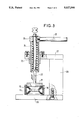
- FIG. 3 shows the method of assembly used for applying prestress
- FIG. 4 shows a response curve of a particular embodiment of a filter of the invention.
- the resonator filter of the invention comprises a member having a cylindrical cavity 10 having a dielectric resonator 11 inside it, the resonator being cylindrical in shape, for example, with its axis of symmetry ⁇ being colinear with the axis of symmetry of the said cavity 10.
- the resonator 11 is disposed in a symmetrical position inside the cavity 10.
- the cavity 10 may also be closed, if necessary, by two irises.
- the resonator 11 is held inside the cavity 10 by a system of dished washers 15 and 16. As shown in FIG. 1, the first washer 15 is mounted to bear against a rim 12 made on the inside wall of the cavity 10. The bearing surfaces of the washer 15 against the rim 12 of the cavity 10 are limited to studs 17 which are accurately machined. The resonator 11 bears against four bearing surfaces 18 made on the inside of the washer 15 and serving to hold the resonator in a symmetrical position on the axis ⁇ of the cavity 10.
- the second washer 16 is very similar in shape to the first washer 16 and has four identical bearing surfaces 18 for engaging the resonator 11. It differs in that it has a conical bearing surface 19 which engages the pointed ends of lock screws 20 passing through the cavity 10 and serving to hold the resonator 11 in place in the cavity 10 by the contact they make.
- the device of the invention may make use of cavities and adjustment devices made of silver-plated aluminum.
- the filter of the invention satisfies the folowing characteristics:
- the resonator 11 is held by a washer system (15, 16) which applies a stress designed to withstand accelerations of up to 30 g and considerable thermal stresses.
- This prestress is applied by means of the tooling shown in FIG. 3, the tooling comprising a frame 27, 28, 29 having a guide 25 fixed thereto.
- a spring 24 is imprisoned inside the guide 25 and the force set by the spring is transmitted by a finger 22 and a plate 21 to the top washer 16.
- the spring is compressed as a function of the number of turns of a lever 26.
- the tooling is calibrated to establish the relationship between number of turns and the force.
- the lock screws 20 are then put into position so they bear against the conical bearing surface 19 of the second washer 16 before raising the finger 22.
- the component parts of the filter of the invention may have the following dimensions:
- a plurality of cavities of the invention may be connected end to end in order to constitute an n-pole filter.
- an eight-pole filter which is self-correcting in the 3.7 GKz to 4.2 GKz band and which provides the performance shown by the curve in FIG. 4 where its transfer parameter is plotted as gain in decibels as a function of frequency in gigahertz.
Abstract
Description
Claims (8)
Applications Claiming Priority (2)
| Application Number | Priority Date | Filing Date | Title |
|---|---|---|---|
| FR8904906A FR2646022B1 (en) | 1989-04-13 | 1989-04-13 | DIELECTRIC RESONATOR FILTER |
| FR8904906 | 1989-04-13 |
Publications (1)
| Publication Number | Publication Date |
|---|---|
| US5027090A true US5027090A (en) | 1991-06-25 |
Family
ID=9380694
Family Applications (1)
| Application Number | Title | Priority Date | Filing Date |
|---|---|---|---|
| US07/508,445 Expired - Fee Related US5027090A (en) | 1989-04-13 | 1990-04-13 | Filter having a dielectric resonator |
Country Status (6)
| Country | Link |
|---|---|
| US (1) | US5027090A (en) |
| EP (1) | EP0392417B1 (en) |
| JP (1) | JPH02306701A (en) |
| CA (1) | CA2014514C (en) |
| DE (1) | DE69014693T2 (en) |
| FR (1) | FR2646022B1 (en) |
Cited By (18)
| Publication number | Priority date | Publication date | Assignee | Title |
|---|---|---|---|---|
| US5323129A (en) * | 1992-01-10 | 1994-06-21 | Gardiner Communications Corporation | Resonator mounting apparatus |
| GB2276039A (en) * | 1993-03-12 | 1994-09-14 | Matra Marconi Space Uk Ltd | Support arrangement for a dielectric element within a cavity, for a dieletric resonator filter |
| US5352997A (en) * | 1991-05-09 | 1994-10-04 | Nokia Telecommunication Oy | Dielectric resonator structure having resonator displaceable between support plates for adjusting resonance frequency |
| DE4316334A1 (en) * | 1993-05-15 | 1994-11-17 | Forschungsgesellschaft Fuer In | Dielectric resonator |
| US5493258A (en) * | 1993-03-12 | 1996-02-20 | Matra Marconi Space Uk Limited | Dielectric resonator demultiplexer with MIC circulators located within the support structure |
| US5517203A (en) * | 1994-05-11 | 1996-05-14 | Space Systems/Loral, Inc. | Dielectric resonator filter with coupling ring and antenna system formed therefrom |
| US5652556A (en) * | 1994-05-05 | 1997-07-29 | Hewlett-Packard Company | Whispering gallery-type dielectric resonator with increased resonant frequency spacing, improved temperature stability, and reduced microphony |
| US5698986A (en) * | 1996-02-12 | 1997-12-16 | Allen-Bradley Company, Inc. | Cigarette density monitor |
| US5880650A (en) * | 1995-05-12 | 1999-03-09 | Alcatel N.V. | Dielectric resonator for a microwave filter, and a filter including such a resonator |
| US6002311A (en) * | 1997-10-23 | 1999-12-14 | Allgon Ab | Dielectric TM mode resonator for RF filters |
| US6459346B1 (en) | 2000-08-29 | 2002-10-01 | Com Dev Limited | Side-coupled microwave filter with circumferentially-spaced irises |
| US6476686B1 (en) * | 2001-09-21 | 2002-11-05 | Space Systems/Loral, Inc. | Dielectric resonator equalizer |
| US6535087B1 (en) | 2000-08-29 | 2003-03-18 | Com Dev Limited | Microwave resonator having an external temperature compensator |
| US6538536B1 (en) * | 2000-09-27 | 2003-03-25 | Motorola, Inc. | Dielectric resonator oscillator and methods of assembly therefor |
| US6603374B1 (en) * | 1995-07-06 | 2003-08-05 | Robert Bosch Gmbh | Waveguide resonator device and filter structure provided therewith |
| WO2004082066A1 (en) * | 2003-03-11 | 2004-09-23 | Tesat Spacecom Gmbh & Co. Kg | Method and device for compensating the temperature of circular resonators |
| US20050030131A1 (en) * | 2003-08-04 | 2005-02-10 | Takehiko Yamakawa | Dielectric resonator, dielectric filter, and method of supporting dielectric resonance element |
| CN103035980A (en) * | 2011-09-30 | 2013-04-10 | 深圳市大富科技股份有限公司 | Dielectric filter and installation method, elastic piece and communication radio frequency device thereof |
Families Citing this family (1)
| Publication number | Priority date | Publication date | Assignee | Title |
|---|---|---|---|---|
| GB2288917A (en) * | 1994-04-22 | 1995-11-01 | Matra Marconi Space Uk Ltd | Dielectric resonator filter |
Citations (13)
| Publication number | Priority date | Publication date | Assignee | Title |
|---|---|---|---|---|
| DE1591362A1 (en) * | 1967-04-21 | 1970-12-23 | Philips Patentverwaltung | Coaxial line support for rigid and flexible high frequency lines |
| US3562665A (en) * | 1969-05-20 | 1971-02-09 | Rca Corp | Microwave oscillator including two bulk negative resistance devices in a three-terminal cavity |
| DE2047229A1 (en) * | 1969-12-11 | 1971-06-16 | Gen Electric And English Elect | Microwave component |
| GB1520473A (en) * | 1974-09-06 | 1978-08-09 | Murata Manufacturing Co | Dielectric resonator and microwave filter using the same |
| US4563661A (en) * | 1984-12-26 | 1986-01-07 | At&T Bell Laboratories | Dielectric for microwave applications |
| EP0173545A2 (en) * | 1984-08-21 | 1986-03-05 | The University Of Western Australia | Crystalline alumina loaded cavity resonator |
| JPS61251202A (en) * | 1985-04-27 | 1986-11-08 | Fujitsu Ltd | Dielectric filter |
| US4646038A (en) * | 1986-04-07 | 1987-02-24 | Motorola, Inc. | Ceramic resonator filter with electromagnetic shielding |
| US4661790A (en) * | 1983-12-19 | 1987-04-28 | Motorola, Inc. | Radio frequency filter having a temperature compensated ceramic resonator |
| US4667172A (en) * | 1986-04-07 | 1987-05-19 | Motorola, Inc. | Ceramic transmitter combiner with variable electrical length tuning stub and coupling loop interface |
| SU1427443A1 (en) * | 1987-04-08 | 1988-09-30 | Предприятие П/Я А-3650 | Filter |
| US4939489A (en) * | 1988-02-12 | 1990-07-03 | Alcatel Espace | Filter having a dielectric resonator |
| US4942377A (en) * | 1987-05-29 | 1990-07-17 | Murata Manufacturing Co., Ltd. | Rod type dielectric resonating device with coupling plates |
-
1989
- 1989-04-13 FR FR8904906A patent/FR2646022B1/en not_active Expired - Fee Related
-
1990
- 1990-04-09 EP EP90106746A patent/EP0392417B1/en not_active Expired - Lifetime
- 1990-04-09 DE DE69014693T patent/DE69014693T2/en not_active Expired - Fee Related
- 1990-04-11 JP JP2096163A patent/JPH02306701A/en active Pending
- 1990-04-12 CA CA002014514A patent/CA2014514C/en not_active Expired - Fee Related
- 1990-04-13 US US07/508,445 patent/US5027090A/en not_active Expired - Fee Related
Patent Citations (13)
| Publication number | Priority date | Publication date | Assignee | Title |
|---|---|---|---|---|
| DE1591362A1 (en) * | 1967-04-21 | 1970-12-23 | Philips Patentverwaltung | Coaxial line support for rigid and flexible high frequency lines |
| US3562665A (en) * | 1969-05-20 | 1971-02-09 | Rca Corp | Microwave oscillator including two bulk negative resistance devices in a three-terminal cavity |
| DE2047229A1 (en) * | 1969-12-11 | 1971-06-16 | Gen Electric And English Elect | Microwave component |
| GB1520473A (en) * | 1974-09-06 | 1978-08-09 | Murata Manufacturing Co | Dielectric resonator and microwave filter using the same |
| US4661790A (en) * | 1983-12-19 | 1987-04-28 | Motorola, Inc. | Radio frequency filter having a temperature compensated ceramic resonator |
| EP0173545A2 (en) * | 1984-08-21 | 1986-03-05 | The University Of Western Australia | Crystalline alumina loaded cavity resonator |
| US4563661A (en) * | 1984-12-26 | 1986-01-07 | At&T Bell Laboratories | Dielectric for microwave applications |
| JPS61251202A (en) * | 1985-04-27 | 1986-11-08 | Fujitsu Ltd | Dielectric filter |
| US4646038A (en) * | 1986-04-07 | 1987-02-24 | Motorola, Inc. | Ceramic resonator filter with electromagnetic shielding |
| US4667172A (en) * | 1986-04-07 | 1987-05-19 | Motorola, Inc. | Ceramic transmitter combiner with variable electrical length tuning stub and coupling loop interface |
| SU1427443A1 (en) * | 1987-04-08 | 1988-09-30 | Предприятие П/Я А-3650 | Filter |
| US4942377A (en) * | 1987-05-29 | 1990-07-17 | Murata Manufacturing Co., Ltd. | Rod type dielectric resonating device with coupling plates |
| US4939489A (en) * | 1988-02-12 | 1990-07-03 | Alcatel Espace | Filter having a dielectric resonator |
Non-Patent Citations (4)
| Title |
|---|
| 1982 IEEE MIT S International Microwave Symposium Digest, Dallas, Tex., 15 17 Jun. 1982, pp. 386 388, IEEE New York, U.S.; S. J. Fiedziuszko et al.: Miniature Filters and Equalizers Utilizing Dual Mode Dielectric Resonator Loaded Cavities . * |
| 1982 IEEE MIT-S International Microwave Symposium Digest, Dallas, Tex., 15-17 Jun. 1982, pp. 386-388, IEEE New York, U.S.; S. J. Fiedziuszko et al.: "Miniature Filters and Equalizers Utilizing Dual Mode Dielectric Resonator Loaded Cavities". |
| Patent Abstracts of Japan, vol. 11, No. 99 (E 493) 2546 , Mar. 27, 1987; & JP A 61 251202 (Fujitsu Ltd.) Nov. 8, 1986. * |
| Patent Abstracts of Japan, vol. 11, No. 99 (E-493) [2546], Mar. 27, 1987; & JP-A-251 202 (Fujitsu Ltd.) Nov. 8, 1986. |
Cited By (22)
| Publication number | Priority date | Publication date | Assignee | Title |
|---|---|---|---|---|
| US5352997A (en) * | 1991-05-09 | 1994-10-04 | Nokia Telecommunication Oy | Dielectric resonator structure having resonator displaceable between support plates for adjusting resonance frequency |
| US5323129A (en) * | 1992-01-10 | 1994-06-21 | Gardiner Communications Corporation | Resonator mounting apparatus |
| GB2276039A (en) * | 1993-03-12 | 1994-09-14 | Matra Marconi Space Uk Ltd | Support arrangement for a dielectric element within a cavity, for a dieletric resonator filter |
| US5493258A (en) * | 1993-03-12 | 1996-02-20 | Matra Marconi Space Uk Limited | Dielectric resonator demultiplexer with MIC circulators located within the support structure |
| DE4316334A1 (en) * | 1993-05-15 | 1994-11-17 | Forschungsgesellschaft Fuer In | Dielectric resonator |
| US5652556A (en) * | 1994-05-05 | 1997-07-29 | Hewlett-Packard Company | Whispering gallery-type dielectric resonator with increased resonant frequency spacing, improved temperature stability, and reduced microphony |
| US5517203A (en) * | 1994-05-11 | 1996-05-14 | Space Systems/Loral, Inc. | Dielectric resonator filter with coupling ring and antenna system formed therefrom |
| US5880650A (en) * | 1995-05-12 | 1999-03-09 | Alcatel N.V. | Dielectric resonator for a microwave filter, and a filter including such a resonator |
| US6603374B1 (en) * | 1995-07-06 | 2003-08-05 | Robert Bosch Gmbh | Waveguide resonator device and filter structure provided therewith |
| US5698986A (en) * | 1996-02-12 | 1997-12-16 | Allen-Bradley Company, Inc. | Cigarette density monitor |
| US6002311A (en) * | 1997-10-23 | 1999-12-14 | Allgon Ab | Dielectric TM mode resonator for RF filters |
| US6459346B1 (en) | 2000-08-29 | 2002-10-01 | Com Dev Limited | Side-coupled microwave filter with circumferentially-spaced irises |
| US6535087B1 (en) | 2000-08-29 | 2003-03-18 | Com Dev Limited | Microwave resonator having an external temperature compensator |
| US6538536B1 (en) * | 2000-09-27 | 2003-03-25 | Motorola, Inc. | Dielectric resonator oscillator and methods of assembly therefor |
| US6476686B1 (en) * | 2001-09-21 | 2002-11-05 | Space Systems/Loral, Inc. | Dielectric resonator equalizer |
| WO2004082066A1 (en) * | 2003-03-11 | 2004-09-23 | Tesat Spacecom Gmbh & Co. Kg | Method and device for compensating the temperature of circular resonators |
| US20060109068A1 (en) * | 2003-03-11 | 2006-05-25 | Franz-Josef Goertz | Method and device for compensating the temperature of circular resonators |
| US7375605B2 (en) | 2003-03-11 | 2008-05-20 | Tesat-Spacecom Gmbh & Co. Kg | Method and device for compensating the temperature of circular resonators |
| US20050030131A1 (en) * | 2003-08-04 | 2005-02-10 | Takehiko Yamakawa | Dielectric resonator, dielectric filter, and method of supporting dielectric resonance element |
| US7106152B2 (en) * | 2003-08-04 | 2006-09-12 | Matsushita Electric Industrial Co., Ltd. | Dielectric resonator, dielectric filter, and method of supporting dielectric resonance element |
| CN103035980A (en) * | 2011-09-30 | 2013-04-10 | 深圳市大富科技股份有限公司 | Dielectric filter and installation method, elastic piece and communication radio frequency device thereof |
| CN103035980B (en) * | 2011-09-30 | 2015-09-09 | 深圳市大富科技股份有限公司 | Dielectric filter and installation method, flexure strip and communication radio frequency device |
Also Published As
| Publication number | Publication date |
|---|---|
| DE69014693D1 (en) | 1995-01-19 |
| CA2014514C (en) | 1993-11-30 |
| EP0392417A1 (en) | 1990-10-17 |
| EP0392417B1 (en) | 1994-12-07 |
| DE69014693T2 (en) | 1995-04-27 |
| CA2014514A1 (en) | 1990-10-13 |
| JPH02306701A (en) | 1990-12-20 |
| FR2646022B1 (en) | 1991-06-07 |
| FR2646022A1 (en) | 1990-10-19 |
Similar Documents
| Publication | Publication Date | Title |
|---|---|---|
| US5027090A (en) | Filter having a dielectric resonator | |
| US4037182A (en) | Microwave tuning device | |
| US4028652A (en) | Dielectric resonator and microwave filter using the same | |
| EP2178156B1 (en) | Dielectric resonator and filter with low permittivity material | |
| US5691677A (en) | Tunable resonator for microwave oscillators and filters | |
| CA1257349A (en) | Temperature compensated microwave resonator | |
| US4692723A (en) | Narrow bandpass dielectric resonator filter with mode suppression pins | |
| EP0064799A1 (en) | Miniature dual-mode, dielectric-loaded cavity filter | |
| US5374911A (en) | Tandem cavity thermal compensation | |
| US5880650A (en) | Dielectric resonator for a microwave filter, and a filter including such a resonator | |
| US6297715B1 (en) | General response dual-mode, dielectric resonator loaded cavity filter | |
| KR102343774B1 (en) | Rf filter for improving pimd performance | |
| US4939489A (en) | Filter having a dielectric resonator | |
| US5585331A (en) | Miniaturized superconducting dielectric resonator filters and method of operation thereof | |
| US20080129422A1 (en) | Tunable or Re-Configurable Dielectric Resonator Filter | |
| KR20160118667A (en) | Resonator filter | |
| WO2000076019A1 (en) | Temperature-compensated rod resonator | |
| US7796000B2 (en) | Filter coupled by conductive plates having curved surface | |
| US6362707B1 (en) | Easily tunable dielectrically loaded resonators | |
| JPS63302601A (en) | Dielectric filter | |
| US6535087B1 (en) | Microwave resonator having an external temperature compensator | |
| JPS6322727B2 (en) | ||
| JP2572344B2 (en) | Dielectric resonator and band-pass filter using this resonator | |
| NZ248331A (en) | Cavity resonator with temperature compensator | |
| WO1993024969A1 (en) | Tuning device for microwave dielectric resonators and filters |
Legal Events
| Date | Code | Title | Description |
|---|---|---|---|
| AS | Assignment |
Owner name: ALCATEL ESPACE, 11, AVENUE DUBONNET, 92407 COURBEV Free format text: ASSIGNMENT OF ASSIGNORS INTEREST.;ASSIGNORS:THERON, BERNARD;GUEBLE, JEAN M.;LATOUCHE, YANNICK;AND OTHERS;REEL/FRAME:005668/0252 Effective date: 19900504 |
|
| FEPP | Fee payment procedure |
Free format text: PAYOR NUMBER ASSIGNED (ORIGINAL EVENT CODE: ASPN); ENTITY STATUS OF PATENT OWNER: LARGE ENTITY |
|
| FPAY | Fee payment |
Year of fee payment: 4 |
|
| FEPP | Fee payment procedure |
Free format text: PAYER NUMBER DE-ASSIGNED (ORIGINAL EVENT CODE: RMPN); ENTITY STATUS OF PATENT OWNER: LARGE ENTITY Free format text: PAYOR NUMBER ASSIGNED (ORIGINAL EVENT CODE: ASPN); ENTITY STATUS OF PATENT OWNER: LARGE ENTITY |
|
| FPAY | Fee payment |
Year of fee payment: 8 |
|
| REMI | Maintenance fee reminder mailed | ||
| LAPS | Lapse for failure to pay maintenance fees | ||
| STCH | Information on status: patent discontinuation |
Free format text: PATENT EXPIRED DUE TO NONPAYMENT OF MAINTENANCE FEES UNDER 37 CFR 1.362 |
|
| FP | Lapsed due to failure to pay maintenance fee |
Effective date: 20030625 |