US501831A - Welt attaching machine - Google Patents
Welt attaching machine Download PDFInfo
- Publication number
- US501831A US501831A US501831DA US501831A US 501831 A US501831 A US 501831A US 501831D A US501831D A US 501831DA US 501831 A US501831 A US 501831A
- Authority
- US
- United States
- Prior art keywords
- wire
- lever
- carrier
- awl
- welt
- Prior art date
- Legal status (The legal status is an assumption and is not a legal conclusion. Google has not performed a legal analysis and makes no representation as to the accuracy of the status listed.)
- Expired - Lifetime
Links
- 239000000463 material Substances 0.000 description 17
- 230000003534 oscillatory effect Effects 0.000 description 7
- 238000005452 bending Methods 0.000 description 4
- 230000001154 acute effect Effects 0.000 description 2
- 230000037431 insertion Effects 0.000 description 2
- 238000003780 insertion Methods 0.000 description 2
- 230000010355 oscillation Effects 0.000 description 2
- 230000000630 rising effect Effects 0.000 description 2
- 238000003462 Bender reaction Methods 0.000 description 1
- 229910001369 Brass Inorganic materials 0.000 description 1
- 208000024780 Urticaria Diseases 0.000 description 1
- 230000015572 biosynthetic process Effects 0.000 description 1
- 239000010951 brass Substances 0.000 description 1
- 239000000969 carrier Substances 0.000 description 1
- 229940000425 combination drug Drugs 0.000 description 1
- 150000001875 compounds Chemical class 0.000 description 1
- 238000010276 construction Methods 0.000 description 1
- 230000000694 effects Effects 0.000 description 1
- 239000002184 metal Substances 0.000 description 1
- 230000000284 resting effect Effects 0.000 description 1
- 238000009958 sewing Methods 0.000 description 1
Images


Classifications
-
- B—PERFORMING OPERATIONS; TRANSPORTING
- B25—HAND TOOLS; PORTABLE POWER-DRIVEN TOOLS; MANIPULATORS
- B25C—HAND-HELD NAILING OR STAPLING TOOLS; MANUALLY OPERATED PORTABLE STAPLING TOOLS
- B25C5/00—Manually operated portable stapling tools; Hand-held power-operated stapling tools; Staple feeding devices therefor
- B25C5/02—Manually operated portable stapling tools; Hand-held power-operated stapling tools; Staple feeding devices therefor with provision for bending the ends of the staples on to the work
- B25C5/0221—Stapling tools of the table model type, i.e. tools supported by a table or the work during operation
- B25C5/0257—Stapling tools of the table model type, i.e. tools supported by a table or the work during operation without an anvil, e.g. using staples of particular shape bent during the stapling operation without the use of external clinching means
Definitions
- I IIVVE/V TOR Hermrml'arlfirw.
- HERMANN CARL GROS a subject of the King of Wiirtemberg, residing at Ober-Ursel, near Frankforton-the Main, in Hesse-Nassau, Germany, have invented new and useful Improvements in Machines for Attaching WVelts to Boots or Shoes, of which the following is a specification.
- This machine serves for connecting the welts of boots or shoes with the insole and the upper by means of wire.
- This machine is based on the construction of'sole sewing machines in which the welt is sewed to the insoleand upper by means of waxed thread.
- metallic wire preferably brass wire.
- the wire is led to the machine from a spool or supply and is taken by a wire carrier.
- An awl or perforator on a suitable carrier puncturesfa hole into the material into which the wire is inserted and then cut to suitable length so that the wire projects at each side of the material.
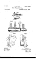
- FIG. 1 is a front elevation of the machine carried by a suitable column or support.
- Fig. 2 is a side elevation sectioned along a: 00 Fig. 1.
- Fig. 3 is a broken side elevation looking in the direction of arrow y Fig. 1.
- Fig. 4 is a plan view of the machine partly sectioned and with the cam disks removed.
- Figs. 5 and 6 are detail views showing the formation of the wire fastening.
- Figs. '7, 8 and 9 are de tail views on a larger or natural scale, Fig. 7 showing a sectional View of carriers, Fig. 8 a side elevation of a'carrier and Fig. 9 an edge view of a carrier.
- the awl carrier d (Figs. 3 and?) is journaled in well known way on the shaft a so that it can turn but not move laterally on such Serial No. 465.332. (No model.)
- the awl a is secured to the awl carrier. perforates the material to be united, namely, insole 17, upper 0 and welt a" and then by a lateral movement said awl or perforator feeds the material the length of a stitch.
- the feed motion takes place in the direction toward the left of the spectator looking at Fig. 1.
- the metal wire 01 is engaged by three adjustable guide rollers f so as to receive a bend corresponding to the circle of the curved awl and said wire is then engaged by the wire carrier.
- the wire carrier d forms the left hand journal or support for the shaft or as seen in Fig.
- the arrangement of the cutting device is as follows:
- the knife or blade m is secured to lever m fulcrumed at stud 1 on wire carrier d.
- the lever m has a roller 2 actuated by segment .9 secured to a slide 3
- the slide :9 is connected to the lever s actuated by cam E 7
- the apparatus operates as follows: By the action of segment 5 on roller 2 the lever m is actuated to press the knife m on the wire in the wire carrier, and while the roller with the wire carrier passes the distance from point t to t" (Fig. 8)
- wire carrier will not act upon the wire.
- this pressure of the knife is such as to firmly hold the wire duringthe forward stroke.
- a nose which on the further or final advance of the wire carrier exerts increased pressure on roller 2, lever m and knife m whereby the edge of the knife cuts the wire.
- the cutting is done diagonally to the direction of length of the wire so that the ends of the cut portion are pointed.
- the inner presser foot While the wire is brought into the position shown in Fig. 5 the inner and outer presser feet 10 to come against opposite sides of the material to compress the same directly in front of the wire piece at the spot where the latter is to be bent.
- the inner presser foot to is provided with a downwardly projecting point and is merely moved up and down. It is secured to the slide w (Fig. 4) having at its upper end a roller4 (Fig. 3) engaged by the forked end of lever 10 actuated by cam E
- the point of the inner presser foot to descends and enters from above into the channel of the inner sole directly after the awlhas ended its feed.
- the outer presser foot w has afourfold motion, first diagonally upward or pendulumlike in the direction of position of the welt, second, vertically upward, third, diagonally backward (pendulumlike), fourth, vertically downward against the welt. These movements are effected as follows:
- the presser foot'w is secured to a lever 20 fulcrumed' in the upper part of slide w. Below the fulcrum extends a lever w having a roller pressed by spring 6' (Fig. 2) against the disk E".
- This lever under the action of disk E effects the up and down motion of the slide to and of the lever to carrying the outer presser foot to.
- a roller on this lever w runs in a cam groove of disk E" whereby the diagonal or pendulumlike movements of the lever 'w and of the outer presser foot-w are efiect'ed.
- the outer presser foot moves on the other side vertically downward against the material and rests with a certain pressure upon the latter, that is to say upon the outer side of the welt.
- the end of the outer presser foot resting on the material or welt as seen in Fig. 5 has the form of an acute triangle the acute angle of which points toward the piece of wire.
- each cheek of this so called pliers receives a fourfold motion, first, in horizontal direction along in the direction of the joint or seam, second, forward from inside and outside against the material, third, backward away from the inner and outer edge of the material, fourth, in horizontal direction back opposite to the first direction.
- the movement of the inner plier cheek differs from that of the outer in this that the former moves at all times in constant position, while the outer cheek is under the influence of a spring and therefore yielding to accommodate difierent thicknesses of material.
- the cheek z is secured to the forward end of lever a which rests on a somewhat inclined face of the frame and is slotted at about its turning point in which slot is fitted a roller 8 (Fig. 2).
- This roller carried by screw 9 forms the fulcrum of lever 2
- the other end of the lever 2 consists of two parts, the end proper of the lever 2 and the end piece or tail 2
- Thelatter can move or play in a tube or sleeve on lever 2 and a spring 10 is interposed between the parts 2 2
- the tail piece 2 is connected by a ball joint with the lever .2 having a double fulcrurn or double jointed support .2 and having two rollers 11 and 12, one of which runs in a cam groove in disk E while the other runs on the disk E and is forced against said disk by spring 13.
- the disk E and'itscam groove are so formed as to impart to lever a a lateral as also vertical oscillation, which movements being imparted to lever z cause the latter to move backward and forward as guided by its slot and also to swing or turn about the screw 9.
- the inner plier cheek z is secured to lever z havinga double fulcrum or double jointed support .2 and having. two rollers 14 and 15 actuated by disk E in a similar manner as the disk E 'actuates rollers 11 and 12 of lever 2
- the lever 2 receives the same kind of motion as justdescribed namely laterally back and forth as also back and forth in a vertical direction.
- the plier cheeks 22' move horizontally in a direction toward the wire fastening last formed whereby the wire piece is bent about the inner and outer presser feet w and w close to the inner and outer edges of the material.
- the outer plier check 2' consists of two parts, being provided with the finger 2 (Figs. 4, 5 and 6) movable in the longitudinal direction of lever 2 and moved by spring 16 forward or toward the outer presser foot w. On the advance of the cheek z the finger z" againstthe suitably formed presser foot to,
- the lever .ztthen moves forward or toward the work whereby the outer end of the hook or'clamp is pressed toward or rather into the material and against the inner check 2 and the inner presser foot to so that also the inner bent end of the wire piece is pressed into the inner edge of the channel of the insole.
- the outer cheek z is so connected to lever'z as to be adjustable but besides in consequence of spring 10 between the parts 2 2 the pressure of lever 2 on cheek z is not'positive so that the cheek 2 can yield automatically to inequalities in the thickness of the material.
- the cheeks z 2 make a return stroke or move away from the material and move horizontally at proper moments, the point of the inner presser foot w is moved out of the channel in the insole and the operation for forming a new stitch is repeated.
- the combi nation with an awl or perforator of an oscillatory wire-carrier for inserting the wire into the perforation made by the awl or perforator, a cutter pivotally mounted on and oscillating with the wire-carrier, means for operating the awl or perforator, oscillating the wire-carrier, and vibrating the cuttcr on said wire-carrier, and pliers for bending the end portions of the severed part of the wire, and pressing them against the inner and outer sides of the The wire is thus bent into a clampas seen in Fig. 6..
- the point of t-hepresser foot w by reason of materialbeing fastened, substantially as described, i.
- the combination with mechanism for inserting Wire pieces into the portion to be united, of a rising and falling presser foot to, a rising and falling, and backward and forward moving presser foot w
Landscapes
- Engineering & Computer Science (AREA)
- Mechanical Engineering (AREA)
- Footwear And Its Accessory, Manufacturing Method And Apparatuses (AREA)
Description
(No Model.)
.LD 6 e h s w e h s 4 a N I H m S 0 .%m m HM T L w.
No. 501,831. Patented July 18, 1893.
lA/I/E/V 70/? Hermann (krl draw.
)1 TTOR/VEYS.
WITNESSES 2 t e e h s u e e h s 4 R N I H m S 0w R Gm H G M T H M T L E W (No Model.)
N0: 501,831. Patented July 18,1893.
I IIVVE/V TOR. Hermrml'arlfirw.
BY ATTORNEYS WITNESSES.
C MZ (No Model.) 4 Sheets- Sheet 4.
H. G. GROS. WELT ATTAG'HING MACHINE. No. 501,831 Patented July 18,-1893.
I I I I A UNrTnn STATES PATENT OFFICE.
HERMANN CARL GROS, OFOBER-URSEL, GERMANY.
WELT-ATTACHING MACHINE.
sPEoIFIoATIoN forming part of Letters Patent No. 501,831, dated July 18,1893
Application filed March 9, 1893.
To all whom it may concern.-
Be it known that. I, HERMANN CARL GROS, a subject of the King of Wiirtemberg, residing at Ober-Ursel, near Frankforton-the Main, in Hesse-Nassau, Germany, have invented new and useful Improvements in Machines for Attaching WVelts to Boots or Shoes, of which the following is a specification.
This machine serves for connecting the welts of boots or shoes with the insole and the upper by means of wire.
This machine is based on the construction of'sole sewing machines in which the welt is sewed to the insoleand upper by means of waxed thread. In this case however in place of waxed thread there is employed metallic wire, preferably brass wire. The wire is led to the machine from a spool or supply and is taken by a wire carrier. An awl or perforator on a suitable carrier puncturesfa hole into the material into which the wire is inserted and then cut to suitable length so that the wire projects at each side of the material. The
projecting ends are then bent and pressed firmly against the material so that by repeating the action of the machine a row of fastenings or clamps is formed taking the place of the former seam of waxed thread.
The machine is illustrated in the annexed drawings in which- Figure 1, is a front elevation of the machine carried by a suitable column or support. Fig. 2, is a side elevation sectioned along a: 00 Fig. 1. Fig. 3, is a broken side elevation looking in the direction of arrow y Fig. 1. Fig. 4, is a plan view of the machine partly sectioned and with the cam disks removed. Figs. 5 and 6, are detail views showing the formation of the wire fastening. Figs. '7, 8 and 9, are de tail views on a larger or natural scale, Fig. 7 showing a sectional View of carriers, Fig. 8 a side elevation of a'carrier and Fig. 9 an edge view of a carrier.
Upon the support or frame K are supported a pair of columns S S in which is .journaled the shaftW upon which are fastened the cams or eccentric disks E E 1 1 E which latter impart motion to various levers and parts.
The awl carrier d (Figs. 3 and?) is journaled in well known way on the shaft a so that it can turn but not move laterally on such Serial No. 465.332. (No model.)
same time this carrier must partake of the.
horizontal oscillation or sliding reciprocation imparted in well known way to shaft a by lever 25. The awl a is secured to the awl carrier. perforates the material to be united, namely, insole 17, upper 0 and welt a" and then by a lateral movement said awl or perforator feeds the material the length of a stitch. In the drawings the feed motion takes place in the direction toward the left of the spectator looking at Fig. 1. The metal wire 01 is engaged by three adjustable guide rollers f so as to receive a bend corresponding to the circle of the curved awl and said wire is then engaged by the wire carrier. The wire carrier d forms the left hand journal or support for the shaft or as seen in Fig. 7 and said carrier is so journaled in the frame or supportK that it can swing but can not move laterally. Its swing is received from toothed segment lever s and cam E A cutting apparatus described hereinafterisconnectedtothe wire carrier so as to partake of its backward and forward movements. If the wire carrier is back or in its rear portion away from thework thev In its forward stroke (Fig. 3) the awl I from the work the wire carrier moves forward loo back the wire, the latter remaining in the position it occupied at the moment of cutting.
The arrangement of the cutting device is as follows: The knife or blade m is secured to lever m fulcrumed at stud 1 on wire carrier d. The lever m has a roller 2 actuated by segment .9 secured to a slide 3 The slide :9 is connected to the lever s actuated by cam E 7 As seen in Figs. 2, 8 and 9 the apparatus operates as follows: By the action of segment 5 on roller 2 the lever m is actuated to press the knife m on the wire in the wire carrier, and while the roller with the wire carrier passes the distance from point t to t" (Fig. 8)
wire carrier will not act upon the wire.
on the inner side of segment 5 this pressure of the knife is such as to firmly hold the wire duringthe forward stroke. At the point 2" directly in advance of the end of the stroke of the wire carrier is a nose which on the further or final advance of the wire carrier exerts increased pressure on roller 2, lever m and knife m whereby the edge of the knife cuts the wire. The cutting is done diagonally to the direction of length of the wire so that the ends of the cut portion are pointed. When the wire is cut the segment .9 on slide .9 is raised by lever s and cam E and the lever m and knife m are pressed back by spring 3 so that the knife on the back stroke of the After the return stroke the segment 3 again presses lightly on roller 2 whereby the knifemagain takes hold of the wire and the operation is repeated. While the wire is brought into the position shown in Fig. 5 the inner and outer presser feet 10 to come against opposite sides of the material to compress the same directly in front of the wire piece at the spot where the latter is to be bent. The inner presser foot to is provided with a downwardly projecting point and is merely moved up and down. It is secured to the slide w (Fig. 4) having at its upper end a roller4 (Fig. 3) engaged by the forked end of lever 10 actuated by cam E The point of the inner presser foot to descends and enters from above into the channel of the inner sole directly after the awlhas ended its feed. The outer presser foot w has afourfold motion, first diagonally upward or pendulumlike in the direction of position of the welt, second, vertically upward, third, diagonally backward (pendulumlike), fourth, vertically downward against the welt. These movements are effected as follows: The presser foot'w is secured to a lever 20 fulcrumed' in the upper part of slide w. Below the fulcrum extends a lever w having a roller pressed by spring 6' (Fig. 2) against the disk E". This lever under the action of disk E effects the up and down motion of the slide to and of the lever to carrying the outer presser foot to. A roller on this lever w runs in a cam groove of disk E" whereby the diagonal or pendulumlike movements of the lever 'w and of the outer presser foot-w are efiect'ed. As soon as the inner presser foot w is in the above last mentioned position, the outer presser foot moves on the other side vertically downward against the material and rests with a certain pressure upon the latter, that is to say upon the outer side of the welt. The end of the outer presser foot resting on the material or welt as seen in Fig. 5 has the form of an acute triangle the acute angle of which points toward the piece of wire. When in this position (Fig. 5) two other instruments come into operation, namely, the benders and pressers z 2 which taken together from a sort of pliers. Each cheek of this so called pliers receives a fourfold motion, first, in horizontal direction along in the direction of the joint or seam, second, forward from inside and outside against the material, third, backward away from the inner and outer edge of the material, fourth, in horizontal direction back opposite to the first direction. The movement of the inner plier cheek differs from that of the outer in this that the former moves at all times in constant position, while the outer cheek is under the influence of a spring and therefore yielding to accommodate difierent thicknesses of material. The cheek z is secured to the forward end of lever a which rests on a somewhat inclined face of the frame and is slotted at about its turning point in which slot is fitted a roller 8 (Fig. 2). This roller carried by screw 9 forms the fulcrum of lever 2 The other end of the lever 2 consists of two parts, the end proper of the lever 2 and the end piece or tail 2 Thelatter can move or play in a tube or sleeve on lever 2 and a spring 10 is interposed between the parts 2 2 The tail piece 2 is connected by a ball joint with the lever .2 having a double fulcrurn or double jointed support .2 and having two rollers 11 and 12, one of which runs in a cam groove in disk E while the other runs on the disk E and is forced against said disk by spring 13. The disk E and'itscam groove are so formed as to impart to lever a a lateral as also vertical oscillation, which movements being imparted to lever z cause the latter to move backward and forward as guided by its slot and also to swing or turn about the screw 9. The inner plier cheek z is secured to lever z havinga double fulcrum or double jointed support .2 and having. two rollers 14 and 15 actuated by disk E in a similar manner as the disk E 'actuates rollers 11 and 12 of lever 2 The lever 2 receives the same kind of motion as justdescribed namely laterally back and forth as also back and forth in a vertical direction.
Referring to the position of parts shown'in Figi 5 the plier cheeks 22' move horizontally in a direction toward the wire fastening last formed whereby the wire piece is bent about the inner and outer presser feet w and w close to the inner and outer edges of the material. The outer plier check 2' consists of two parts, being provided with the finger 2 (Figs. 4, 5 and 6) movable in the longitudinal direction of lever 2 and moved by spring 16 forward or toward the outer presser foot w. On the advance of the cheek z the finger z" againstthe suitably formed presser foot to,
and when past the edge of the presser foot w the finger will advance under the pressure of spring 16 to bend over the outer point. of the wire piece which thereafter entersthe material to form, a hook or holder.
the pendulum like oroscillating motion of lever wt now moves diagonally upward away from under cheek z' student of the wire loop or hook formed about the presser foot to,
The lever .ztthen moves forward or toward the work whereby the outer end of the hook or'clamp is pressed toward or rather into the material and against the inner check 2 and the inner presser foot to so that also the inner bent end of the wire piece is pressed into the inner edge of the channel of the insole. The outer cheek z is so connected to lever'z as to be adjustable but besides in consequence of spring 10 between the parts 2 2 the pressure of lever 2 on cheek z is not'positive so that the cheek 2 can yield automatically to inequalities in the thickness of the material.
After the Wire ends have been pressed in, the cheeks z 2 make a return stroke or move away from the material and move horizontally at proper moments, the point of the inner presser foot w is moved out of the channel in the insole and the operation for forming a new stitch is repeated.
What I claim as new, and desire to secure by Letters Patent, is-
1. In a welt-attaching machine, the combination with an oscillatory awl or perforator, of an oscillatory Wire-carrier for inserting the wire into the perforation made by the'awl, a cutter for severing the wire, and inner and outer pliers for bending the opposite end portions of the severed parts of the wire, and pressing them against the inner and outer sides of the material being fastened, substan tially-as described.
2. In a welt-attaching machine, the combination-with an awl or perforator, of an oscil-l latory wire-carrier for inserting the wire into the perforation made by the awl or perforator, a cutter pivotally mounted on and oscillating with the wire-carrier, and means for operating the awl or perforator, oscillating the wirecarrier, and vibrating the cutter on said wirecarrier, substantially as described.
3. In a welt-attaching machine, the combi nation with an awl or perforator, of an oscillatory wire-carrier for inserting the wire into the perforation made by the awl or perforator, a cutter pivotally mounted on and oscillating with the wire-carrier, means for operating the awl or perforator, oscillating the wire-carrier, and vibrating the cuttcr on said wire-carrier, and pliers for bending the end portions of the severed part of the wire, and pressing them against the inner and outer sides of the The wire is thus bent into a clampas seen in Fig. 6.. The point of t-hepresser foot w by reason of materialbeing fastened, substantially as described, i.
4.111 ajwelt-attaching machine, the combination of an oscillatory'awl of perforator, an oscillatory wire-carrier for inserting the wire into the perforation made by. the awl or ,perforator, a lengthwise movable shaft on which the awl or perforator and the wire-carrier are mounted side by side, and means for oscillating the awl or perforator and the wire-carrier, and moving the said shaft lengthwise, substantially as described, H H 1 j I 5. In a welt-attaching machine, the combi-, nation with an awl or perforator, of an oscillatory wire-carrier, guiding and curving devices mounted uponsaid oscillatory wire-carrier for imparting to thewire the proper bend for the insertion thereotiaud means for operating the awl or perforator, and oscillating the wire-carrier, substantially as described.
6. The combination with an awl or perforator of a wire carrier 01' and guiding and curving rollers f substantially as described, for imparting to the wire the proper bend for the insertion thereof.
7. The'combination with an awl or perforator, of an oscillating wire-carrier (13pm vided with a rocking cutter for severing the wire into proper lengths, and means for oper ating the awl or perforator, oscillating the wire-carrier, and rocking the cutter on the wire carrier, substantially; as described.
8. The combination with an awl or perforator and a wire carrier 01' provided with a knife on and knife lever m, of a segment 8 for actuating the lever, a slide .9 for the segment and an actuating lever .9 for the slide, substantially as described. a
9. In a welt attaching machine the combination with mechanism substantially as described for inserting wire pieces into the parts to be united of the plier cheeks 2.2 actuating mechanism substantially as described for the cheek z and an actuating lever for' the cheek z said'lever being composed of two spring interposed parts or sections 2 ,2 an actuating lever e for the first named lever and a ball joint for connecting said'two levers, substantially as described.
10. In a welt attaching machine the combination with mechanism substantially as described for inserting wirepieces into the parts to be'united of the plier cheeks zz for bending the wire and actuating mechanism substantially as described for said plier cheeks, said check a being provided with a yielding spring-pressed finger 21, substantially as described. d
11. In a welt-attaching machine, the combination with mechanism, substantially as described, for inserting Wire pieces into the portion to be united, of a rising and falling presser foot to, a rising and falling, and backward and forward moving presser foot w, plier checks 2 z opposing the presser foot for bending the end portions of the wire pieces and pressing them against the parts to be united, and means for operating the presser feet and plier cheeks, substantially as described.
12. In a Welt attaching machine the combination with mechanism substantially as described for inserting wire pieces, of presser feet to w, actuating mechanism substantially as described for the presser foot w and an actuating lever to for the presser foot 10' said lever having a movable fulcrumand a lever 20 for actuating the fulcrum, substantially as described.
13. In a Welt attaching machine the combination with mechanism substantially as described for inserting wire pieces, of presser feet 20 w, a slide w and lever 10 for actuating one of the presser feet and a movably fulcrumed lever for actuating the other presser foot, substantially as described.
14. In a welt attaching machine the combination with mechanism substantially as described for inserting wire pieces, of plier cheeks z z and actuating levers for said cheeks, each of said levers having a double jointed fulcrum so as to be capable of compound motion, substantially as described.
In testimony whereof I have hereunto set my hand in the presence of two subscribing witnesses.
I-IERMANN CARL eRo's.
Witnesses:
DEAN B. MASON, ALVESTO S. HOGUE.
Publications (1)
| Publication Number | Publication Date |
|---|---|
| US501831A true US501831A (en) | 1893-07-18 |
Family
ID=2570668
Family Applications (1)
| Application Number | Title | Priority Date | Filing Date |
|---|---|---|---|
| US501831D Expired - Lifetime US501831A (en) | Welt attaching machine |
Country Status (1)
| Country | Link |
|---|---|
| US (1) | US501831A (en) |
-
0
- US US501831D patent/US501831A/en not_active Expired - Lifetime
Similar Documents
| Publication | Publication Date | Title |
|---|---|---|
| US507472A (en) | bateman | |
| US354052A (en) | Eppler | |
| US855244A (en) | Machine for uniting welts to stock. | |
| US938474A (en) | Automatic clench-nailer. | |
| US215547A (en) | Improvement in machines for pricking and trimming soles | |
| US669023A (en) | Machine for making and inserting metallic fastenings. | |
| US282602A (en) | Nailing-machine | |
| US122985A (en) | Improvement in boot and shoe nailing-machines | |
| US1228768A (en) | Fastener-setting machine. | |
| US438100A (en) | Peters co | |
| US444126A (en) | The soles and uppees of boots ob | |
| US723468A (en) | Sole rough-rounding and channeling machine. | |
| US440394A (en) | Boot or shoe nailing machine | |
| US381988A (en) | Sewing-machine for uniting soles to uppers | |
| US641719A (en) | Sewing-machine. | |
| US123592A (en) | strong | |
| US647599A (en) | Trimming attachment for pegging-machines. | |
| US735499A (en) | Shoe-pegging machine. | |
| US1284856A (en) | Sewing-machine. | |
| US558261A (en) | cowburn | |
| US539481A (en) | Sewing-machine for lasting boots or shoes | |
| US935492A (en) | Slugging-machine for boots and shoes. | |
| US950693A (en) | Machine for driving fastenings into work. | |
| US347323A (en) | Staple forming and driving machine | |
| US571796A (en) | Marietta reece and francis |