US501035A - Package-carrier apparatus - Google Patents
Package-carrier apparatus Download PDFInfo
- Publication number
- US501035A US501035A US501035DA US501035A US 501035 A US501035 A US 501035A US 501035D A US501035D A US 501035DA US 501035 A US501035 A US 501035A
- Authority
- US
- United States
- Prior art keywords
- block
- latch
- carrier
- dog
- basket
- Prior art date
- Legal status (The legal status is an assumption and is not a legal conclusion. Google has not performed a legal analysis and makes no representation as to the accuracy of the status listed.)
- Expired - Lifetime
Links
- 230000000694 effects Effects 0.000 description 3
- 238000010276 construction Methods 0.000 description 2
- 210000005069 ears Anatomy 0.000 description 2
- 230000001174 ascending effect Effects 0.000 description 1
- 238000005452 bending Methods 0.000 description 1
- 239000000969 carrier Substances 0.000 description 1
- 230000007547 defect Effects 0.000 description 1
- 230000001788 irregular Effects 0.000 description 1
Images

Classifications
-
- B—PERFORMING OPERATIONS; TRANSPORTING
- B66—HOISTING; LIFTING; HAULING
- B66C—CRANES; LOAD-ENGAGING ELEMENTS OR DEVICES FOR CRANES, CAPSTANS, WINCHES, OR TACKLES
- B66C11/00—Trolleys or crabs, e.g. operating above runways
- B66C11/02—Trolleys or crabs, e.g. operating above runways with operating gear or operator's cabin suspended, or laterally offset, from runway or track
- B66C11/04—Underhung trolleys
- B66C11/06—Underhung trolleys running on monorails
Definitions
- My invention relates to that type of carriers wherein a basket, having its handle-rods meeting in or secured to a latch-block, is automatically attached to or detached from a carriage or traveler running upon ways by means of lifting-arms or hooks located at each end of the ways and raised or lowered by suitable mechanism controlledbyhand.
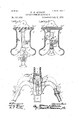
- Figure 1 is a side elevation of apparatus embodying my improvement.
- Fig. 2 is a vertical section therethrough parallel with the length of the line, the carrier being omitted and the parts about to be attached together;
- Fig. 3 a similar section with the parts connected, showing, in dotted lines, a further position when the parts are to be detached; and
- Fig. 4 is an irregular section through said parts, transversely to the preceding figures.
- A is a carriage or traveler, having, mounted in standards, A, at each end grooved wheels, B, B, which embrace and run upon Serial No. 466,158. (No model.)
- brackets Pivoted centrally to the base-bar of this traveler by means of ears, 0, is a bracket or carrier-block, 0, having bifurcated depending arms, 0, cu rved outwardly at the lower ends. From the tops of these arms lugs, 0, project upwardly from shoulders on each side of the pivotal ears to enter between and confine the coiled lower ends of springs, 0 the upper ends of which are seated in sockets, 0 in the base-bar of the traveler, thus cushioning the bracket, or the carrier-block against the swaying of the basket which it conveys.
- the forked arms of this carrier-block are both recessed from the inner faces outwardly and in the recess of one of these arms, just above the point of convergence, is a trip-bar and rest, D, while in the opposite arm, at a point slightly more elevated, is a second bar or rest, D, which may be termed the heel-rest, and at a still higher elevation on'the same side of the slot between the arms but at the inner edge of the arm on said side, is a third bar or stop,.
- E is a latch-block having outwardly and downwardly curved arms, E, giving it a yoke shape, and to the extreme ends of which the handle-bars of the basket are intended to be fastened by sockets, e, and screws, 6-, which latter prevent the withdrawal of the bars when inserted into the sockets.
- the central web, E of this latch-block is of such thickness or diameter as to pass readily, but not too loosely, into the vertical slot between the arms of the carrier-block or bracket, while on each side of said web it has outsetting flanges or shoulders, 6 to embrace the exterior faces of these arms, such shoulders merging at their top into outwardly curving or flaring plates, e which serve to guide and direct the latch-block into engagement with the arms of thecarrier-block.
- F is a dog or tumbler pivoted centrally of the web of the latch-block and having one end drawn out into a point or too, f, and the other end broader and heavier and somewhat forked or fish-tailed to afford a heel, f, and a shoulder, f and overbalance the too.
- a spring, G projects upward from the base of the web into the slot, g, in which this dog plays so as to come in contact with and support its weighted end or heel when the latter is in its normal position, and prevent it passing beyond a given point unless forceisused.
- these pressers are made as curved plate-springs, H, attached by their lower ends to the sunken faces of the carrierblock on each side of the slot therein, and lying nearly flat thereagainst for some distance along said slot and then bending up and over outwardly from a point just short of where the flanges of the latch-block depart in the outward curvature when said'block is engaged, and in the position indicated in the third and fourth figures of the drawings.
- the latchblock In order to effect the engagement, the latchblock, it will be understood, is raised to the position shown in dotted lines in said fourth figure, com pressing the springs and flattening them down against the sides of the block, and then is lowered to the position shown in full lines, wherein the springs are expanded and exert downward force upon the latchblock sufficient to resist anything but a forcible upward push, thus preventing the dog from reaching such a position, unless intentionally, as to permit disengagement. To detach the basket it is simply pushed up against the springs until the dog is disengaged, and is then lowered from the bracket.
Landscapes
- Engineering & Computer Science (AREA)
- Mechanical Engineering (AREA)
- Buckles (AREA)
Description
2 sheets -sheet 1.
(No Model.)
W. H. AJLB'AOH. PACKAGE CARRIER APPARATUS.
No. 501,035. Patented July 4, 1893.
NITED STATES PATENT OFFICE.
WILLIAM H. ALBAGl-I, OF MANSFIELD, OHIO.
PACKAGE-CARRIER APPARATUS.
SPECIFICATION forming part of Letters Patent No. 501,035, dated July 4, 1893.
Application filed March 15, 1893.
To all whom/it may concern.-
Be it known that I, WILLIAM H. ALBAOH, a citizen of the United States, residing at Mansfield, in the county of Richland and State of Ohio, have invented certain new and useful Improvements in Package-Carrier Apparatus, of which the following is a specification.
My invention relates to that type of carriers wherein a basket, having its handle-rods meeting in or secured to a latch-block, is automatically attached to or detached from a carriage or traveler running upon ways by means of lifting-arms or hooks located at each end of the ways and raised or lowered by suitable mechanism controlledbyhand. Heretofore, owing to the fact that the preliminary detaching movement like the attaching movement is a lifting one, such baskets have been peculiarly liable to become detached in their passage between stations, either by striking obstructions which tended to raise them, or by being accidentally struck and lifted, or else by the spring action or resiliency of the ways upon which the traveler runs swaying them up and throwing the latch-block high enough to disengage the latch and permit it to assume its normal or inoperative position. In the present invention I propose to remedy this defect by interposing springs between the carrier-block or bracket and latchblock which will yield to a positive upward movement of the basket sufficiently to allow the two to become engaged, or to be disengaged, but will so far counteract any tendency to jump or jolt, or the effects of any unintentional upward push, as to insure the stability of the attachment.
In the drawings: Figure 1 is a side elevation of apparatus embodying my improvement. Fig. 2 is a vertical section therethrough parallel with the length of the line, the carrier being omitted and the parts about to be attached together; Fig. 3 a similar section with the parts connected, showing, in dotted lines, a further position when the parts are to be detached; and Fig. 4 is an irregular section through said parts, transversely to the preceding figures.
A is a carriage or traveler, having, mounted in standards, A, at each end grooved wheels, B, B, which embrace and run upon Serial No. 466,158. (No model.)
wires forming the track-way. Pivoted centrally to the base-bar of this traveler by means of ears, 0, is a bracket or carrier-block, 0, having bifurcated depending arms, 0, cu rved outwardly at the lower ends. From the tops of these arms lugs, 0, project upwardly from shoulders on each side of the pivotal ears to enter between and confine the coiled lower ends of springs, 0 the upper ends of which are seated in sockets, 0 in the base-bar of the traveler, thus cushioning the bracket, or the carrier-block against the swaying of the basket which it conveys. The forked arms of this carrier-block are both recessed from the inner faces outwardly and in the recess of one of these arms, just above the point of convergence, is a trip-bar and rest, D, while in the opposite arm, at a point slightly more elevated, is a second bar or rest, D, which may be termed the heel-rest, and at a still higher elevation on'the same side of the slot between the arms but at the inner edge of the arm on said side, is a third bar or stop,.
D which may be termed the engaging stop.
E is a latch-block having outwardly and downwardly curved arms, E, giving it a yoke shape, and to the extreme ends of which the handle-bars of the basket are intended to be fastened by sockets, e, and screws, 6-, which latter prevent the withdrawal of the bars when inserted into the sockets. The central web, E of this latch-block is of such thickness or diameter as to pass readily, but not too loosely, into the vertical slot between the arms of the carrier-block or bracket, while on each side of said web it has outsetting flanges or shoulders, 6 to embrace the exterior faces of these arms, such shoulders merging at their top into outwardly curving or flaring plates, e which serve to guide and direct the latch-block into engagement with the arms of thecarrier-block.
F is a dog or tumbler pivoted centrally of the web of the latch-block and having one end drawn out into a point or too, f, and the other end broader and heavier and somewhat forked or fish-tailed to afford a heel, f, and a shoulder, f and overbalance the too. A spring, G, projects upward from the base of the web into the slot, g, in which this dog plays so as to come in contact with and support its weighted end or heel when the latter is in its normal position, and prevent it passing beyond a given point unless forceisused.
In uniting the latch-block to the carrierblock, the parts being in the position shown in full lines in Fig. 2 wherein the dog is at the normal, the basket is lifted until the laterally projecting toe of the dog comesincontact with the inclined under surface of the trip-bar, which stops it while the latch-block continues its ascent, swinging the dog around into the position shown in dotted lines, and the ascending movement still continuing, the upper edge of the heel comes in contact with the engaging stop just as the toe of the dog has cleared the trip-bar. Now if it were not for the shoulder, f the dog would swing back to the normal and the parts would be disengaged by simply pulling down the basket and latch-block or allowing them to descend, but this shoulder riding against the vertical face of the stop, and retaining its contact therewith until the latch-block is sufficiently lowered to prevent all possibility of the heel of the dog passing the intermediate rest-bar, causes the toe and heel respectively to be come engaged with their respective rest-bars, as in full lines in Fig. 3 of the drawings, when the fastening is complete. To disengage the basket it is again lifted when the heel of the dog, being the heaviest, continues in contact with the upper bar, and the toe, being the lighter, swings up into the position represented in dotted lines until the heel slips off of its rest. Then there is no impediment to the disengagement of parts, except the contact of the upper edge of the trip-bar with the toe of the dog, as thelatter is drawn down, which, however, is provided for by the yielding of the spring in contact with the heel and the basket therefore is free to descend by its own weight.
It is evident from the construction thus far described that anything that tends to jolt the latch-block or basket so as to raise the two relatively to the carrier-block is apt to disengage the basket and let it fall by permitting the dog or tumbler to rise high enough to swing around into the disengaging position when the force of the spring upon its heel will not be sufficient to overcome and resist the weight of the basket. To prevent the effects of this jolting I apply spring-pressers to the carrier-block, in contact with which the shoulders of the latch-block come and which yield to the upward pressure of the shoulders in the engaging operation and press down upon the block to resist any tendency to jolt or jump, after the engagement has been effected. In the preferred form of the invention these pressers are made as curved plate-springs, H, attached by their lower ends to the sunken faces of the carrierblock on each side of the slot therein, and lying nearly flat thereagainst for some distance along said slot and then bending up and over outwardly from a point just short of where the flanges of the latch-block depart in the outward curvature when said'block is engaged, and in the position indicated in the third and fourth figures of the drawings.
In order to effect the engagement, the latchblock, it will be understood, is raised to the position shown in dotted lines in said fourth figure, com pressing the springs and flattening them down against the sides of the block, and then is lowered to the position shown in full lines, wherein the springs are expanded and exert downward force upon the latchblock sufficient to resist anything but a forcible upward push, thus preventing the dog from reaching such a position, unless intentionally, as to permit disengagement. To detach the basket it is simply pushed up against the springs until the dog is disengaged, and is then lowered from the bracket.
I do not propose to limit myself to the application of springs in the precise form and number shown, as it is evident that many ways may be adopted to interpose a spring or springs between the latch-block and the carrier-bracket in such manner as to yield sufficiently for the engagement and then ex pand between the two so as to prevent disengagement; neither do I consider it essential that the springs should be borne by the carrier-block, although this is obviously their more convenient location; nor do I propose to limit myself herein to the described construction of the engaging and disengaging devices so far as concerns their relation to the springs, as there are several forms of latches known in the art whereby engagement and disengagement is eifected by the same lifting movement as herein, and with which the tendency to disengagement by jolting is the same and capable of being overcome by the same application of resisting forces; but
What I do claim is l. The combination substantially as hereinbefore set forth, of the carrier-block, the latch-block, and their engaging and disenga ing devices, and a spring-presser arranged between the latch-block and carrier-block to hold the two against disengagement.
2. The combination substantially as hereinbefore set forth, of the carrier-block, the latch-block, the latch-dog, and a spring or springs arranged upon the carrier-block to yield before the latch-block to permit its engagement with the carrier-block and to expand to hold it in such engagement.
3. The combination substantially as hereinbefore set forth, of the carrier-block, the latch-block and their engaging and disengaging devices, and the curved plate-springs arranged at the sides of the slot in the carrierblock to act upon the flanges of the latchblock.
WILLIAM H. ALBACI-I.
Witnesses:
M. E. SHIELDS, A. S. WELLS.
Publications (1)
| Publication Number | Publication Date |
|---|---|
| US501035A true US501035A (en) | 1893-07-04 |
Family
ID=2569870
Family Applications (1)
| Application Number | Title | Priority Date | Filing Date |
|---|---|---|---|
| US501035D Expired - Lifetime US501035A (en) | Package-carrier apparatus |
Country Status (1)
| Country | Link |
|---|---|
| US (1) | US501035A (en) |
-
0
- US US501035D patent/US501035A/en not_active Expired - Lifetime
Similar Documents
| Publication | Publication Date | Title |
|---|---|---|
| US302907A (en) | Reversible hay-carrier | |
| US226330A (en) | Passenger-elevator | |
| US451481A (en) | Draw-head and coupling mechanism for railway-cars | |
| US955628A (en) | Safety locking mechanism for package-carriers. | |
| US147350A (en) | Improvement in car-couplings | |
| US297459A (en) | Safety-clutch for elevators | |
| US784448A (en) | Trolley. | |
| US1128987A (en) | Car-coupling. | |
| US408456A (en) | Hoisting and conveying machine | |
| CN110282365B (en) | A yarn-dropping prevention device for coarse-fine combined conveying system | |
| US1189387A (en) | Anticreep device. | |
| US85979A (en) | Improved car-coupling | |
| US228473A (en) | Elevator | |
| US586314A (en) | Railroad-lamp elevator | |
| US655229A (en) | Car-coupling. | |
| US670704A (en) | Casing-elevator. | |
| US867753A (en) | Car-coupling. | |
| US496280A (en) | Territory | |
| US367944A (en) | Geoege w | |
| US485512A (en) | Place | |
| US525658A (en) | kerlin | |
| US1480966A (en) | Wheel dog | |
| US1207550A (en) | Railroad-bridge warning. | |
| US295985A (en) | Car-coupling | |
| US557942A (en) | barry |