US5007184A - Safety shoe - Google Patents
Safety shoe Download PDFInfo
- Publication number
- US5007184A US5007184A US07/369,121 US36912189A US5007184A US 5007184 A US5007184 A US 5007184A US 36912189 A US36912189 A US 36912189A US 5007184 A US5007184 A US 5007184A
- Authority
- US
- United States
- Prior art keywords
- flange
- toe box
- steel toe
- thickness
- safety shoe
- Prior art date
- Legal status (The legal status is an assumption and is not a legal conclusion. Google has not performed a legal analysis and makes no representation as to the accuracy of the status listed.)
- Expired - Fee Related
Links
- 229910000831 Steel Inorganic materials 0.000 claims abstract description 31
- 239000010959 steel Substances 0.000 claims abstract description 31
- 239000004698 Polyethylene Substances 0.000 claims abstract description 5
- -1 polyethylene Polymers 0.000 claims abstract description 5
- 229920000573 polyethylene Polymers 0.000 claims abstract description 5
- 239000000463 material Substances 0.000 claims abstract description 4
- 230000014759 maintenance of location Effects 0.000 claims 1
- 230000015572 biosynthetic process Effects 0.000 description 4
- 230000004048 modification Effects 0.000 description 2
- 238000012986 modification Methods 0.000 description 2
- 238000005299 abrasion Methods 0.000 description 1
- 238000010276 construction Methods 0.000 description 1
- 230000000694 effects Effects 0.000 description 1
Images

Classifications
-
- A—HUMAN NECESSITIES
- A43—FOOTWEAR
- A43B—CHARACTERISTIC FEATURES OF FOOTWEAR; PARTS OF FOOTWEAR
- A43B7/00—Footwear with health or hygienic arrangements
- A43B7/32—Footwear with health or hygienic arrangements with shock-absorbing means
-
- A—HUMAN NECESSITIES
- A43—FOOTWEAR
- A43B—CHARACTERISTIC FEATURES OF FOOTWEAR; PARTS OF FOOTWEAR
- A43B23/00—Uppers; Boot legs; Stiffeners; Other single parts of footwear
- A43B23/08—Heel stiffeners; Toe stiffeners
- A43B23/081—Toe stiffeners
- A43B23/082—Toe stiffeners made of metal
Definitions
- the present invention relates generally to safety shoes, and more particularly, to an improved safety shoe.
- Conventional steel toe box has inwardly turned relatively wide flange of equal width and thickness. Due to the equal width and thickness of the flange, ruffles formed at the tip of the safety shoe when fixing the upper.
- the skirt of the upper had to be pulled a considerable distance beyond the flange of the steel toe box. The longer the skirt being pulled, the more the ruffles form. Too many ruffles often resulted in poor combination between the upper and the sole. Generally, the skirt of the upper could not be pulled too much as this caused a bulge to form at the sole and thus caused the shoe unfit for wearing.
- the present invention has been arisen to provide a safety shoe which mitigates and/or obviates the afore-mentioned drawbacks of conventional safety shoe.
- Another object of the present invention is to provide a safety shoe which comprises a steel toe box which has an inwardly turned relatively wide flange having a larger width at two end portions while having a smaller width at the middle portion.
- a further object of the present invention is to provide a safety shoe which comprises a steel toe box which has an inwardly turned relatively wide flange having gradually thinner thickness from the junction portion to the edge.
- FIG. 1 is an exploded view of a safety shoe in accordance with the present invention
- FIG. 2 is a bottom view of the steel toe box shown in FIG. 1;
- FIG. 3 is a partially cutaway lengthwise sectional view of the safety shoe shown in FIG. 1 after assembly;
- FIG. 4 is a lengthwise sectional view of the steel toe box shown in FIG. 1;
- FIG. 5 shows a lengthwise sectional view of another embodiment of the steel toe box of the present invention.
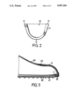
- the safety shoe in accordance with the present invention comprises a steel toe box 10 which has an inwardly turned relatively wide flange 11, a polyethylene liner 20 for cooperating with the steel toe box 10 with the polyethylene liner 20 having a shoulder 7 for mounting and partial contiguous interface between the liner 20 and the toe box 10, and a U-shaped pad 30 for holding the steel toe box 10.
- the thickness of the U-shaped pad (30) is less than the thickness of the middle sole (40).
- the middle sole 40 is provided with a U-shaped cutout 41 for matching and retaining the U-shaped pad 30.
- the front end of the middle sole 40 lies below the flange (11).
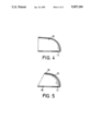
- the flange 11 has a non-uniform width.
- the flange 11 has a larger width at two end portions 12 for ensuring equally good engaging effect and has a smaller width at the central portion 14 for reducing the formation of ruffles at the tip of the shoe during the engagement of the upper 50 to the sole 60.
- the construction of the flange 11 of the steel toe box 10 depends very much on the tensile strength thereof. Due to the continuous formation of the central portion 14, the tensile strength at that portion is larger, and therefore, the flange 11 could have smaller width at the central portion 14. Conversely, the steel toe box 10 is weaker in tensile strength at the two end portions 12 than the central portion 14, and therefore, the flange 11 should have larger width at the two end portions 12 relative to the central portion 14.
- the polyethylene liner 20 is adapted to combine with the steel toe box 10 in a conventional manner which requires no further description.
- the size and shape of the U-shaped pad 30 matches with the size and shape of the U-shaped cutout 41 of the middle sole 40; also, the size and shape of the U-shaped pad 30 substantially matches with the size and shape of the flange 11 of the steel toe box 10.
- the flange 11 of the steel toe box 10 is placed on the U-shaped pad 30 upon assembly.
- the U-shaped pad 30 is made of hardened material and the provision thereof is to take the place of middle sole 40 which is made of softer material so as to protect the middle sole 40 and the sole 60 from abrasion by the steel toe box 10.
- the flange 11 of the steel toe box 10 has a non-uniform thickness.
- the flange 11 has a gradually thinner thickness from the junction portion to the edge, so as to form a wedge shape.
- the wedge-shaped structure of the flange 11 enables the upper 50 to extend over the flange 11 more easily and thus the upper 50 can be glued to the sole 60 readily.
- FIG. 5 it can be seen that another embodiment of the steel toe box 10 in accordance with the present invention has a shortened upper back structure 15.
- the thickness of the upper back portion (15) is uniform and does not taper as the thickness of the flange (11) does.
- the upper back portion 15 of the toe box 10 is shorter than the lower portion 16 thereof.
- Safety shoes having this steel toe box 10 are particularly suitable in the case where only the toe portion of the user is to be protected.
- the steel toe box 10 has a shape where the upper back portion 15 thereof is shortened such that the safety shoes are more comfortable for wearing.
Landscapes
- Chemical & Material Sciences (AREA)
- Engineering & Computer Science (AREA)
- Materials Engineering (AREA)
- Health & Medical Sciences (AREA)
- Epidemiology (AREA)
- General Health & Medical Sciences (AREA)
- Public Health (AREA)
- Footwear And Its Accessory, Manufacturing Method And Apparatuses (AREA)
Abstract
A safety shoe including a steel toe box having an inwardly turned relatively wide flange, the flange having a larger width at two end portions and having a smaller width at a central portion, the flange having a gradually thinner thickness from the junction portion to the edge; a polyethylene liner for cooperating with the toe box; a U-shaped pad made of hardened material having a size and shape substantially matching with a size and shape of the flange of the steel toe box for supporting the steel toe box; and a middle sole having a U-shaped cutout for matching and retaining the U-shaped pad.
Description
The present invention relates generally to safety shoes, and more particularly, to an improved safety shoe.
Conventional steel toe box has inwardly turned relatively wide flange of equal width and thickness. Due to the equal width and thickness of the flange, ruffles formed at the tip of the safety shoe when fixing the upper. When the upper was combined to the sole, the skirt of the upper had to be pulled a considerable distance beyond the flange of the steel toe box. The longer the skirt being pulled, the more the ruffles form. Too many ruffles often resulted in poor combination between the upper and the sole. Generally, the skirt of the upper could not be pulled too much as this caused a bulge to form at the sole and thus caused the shoe unfit for wearing.
The present invention has been arisen to provide a safety shoe which mitigates and/or obviates the afore-mentioned drawbacks of conventional safety shoe.
It is therefore a primary object of the present invention to provide a safety shoe which comprises a steel toe box having a structure which is capable of reducing the formation of ruffles so as to facilitate the engagement of the upper to the sole.
It is also a primary object of the present invention to provide a safety shoe which comprises a steel toe box having a structure which eliminates the need of pulling the skirt of the upper a considerable distance beyond the flange of the steel toe box for combining the upper to the sole.
Another object of the present invention is to provide a safety shoe which comprises a steel toe box which has an inwardly turned relatively wide flange having a larger width at two end portions while having a smaller width at the middle portion.
A further object of the present invention is to provide a safety shoe which comprises a steel toe box which has an inwardly turned relatively wide flange having gradually thinner thickness from the junction portion to the edge.
Still another object of the present invention is to provide a safety shoe which comprises a U-shaped pad which matches the middle sole to facilitate the combination of the safety shoe.
Further objects and advantages of the present invention will be apparent to those skilled in the art upon reading the detailed description provided herein-below, with reference to the attached drawings.
FIG. 1 is an exploded view of a safety shoe in accordance with the present invention;
FIG. 2 is a bottom view of the steel toe box shown in FIG. 1;
FIG. 3 is a partially cutaway lengthwise sectional view of the safety shoe shown in FIG. 1 after assembly;
FIG. 4 is a lengthwise sectional view of the steel toe box shown in FIG. 1; and
FIG. 5 shows a lengthwise sectional view of another embodiment of the steel toe box of the present invention.
Referring to the drawing and initially to FIG. 1, it can be seen that the safety shoe in accordance with the present invention comprises a steel toe box 10 which has an inwardly turned relatively wide flange 11, a polyethylene liner 20 for cooperating with the steel toe box 10 with the polyethylene liner 20 having a shoulder 7 for mounting and partial contiguous interface between the liner 20 and the toe box 10, and a U-shaped pad 30 for holding the steel toe box 10. As shown in FIG. 3, the thickness of the U-shaped pad (30) is less than the thickness of the middle sole (40). The middle sole 40 is provided with a U-shaped cutout 41 for matching and retaining the U-shaped pad 30. As shown in FIG. 5, the front end of the middle sole 40 lies below the flange (11).
Referring further to FIG. 2, it can be seen that the flange 11 has a non-uniform width. The flange 11 has a larger width at two end portions 12 for ensuring equally good engaging effect and has a smaller width at the central portion 14 for reducing the formation of ruffles at the tip of the shoe during the engagement of the upper 50 to the sole 60.
It should be noted that the construction of the flange 11 of the steel toe box 10 depends very much on the tensile strength thereof. Due to the continuous formation of the central portion 14, the tensile strength at that portion is larger, and therefore, the flange 11 could have smaller width at the central portion 14. Conversely, the steel toe box 10 is weaker in tensile strength at the two end portions 12 than the central portion 14, and therefore, the flange 11 should have larger width at the two end portions 12 relative to the central portion 14.
It is this smaller width of flange 11 at the central portion 14 that is responsible for reducing the formation of ruffles at the tip of the shoe during the engagement of the upper 50 to the sole 60.
The polyethylene liner 20 is adapted to combine with the steel toe box 10 in a conventional manner which requires no further description.
Referring next to FIGS. 1 and 3, it can be seen that the size and shape of the U-shaped pad 30 matches with the size and shape of the U-shaped cutout 41 of the middle sole 40; also, the size and shape of the U-shaped pad 30 substantially matches with the size and shape of the flange 11 of the steel toe box 10. The flange 11 of the steel toe box 10 is placed on the U-shaped pad 30 upon assembly. Preferably, the U-shaped pad 30 is made of hardened material and the provision thereof is to take the place of middle sole 40 which is made of softer material so as to protect the middle sole 40 and the sole 60 from abrasion by the steel toe box 10.
Referring next to FIGS. 1 and 4, it can be seen from this sectional view that the flange 11 of the steel toe box 10 has a non-uniform thickness. The flange 11 has a gradually thinner thickness from the junction portion to the edge, so as to form a wedge shape.
The wedge-shaped structure of the flange 11 enables the upper 50 to extend over the flange 11 more easily and thus the upper 50 can be glued to the sole 60 readily.
Referring next to FIG. 5, it can be seen that another embodiment of the steel toe box 10 in accordance with the present invention has a shortened upper back structure 15. As shown in FIG. 5, the thickness of the upper back portion (15) is uniform and does not taper as the thickness of the flange (11) does. In other words, the upper back portion 15 of the toe box 10 is shorter than the lower portion 16 thereof. Safety shoes having this steel toe box 10 are particularly suitable in the case where only the toe portion of the user is to be protected. The steel toe box 10 has a shape where the upper back portion 15 thereof is shortened such that the safety shoes are more comfortable for wearing.
While the present invention has been explained in relation to its preferred embodiment, it is to be understood that various modifications thereof will be apparent to those skilled in the art upon reading this specification. The invention disclosed herein is therefore intended to cover all such modifications as fall within the scope of the appended claims.
Claims (2)
1. A safety shoe comprising:
a steel toe box (10) having an inwardly turned relatively wide flange (11), said flange (11) having a larger width at two opposing respective end portions (12) and having a smaller width at a central portion (14) for increasing the tensile strength of said toe box (10), said flange (11) having a gradually thinner thickness from a junction portion to an edge thereof;
a polyethylene liner (20) having a shoulder for mounting and partial contiguous interface with said steel toe box (10);
a U-shaped pad (30) made of a hardened material having a size and shape substantially matching with a size and shape of said flange (11) of said steel toe box (10) for supporting said steel toe box (10); and,
a middle sole (40) having a front end that lies below a front end of said flange (11) and having a U-shaped cutout (41) for alignment with and retention of said U-shaped pad (30), said middle thickness sole (40) having a thickness that is greater than a thickness of said U-shaped pad (30).
2. A safety shoe as claimed in claim 1, wherein an upper back portion (15) of said steel toe box (10) is shorter than a lower portion (16) thereof and a thickness of said upper back portion (15) is uniform.
Priority Applications (1)
| Application Number | Priority Date | Filing Date | Title |
|---|---|---|---|
| US07/369,121 US5007184A (en) | 1989-06-21 | 1989-06-21 | Safety shoe |
Applications Claiming Priority (1)
| Application Number | Priority Date | Filing Date | Title |
|---|---|---|---|
| US07/369,121 US5007184A (en) | 1989-06-21 | 1989-06-21 | Safety shoe |
Publications (1)
| Publication Number | Publication Date |
|---|---|
| US5007184A true US5007184A (en) | 1991-04-16 |
Family
ID=23454167
Family Applications (1)
| Application Number | Title | Priority Date | Filing Date |
|---|---|---|---|
| US07/369,121 Expired - Fee Related US5007184A (en) | 1989-06-21 | 1989-06-21 | Safety shoe |
Country Status (1)
| Country | Link |
|---|---|
| US (1) | US5007184A (en) |
Cited By (11)
| Publication number | Priority date | Publication date | Assignee | Title |
|---|---|---|---|---|
| US5974697A (en) * | 1998-08-25 | 1999-11-02 | New Tradewell Corporation | Safety shoe |
| US6564477B1 (en) * | 2001-10-30 | 2003-05-20 | Chien-I Wu | Stitch structure of steel-head shoes |
| US6581304B2 (en) | 1999-12-29 | 2003-06-24 | Georgia Boot Llc | Safety shoe |
| US20040159018A1 (en) * | 2003-01-28 | 2004-08-19 | Meibock Antonin A. | Apparatus, system, and method for engaging toes in footwear |
| US20100139121A1 (en) * | 2008-12-09 | 2010-06-10 | Red Wing Shoe Company, Inc. | Molded insole for welted footwear |
| US20100236105A1 (en) * | 2007-12-05 | 2010-09-23 | International de Calzado Ten Pac, S.A. de C.V. | Protective toe cap for industrial footwear |
| AT509582A4 (en) * | 2010-06-23 | 2011-10-15 | Schuetzeneder Thomas | ORTHOPEDIC SAFETY SHOE |
| US20160157552A1 (en) * | 2013-08-07 | 2016-06-09 | Fine Chemical Co., Ltd. | Lightweight foam safety shoes |
| US20160316853A1 (en) * | 2014-04-26 | 2016-11-03 | Mizuno Corporation | Sole Structure for a Sport Shoe |
| US20190387836A1 (en) * | 2018-06-20 | 2019-12-26 | Rocky Brands, Inc. | Footwear with External Safety Toe Cap |
| US12121105B2 (en) | 2005-06-15 | 2024-10-22 | Telfair W. Houston, III | Footwear insert |
Citations (6)
| Publication number | Priority date | Publication date | Assignee | Title |
|---|---|---|---|---|
| US1734531A (en) * | 1923-12-27 | 1929-11-05 | Albert J Ryan | Box-toe piece |
| US2020037A (en) * | 1933-05-01 | 1935-11-05 | Beckwith Mfg Co | Safety shoe |
| US2795868A (en) * | 1955-11-15 | 1957-06-18 | Endicott Johnson Corp | Liner for metal toe boxes |
| US3034235A (en) * | 1959-12-31 | 1962-05-15 | Wolverine Shoe And Tanning Cor | Protective toe structure for shoes |
| GB1098708A (en) * | 1965-03-25 | 1968-01-10 | Desma Werke Gmbh | Improvements in protective footwear comprising steel toe-caps |
| CA839484A (en) * | 1970-04-21 | Fiset Andre | Box toe construction |
-
1989
- 1989-06-21 US US07/369,121 patent/US5007184A/en not_active Expired - Fee Related
Patent Citations (6)
| Publication number | Priority date | Publication date | Assignee | Title |
|---|---|---|---|---|
| CA839484A (en) * | 1970-04-21 | Fiset Andre | Box toe construction | |
| US1734531A (en) * | 1923-12-27 | 1929-11-05 | Albert J Ryan | Box-toe piece |
| US2020037A (en) * | 1933-05-01 | 1935-11-05 | Beckwith Mfg Co | Safety shoe |
| US2795868A (en) * | 1955-11-15 | 1957-06-18 | Endicott Johnson Corp | Liner for metal toe boxes |
| US3034235A (en) * | 1959-12-31 | 1962-05-15 | Wolverine Shoe And Tanning Cor | Protective toe structure for shoes |
| GB1098708A (en) * | 1965-03-25 | 1968-01-10 | Desma Werke Gmbh | Improvements in protective footwear comprising steel toe-caps |
Non-Patent Citations (4)
| Title |
|---|
| UK Patent Application GB 2138272A, pub. 10 1984, 36/72R, Smith. * |
| UK Patent Application GB 2138272A, pub. 10-1984, 36/72R, Smith. |
| UK Patent Application GB 2176690A, pub. 01 1987, 36/72 R, Durey. * |
| UK Patent Application GB 2176690A, pub. 01-1987, 36/72 R, Durey. |
Cited By (15)
| Publication number | Priority date | Publication date | Assignee | Title |
|---|---|---|---|---|
| US5974697A (en) * | 1998-08-25 | 1999-11-02 | New Tradewell Corporation | Safety shoe |
| US6581304B2 (en) | 1999-12-29 | 2003-06-24 | Georgia Boot Llc | Safety shoe |
| US6564477B1 (en) * | 2001-10-30 | 2003-05-20 | Chien-I Wu | Stitch structure of steel-head shoes |
| US20040159018A1 (en) * | 2003-01-28 | 2004-08-19 | Meibock Antonin A. | Apparatus, system, and method for engaging toes in footwear |
| US6954997B2 (en) * | 2003-01-28 | 2005-10-18 | Kor Hockey Ltd. | Apparatus, system, and method for engaging toes in footwear |
| US12121105B2 (en) | 2005-06-15 | 2024-10-22 | Telfair W. Houston, III | Footwear insert |
| US20100236105A1 (en) * | 2007-12-05 | 2010-09-23 | International de Calzado Ten Pac, S.A. de C.V. | Protective toe cap for industrial footwear |
| US8621765B2 (en) * | 2008-12-09 | 2014-01-07 | Red Wing Shoe Company, Inc. | Molded insole for welted footwear |
| US20100139121A1 (en) * | 2008-12-09 | 2010-06-10 | Red Wing Shoe Company, Inc. | Molded insole for welted footwear |
| AT509582A4 (en) * | 2010-06-23 | 2011-10-15 | Schuetzeneder Thomas | ORTHOPEDIC SAFETY SHOE |
| AT509582B1 (en) * | 2010-06-23 | 2011-10-15 | Schuetzeneder Thomas | ORTHOPEDIC SAFETY SHOE |
| US20160157552A1 (en) * | 2013-08-07 | 2016-06-09 | Fine Chemical Co., Ltd. | Lightweight foam safety shoes |
| US20160316853A1 (en) * | 2014-04-26 | 2016-11-03 | Mizuno Corporation | Sole Structure for a Sport Shoe |
| US9901137B2 (en) * | 2014-04-26 | 2018-02-27 | Mizuno Corporation | Sole structure for a sport shoe |
| US20190387836A1 (en) * | 2018-06-20 | 2019-12-26 | Rocky Brands, Inc. | Footwear with External Safety Toe Cap |
Similar Documents
| Publication | Publication Date | Title |
|---|---|---|
| US5007184A (en) | Safety shoe | |
| US4995174A (en) | Shoe with detachable toe cover | |
| US5313719A (en) | Shoe shield | |
| US4449306A (en) | Running shoe sole construction | |
| US12495859B2 (en) | Footwear | |
| US5079857A (en) | Shoe having a detachable heel | |
| US3939583A (en) | Ice hockey boot | |
| US4638574A (en) | Removable shoe protector | |
| US2362010A (en) | Shoe | |
| ITTV940048U1 (en) | TAB FOR INTERNAL SKI BOOTS | |
| US6895695B1 (en) | Shoe structure | |
| US2935799A (en) | Reinforced heel with replaceable tap | |
| CA2214748A1 (en) | Quarter for skate boot | |
| US4357763A (en) | Sole assembly for a sports shoe | |
| US5974697A (en) | Safety shoe | |
| US3159928A (en) | Interchangeable heel for a shoe | |
| JPH07313629A (en) | Fin for swimming | |
| US1954761A (en) | Calk structure | |
| US1996215A (en) | Foot corrective shoe construction | |
| ITTV990005A1 (en) | SUPPORT STRUCTURE PARTICULARLY FOR FOOTWEAR. | |
| US3094793A (en) | Means for securing top lifts to shoe heels | |
| US3195245A (en) | Women's boot heel construction | |
| US1995831A (en) | Shoe | |
| EP0152017A1 (en) | Heelplate structure particularly for ski boots | |
| US3243900A (en) | Reinforced heel and tap |
Legal Events
| Date | Code | Title | Description |
|---|---|---|---|
| FPAY | Fee payment |
Year of fee payment: 4 |
|
| REMI | Maintenance fee reminder mailed | ||
| LAPS | Lapse for failure to pay maintenance fees | ||
| FP | Lapsed due to failure to pay maintenance fee |
Effective date: 19990416 |
|
| STCH | Information on status: patent discontinuation |
Free format text: PATENT EXPIRED DUE TO NONPAYMENT OF MAINTENANCE FEES UNDER 37 CFR 1.362 |