US5005923A - Limit switch assembly for mobile storage apparatus - Google Patents
Limit switch assembly for mobile storage apparatus Download PDFInfo
- Publication number
- US5005923A US5005923A US07/491,256 US49125690A US5005923A US 5005923 A US5005923 A US 5005923A US 49125690 A US49125690 A US 49125690A US 5005923 A US5005923 A US 5005923A
- Authority
- US
- United States
- Prior art keywords
- switch
- rod means
- storage unit
- cam
- unit
- Prior art date
- Legal status (The legal status is an assumption and is not a legal conclusion. Google has not performed a legal analysis and makes no representation as to the accuracy of the status listed.)
- Expired - Lifetime
Links
- 230000000712 assembly Effects 0.000 claims description 10
- 238000000429 assembly Methods 0.000 claims description 10
- 230000002441 reversible effect Effects 0.000 claims description 3
- 230000001133 acceleration Effects 0.000 description 12
- 238000009434 installation Methods 0.000 description 3
- 239000004020 conductor Substances 0.000 description 2
- 238000003825 pressing Methods 0.000 description 2
- 238000013459 approach Methods 0.000 description 1
- 230000001934 delay Effects 0.000 description 1
- 238000010586 diagram Methods 0.000 description 1
- 230000000694 effects Effects 0.000 description 1
- 230000000977 initiatory effect Effects 0.000 description 1
- 239000002184 metal Substances 0.000 description 1
- 238000000034 method Methods 0.000 description 1
- 230000000644 propagated effect Effects 0.000 description 1
- 238000004904 shortening Methods 0.000 description 1
Images
Classifications
-
- A—HUMAN NECESSITIES
- A47—FURNITURE; DOMESTIC ARTICLES OR APPLIANCES; COFFEE MILLS; SPICE MILLS; SUCTION CLEANERS IN GENERAL
- A47B—TABLES; DESKS; OFFICE FURNITURE; CABINETS; DRAWERS; GENERAL DETAILS OF FURNITURE
- A47B53/00—Cabinets or racks having several sections one behind the other
- A47B53/02—Cabinet systems, e.g. consisting of cabinets arranged in a row with means to open or close passages between adjacent cabinets
-
- H—ELECTRICITY
- H01—ELECTRIC ELEMENTS
- H01H—ELECTRIC SWITCHES; RELAYS; SELECTORS; EMERGENCY PROTECTIVE DEVICES
- H01H15/00—Switches having rectilinearly-movable operating part or parts adapted for actuation in opposite directions, e.g. slide switch
- H01H15/02—Details
- H01H15/06—Movable parts; Contacts mounted thereon
- H01H15/10—Operating parts
- H01H15/102—Operating parts comprising cam devices
- H01H15/107—Operating parts comprising cam devices actuating conventional selfcontained microswitches
-
- H—ELECTRICITY
- H01—ELECTRIC ELEMENTS
- H01H—ELECTRIC SWITCHES; RELAYS; SELECTORS; EMERGENCY PROTECTIVE DEVICES
- H01H15/00—Switches having rectilinearly-movable operating part or parts adapted for actuation in opposite directions, e.g. slide switch
- H01H15/02—Details
- H01H15/06—Movable parts; Contacts mounted thereon
- H01H15/10—Operating parts
- H01H15/14—Operating parts adapted for actuation at a limit or other predetermined position in the path of a body, the relative movement of switch and body being primarily for a purpose other than the actuation of the switch, e.g. door switch, limit switch, floor-levelling switch of a lift
Definitions
- This invention pertains to movable storage systems wherein a series of storage units having shelves or bins are supported on wheeled carriages to provide for moving the units on tracks to create an access aisle between any two of the units and to establish the others in close side-by-side relationship to minimize the amount of floor space required for the units.
- the invention resides in a new limit switch assembly which is capable of governing the time at which acceleration and deceleration of the units occurs as they are moved in series to close a presently open aisle and to thereby create the space for opening a presently closed aisle between units.
- Storage unit systems customarily have several mobile storage units arranged to run on tracks between two spaced apart stationary storage units.
- the number of mobile storage units in the system is usually one less than the number which would be required to fill all of the space between the fixed storage units so that there is always one open aisle in existence which can be entered by a person to gain access to shelves on storage units adjacent each side of the aisle.
- pressing the push button issues a command signal which is interpreted by a microprocessor in a controller on each of the mobile storage units in a manner that determines which way the storage units should be driven in sequence to close the open aisle and open the presently closed aisle.
- the mobile storage unit which is adjacent the open aisle will be the first one to begin moving toward closing that aisle.
- the first unit to move would have to move a substantial distance before the second unit would begin to move and there would be subsequent corresponding delays from unit to unit so that the time required to close one aisle and open another by shifting the mobile units therebetween was not minimized.
- a spring biased rod usually extends outwardly from the switch housing into an open aisle, for instance, such that when the first movable unit adjacent the open aisle approaches a stationary mobile storage unit or a unit at the end of the series of mobile units, the rod strikes a stop on the stationary unit and begins to retract into the limit switch.
- an actuator on the rod actuates the limit switch, that is, it opens the limit switch and brings about deenergization of the driving motor on that particular storage unit.
- the moving unit coasts for a short distance after the limit switch opened.
- the prior art limit switch operating rod on the mobile storage unit adjacent the open aisle would, of course, extend into the free space between this first unit that would have to be moved and a stationary unit. With the operating rod extended, the limit switch on the first unit adjacent the open aisle would be in closed circuit condition so that it could move in response to the controller on this unit interpreting the signal produced by the use of the push button next to the closed aisle as a command to start moving all of the mobile units in the appropriate direction to close the open aisle and open the closed aisle.
- the first unit had to complete the acceleration interval before the unit moved far enough away from the next trailing unit to permit its limit switch to close and begin an acceleration interval.
- the first unit would have to move about 4" before the next trailing unit would begin to move and this kind of delay accumulated all the way down the line to the last unit that would begin movement adjacent the place where an aisle was to be opened.
- the gap between units was substantial and total time for opening an aisle was not minimized.
- One object of the invention is to provide a new limit switch assembly which, in conjunction with closing an aisle, allows the mobile storage unit that follows the unit which begins to move first into the open aisle space to begin moving an instant after the first mobile unit begins to move.
- the mobile unit following the first unit begins to accelerate up to speed while the leading or first unit next to the open aisle is still accelerating.
- the gap between the first and next following unit can be very small.
- the third unit begins to accelerate while the second unit is still accelerating so it follows the second unit very closely. This action is propagated all the way down the line to the series of mobile storage units.
- the new limit switch assembly provides for the units starting in a controlled acceleration mode such that they start moving smoothly and in a short distance they reach full operating speed.
- the new limit switch assembly also provides for controlled deceleration of the movable storage units before they stop.
- Another objective of the new switch assembly is to bring about smooth deceleration of the units over an interval such as by way of example and not limitation, over a distance of 4" of storage unit travel before events in the limit switch assembly occur which allow the mobile unit to come to a complete stop.
- This objective is achieved by using two switches in each limit switch assembly and by actuating these limit switches by means of a cam which is mounted to the switch operating rod.
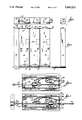
- FIG. 1 is a diagram of a plurality of movable storage units among which some of the units are in contact with each other and other units are separated from each other to provide an aisle to give the user access to the shelves or bins on the interfacing sides of the units;
- FIG. 3 depicts the new limit switch assembly which contains two limit switches and has its switch operating rod presently retracted or pushed into the switch assembly housing as is the case when the rod of a limit switch on one of the mobile storage units has abutted a mobile or fixed storage unit;
- FIG. 4 shows the new limit switch assembly with its operating rod fully extended from the housing as would be the case if the switch assembly in this FIGURE were on a storage unit which is adjacent an open aisle.
- FIG. 1 is a front elevational diagrammatic view of several storage units that are arranged to move alternately and selectively to the left and right to establish an access aisle between them at the command of an user.
- FIG. 1 shows the upright end walls of these units.
- the mobile units are arranged between stationary units 13 and 14 which could be the walls of a room as well.
- the mobile units run on floor mounted tracks which are generally designated by the numeral 15.
- the mobile storage units are supported on carriages, not shown, which have a set of four wheels. Typical two wheels 17 and 18 of the set which are visible on unit 10 run on tracks 15.
- the motor 16 is symbolically coupled in driving relation to the shafts for these wheels by means of closed loop drive chains such as the one marked 19.
- FIG. 1 there is an open aisle marked 20 in FIG. 1 between mobile storage unit 12 and stationary unit 14.
- controller boxes 24 There is a box such as the one marked 24 and shown in dashed lines mounted behind the end wall of each one of the mobile storage units 10-12. These boxes contain electrical components which comprise controllers for the motors on the respective mobile storage units.
- the patent cited above illustrates the kind of control equipment that may be contained in controller boxes 24.
- the user always uses a push button assembly next to a space between storage units which the user desires to convert from a narrow space to a user accessible aisle. For instance, if the user desires to convert narrow space 23 into a full aisle, the user would press a push button in push button assembly 28.
- This provides a common signal to the controller 24 on storage unit 10 which the controller would interpret as a command to move all units to the right to open the aisle.
- this command is also interpreted by the controllers 24 in the other units in a manner which will result in the storage units moving in sequence and in the proper direction to bring about opening of the selected aisle.
- issuing the command by operation of push button 28 would result in storage unit 12, adjacent open aisle 20, beginning to drive to the right towards stationary unit 14 to close that aisle.
- the trailing or following units 11 and 10 would also move to the right by the same amount that the leading storage unit 12 has moved to bring about opening of aisle 23.
- FIGS. 1 and 2 show the new limit switch assemblies mounted on top of the mobile storage units. All limit switch assemblies are identical. There are two limit switch assemblies 35 and 36 on mobile storage unit 10. There is one limit switch assembly 37 on mobile storage unit 11 and one assembly 38 on storage unit 12. Each of the limit switch assemblies has a plunger or switch operating rod such as the one marked 39 extending outwardly from the limit switch housing into the open space constituted by aisle 20. If mobile unit 12 moves toward stationary unit 14, rod 39 will strike a stop element 40 on stationary unit 14 eventually and rod 39 will be retracted or pushed into the housing of limit switch assembly 38 to perform some switch operating functions as will be explained shortly hereinafter. There are stops corresponding to stop 40 on stationary unit 13 and mobile units 11 and 12 in this particular installation.
- the limit switch assembly comprises a mounting base member in the form of a sheet metal housing 45 which has flanges 46 and 47 extending from it.
- Typical flange 46 has slots such as the one marked 48 which provide for clamping the housing on top of a storage unit by means of four screws such as the one marked 49.
- the slots 48 allow the housing to be positioned adjustably so that the limit switch acts at the proper time during movement of the storage units.
- a switch operating plunger 51 extends from limit switch LS1 which is typical.
- Switch LS1 in FIG. 3 is not actuated and is in its normally open circuited state.
- Switch LS2 in FIG. 3 is a normally closed switch but it is presently actuated by its operating lever 53 so that LS2 is presently open circuited.
- a cylindrical cam element 57 is fastened to switch operating rod 39. Truncated conical cam surfaces 58 and 59 are formed on cylindrical element 57.
- cam surface 59 has actuated lever 53 as depicted in FIG. 3 with the result that normally closed switch LS2 is presently open circuited in addition to switch LS1 being open.
- a pin 60 extends from cam cylinder 57 and one end of a coil spring 61 is hooked onto pin 60 while the other end 62 of the spring is hooked into an appropriate hole in the wall of the limit switch housing 45.
- a stop element in the form of a snap ring 65 is fastened to switch operating rod 39 to assure that cam surface 58 is actuating LS1 when the spring has pulled the rod to its left limit and to prevent the spring from pulling the rod out of the housing.
- the switch operating rod or plunger 39 is in retracted condition. That is, it is pushed back into the housing by reason of its tip 63 having run into a stop 40 which may be a stop that is mounted to either of the stationary units 13 or 14 or a corresponding stop that is mounted to one of the mobile units that is adjacent the mobile unit on which the limit switch in FIG. 3 is mounted.
- a stop 40 which may be a stop that is mounted to either of the stationary units 13 or 14 or a corresponding stop that is mounted to one of the mobile units that is adjacent the mobile unit on which the limit switch in FIG. 3 is mounted.
- the conductors leading from the limit switches LS1 and LS2 comprise a cable 64 which runs through an insulating bushing 66 and, although the conductors are shown interrupted in FIG. 3, they do connect into appropriate places in the circuitry contained in controller boxes 24 in the mobile storage units.
- mobile storage unit 12 begins to drive to the right.
- unit 12 accelerates for a short interval of about 2 seconds in this example after which its motor and the unit reach full operating speed.
- No change in the running condition takes place for a while but eventually limit switch operating rod 39 will run into stop 40 on stationary storage unit 14 so as to bring about retraction of rod 39 into the housing of limit switch assembly 38.
- the switch assembly is in the condition of the assembly depicted in FIG. 4. A moment after the tip of the rod meets the stop 40, cam surface 58 which is presently holding LS1 in closed circuit condition moves to cause switch LS1 to change to open circuit condition.
- deceleration occurs over a 3.75" span of movement of the storage unit. Acceleration also occurs while the storage unit was traversing its first 3.75" of travel. Shortening and lengthening the cam cylinder 57 would, respectively, increase and decrease deceleration time and distance.
- the first or leading storage unit 12 will lead the trailing or second storage unit 11, due to the first storage unit coming up to full speed sooner, sufficiently for switch operating rod 39 of limit switch assembly 37 to extend partially under the influence of coil spring 61.
- Cam surface 58 thereby actuates operating lever 52 of LS1 in which case the circuit in LS1 closes as illustrated in FIG. 4.
- the next thing that happens is for push rod 39, of limit switch assembly 38 to be further retracted by running against the stop 40 on the leading or first mobile storage unit 12 in which case the cam surface 58 departs from the switch operating lever 52 and the LS1 switching circuit opens.
- Mobile storage unit 11 would be the first one to move when the command is given to open aisle 20 and concomitantly close aisle 22. At the outset the controller 24 would ignore the condition of the switches LS1 and LS2 in the limit switch assemblies 37 and 38 of storage units 11 and 12, respectively. When the switch assembly 36 of mobile storage unit 10 which will not move at all in connection with opening aisle 20 and closing aisle 22.
Landscapes
- Warehouses Or Storage Devices (AREA)
Abstract
Description
Claims (8)
Priority Applications (3)
| Application Number | Priority Date | Filing Date | Title |
|---|---|---|---|
| US07/491,256 US5005923A (en) | 1990-03-09 | 1990-03-09 | Limit switch assembly for mobile storage apparatus |
| CA002017899A CA2017899C (en) | 1990-03-09 | 1990-05-30 | Limit switch assembly for mobile storage apparatus |
| US07/638,070 US5044703A (en) | 1990-03-09 | 1991-01-07 | Limit switch assembly for mobile storage apparatus |
Applications Claiming Priority (1)
| Application Number | Priority Date | Filing Date | Title |
|---|---|---|---|
| US07/491,256 US5005923A (en) | 1990-03-09 | 1990-03-09 | Limit switch assembly for mobile storage apparatus |
Publications (1)
| Publication Number | Publication Date |
|---|---|
| US5005923A true US5005923A (en) | 1991-04-09 |
Family
ID=23951417
Family Applications (1)
| Application Number | Title | Priority Date | Filing Date |
|---|---|---|---|
| US07/491,256 Expired - Lifetime US5005923A (en) | 1990-03-09 | 1990-03-09 | Limit switch assembly for mobile storage apparatus |
Country Status (2)
| Country | Link |
|---|---|
| US (1) | US5005923A (en) |
| CA (1) | CA2017899C (en) |
Cited By (8)
| Publication number | Priority date | Publication date | Assignee | Title |
|---|---|---|---|---|
| US5401090A (en) * | 1992-11-06 | 1995-03-28 | Spacesaver Corporation | Mechanical automatic aisle lock |
| EP0678884A1 (en) * | 1994-04-21 | 1995-10-25 | MANNESMANN Aktiengesellschaft | Switch actuation unit |
| EP1125523A1 (en) * | 2000-02-17 | 2001-08-22 | Heidrich, Helmut, Steuerungsanlagenbau GmbH | A storage device made from a plurality of sliding cupboards |
| US20070252491A1 (en) * | 2006-04-27 | 2007-11-01 | Montel Inc. | Braking system for mobile storage unit |
| US20080303387A1 (en) * | 2007-06-05 | 2008-12-11 | Haubenschild Mark P | Mobile High Bay Storage System Having Vehicle Guidance System |
| US20110200452A1 (en) * | 2010-02-18 | 2011-08-18 | Raymond Ascord Noel | Multiple switch float switch apparatus |
| US20120312397A1 (en) * | 2010-02-18 | 2012-12-13 | Raymond Ascord Noel | Multiple switch float switch apparatus |
| CN104269288A (en) * | 2014-09-09 | 2015-01-07 | 山东钢铁股份有限公司 | Installation device and method for proximity switch |
Citations (7)
| Publication number | Priority date | Publication date | Assignee | Title |
|---|---|---|---|---|
| US3676625A (en) * | 1971-04-09 | 1972-07-11 | Leland F Blatt | Dual plunger actuated sealed combination safety and interlock switch mechanism |
| US3857593A (en) * | 1973-05-30 | 1974-12-31 | G Lening | Gate latch assembly |
| US3957322A (en) * | 1975-03-06 | 1976-05-18 | Estey Corporation | Control means for selectively shifting storage units |
| US4107490A (en) * | 1976-03-04 | 1978-08-15 | Francis Xavier Keane | Hospital beds |
| US4215257A (en) * | 1978-11-20 | 1980-07-29 | Otto Engineering, Inc. | Precision toggle switch |
| US4678877A (en) * | 1985-10-23 | 1987-07-07 | Alsthom | Operating mechanism for a circuit-breaker, and a circuit-breaker fitted with the mechanism |
| US4783618A (en) * | 1982-12-27 | 1988-11-08 | Acme Visible Records, Inc | Apparatus and method for controlling apparatus including a plurality of guided units |
-
1990
- 1990-03-09 US US07/491,256 patent/US5005923A/en not_active Expired - Lifetime
- 1990-05-30 CA CA002017899A patent/CA2017899C/en not_active Expired - Fee Related
Patent Citations (7)
| Publication number | Priority date | Publication date | Assignee | Title |
|---|---|---|---|---|
| US3676625A (en) * | 1971-04-09 | 1972-07-11 | Leland F Blatt | Dual plunger actuated sealed combination safety and interlock switch mechanism |
| US3857593A (en) * | 1973-05-30 | 1974-12-31 | G Lening | Gate latch assembly |
| US3957322A (en) * | 1975-03-06 | 1976-05-18 | Estey Corporation | Control means for selectively shifting storage units |
| US4107490A (en) * | 1976-03-04 | 1978-08-15 | Francis Xavier Keane | Hospital beds |
| US4215257A (en) * | 1978-11-20 | 1980-07-29 | Otto Engineering, Inc. | Precision toggle switch |
| US4783618A (en) * | 1982-12-27 | 1988-11-08 | Acme Visible Records, Inc | Apparatus and method for controlling apparatus including a plurality of guided units |
| US4678877A (en) * | 1985-10-23 | 1987-07-07 | Alsthom | Operating mechanism for a circuit-breaker, and a circuit-breaker fitted with the mechanism |
Cited By (13)
| Publication number | Priority date | Publication date | Assignee | Title |
|---|---|---|---|---|
| US5401090A (en) * | 1992-11-06 | 1995-03-28 | Spacesaver Corporation | Mechanical automatic aisle lock |
| EP0678884A1 (en) * | 1994-04-21 | 1995-10-25 | MANNESMANN Aktiengesellschaft | Switch actuation unit |
| US5579899A (en) * | 1994-04-21 | 1996-12-03 | Mannesmann Aktiengesellschaft | Switch actuating unit |
| EP1125523A1 (en) * | 2000-02-17 | 2001-08-22 | Heidrich, Helmut, Steuerungsanlagenbau GmbH | A storage device made from a plurality of sliding cupboards |
| US7645000B2 (en) * | 2006-04-27 | 2010-01-12 | Montel Inc. | Braking system for mobile storage unit |
| US20070252491A1 (en) * | 2006-04-27 | 2007-11-01 | Montel Inc. | Braking system for mobile storage unit |
| US20080303387A1 (en) * | 2007-06-05 | 2008-12-11 | Haubenschild Mark P | Mobile High Bay Storage System Having Vehicle Guidance System |
| US7829838B2 (en) | 2007-06-05 | 2010-11-09 | Spacesaver Corporation | Mobile high bay storage system having vehicle guidance system |
| US20110200452A1 (en) * | 2010-02-18 | 2011-08-18 | Raymond Ascord Noel | Multiple switch float switch apparatus |
| US20120312397A1 (en) * | 2010-02-18 | 2012-12-13 | Raymond Ascord Noel | Multiple switch float switch apparatus |
| US8430641B2 (en) * | 2010-02-18 | 2013-04-30 | Raymond Ascord Noel | Multiple switch float switch apparatus |
| US8985964B2 (en) * | 2010-02-18 | 2015-03-24 | Raymond Ascord Noel | Multiple switch float switch apparatus |
| CN104269288A (en) * | 2014-09-09 | 2015-01-07 | 山东钢铁股份有限公司 | Installation device and method for proximity switch |
Also Published As
| Publication number | Publication date |
|---|---|
| CA2017899C (en) | 1999-12-21 |
| CA2017899A1 (en) | 1991-09-09 |
Similar Documents
| Publication | Publication Date | Title |
|---|---|---|
| JP4617310B2 (en) | Furniture with movable furniture parts | |
| US5005923A (en) | Limit switch assembly for mobile storage apparatus | |
| US3398484A (en) | Car door actuator | |
| US5044703A (en) | Limit switch assembly for mobile storage apparatus | |
| US3139994A (en) | Mechanical load handling, transfer and storage equipment | |
| US3646613A (en) | Automatic carrying system | |
| EP0627677B1 (en) | Control signal transmission to a vehicle with crash sensing switches | |
| DE2032765A1 (en) | Automatic control device, especially for a sliding door, which is driven by a linear motor | |
| DE2626780A1 (en) | METHOD AND DEVICE FOR CONTROLLING THE CHANGE OF POSITION OF INDEPENDENT DEVICES FOR PULLING OVER OBJECTS | |
| EP0246770A2 (en) | Force actuators | |
| CN113815514B (en) | Combined range-increasing type high-speed electromagnetic emission system | |
| US3554325A (en) | Motor control mechanism | |
| DE2309178A1 (en) | AUTOMATIC WAREHOUSE EQUIPMENT | |
| US2688718A (en) | Motor reversing switch and system | |
| US3393814A (en) | Detecting device for improperly positioned loads in multi-level storage frame of a waehousing system | |
| US3401926A (en) | Carriage control means for cloth laying machines | |
| JPS5940541B2 (en) | Ingotsushijisouchi | |
| CN220853300U (en) | Multistage push-pull mechanism | |
| JPH05332066A (en) | Automatic door opening and closing device | |
| CN214378187U (en) | Electromagnetic quick mechanism and quick mechanical switch | |
| US2769923A (en) | Automatic ignition control switch | |
| US2999423A (en) | Electric drives for photographic enlarging and reproducing apparatus | |
| JPH04193050A (en) | Coil inserter having single drive mechanism | |
| JPH0631951Y2 (en) | Mobile shelf equipment | |
| SU772969A1 (en) | Apparatus for controlling the travelling gear of gantry-crane with pneumatic drive |
Legal Events
| Date | Code | Title | Description |
|---|---|---|---|
| AS | Assignment |
Owner name: SPACESAVER CORPORATION, A WI CORP. Free format text: ASSIGNMENT OF ASSIGNORS INTEREST.;ASSIGNOR:DAHNERT, DEAN L.;REEL/FRAME:005255/0830 Effective date: 19900306 |
|
| STCF | Information on status: patent grant |
Free format text: PATENTED CASE |
|
| FPAY | Fee payment |
Year of fee payment: 4 |
|
| FPAY | Fee payment |
Year of fee payment: 8 |
|
| FEPP | Fee payment procedure |
Free format text: PAYOR NUMBER ASSIGNED (ORIGINAL EVENT CODE: ASPN); ENTITY STATUS OF PATENT OWNER: LARGE ENTITY |
|
| FEPP | Fee payment procedure |
Free format text: PAT HOLDER NO LONGER CLAIMS SMALL ENTITY STATUS, ENTITY STATUS SET TO UNDISCOUNTED (ORIGINAL EVENT CODE: STOL); ENTITY STATUS OF PATENT OWNER: LARGE ENTITY |
|
| REFU | Refund |
Free format text: REFUND - PAYMENT OF MAINTENANCE FEE, 12TH YR, SMALL ENTITY (ORIGINAL EVENT CODE: R285); ENTITY STATUS OF PATENT OWNER: LARGE ENTITY |
|
| FPAY | Fee payment |
Year of fee payment: 12 |
|
| AS | Assignment |
Owner name: U.S. BANK NATIONAL ASSOCIATION,MISSOURI Free format text: SECURITY AGREEMENT;ASSIGNOR:SPACESAVER CORPORATION;REEL/FRAME:024233/0039 Effective date: 20100407 Owner name: U.S. BANK NATIONAL ASSOCIATION, MISSOURI Free format text: SECURITY AGREEMENT;ASSIGNOR:SPACESAVER CORPORATION;REEL/FRAME:024233/0039 Effective date: 20100407 |