US4999533A - Dynamoelectric machine - Google Patents

Dynamoelectric machine Download PDF

Info

Publication number
US4999533A
US4999533A US07/412,855 US41285589A US4999533A US 4999533 A US4999533 A US 4999533A US 41285589 A US41285589 A US 41285589A US 4999533 A US4999533 A US 4999533A
Authority
US
United States
Prior art keywords
rotor
housing member
stator
core
stator core
Prior art date
Legal status (The legal status is an assumption and is not a legal conclusion. Google has not performed a legal analysis and makes no representation as to the accuracy of the status listed.)
Expired - Fee Related
Application number
US07/412,855
Inventor
James L. King
Robert E. Lykes
Current Assignee (The listed assignees may be inaccurate. Google has not performed a legal analysis and makes no representation or warranty as to the accuracy of the list.)
AO Smith Corp
Original Assignee
AO Smith Corp
Priority date (The priority date is an assumption and is not a legal conclusion. Google has not performed a legal analysis and makes no representation as to the accuracy of the date listed.)
Filing date
Publication date
Application filed by AO Smith Corp filed Critical AO Smith Corp
Priority to US07/412,855 priority Critical patent/US4999533A/en
Assigned to A. O. SMITH CORPORATION reassignment A. O. SMITH CORPORATION ASSIGNMENT OF ASSIGNORS INTEREST. Assignors: KING, JAMES L., LYKES, ROBERT E.
Application granted granted Critical
Publication of US4999533A publication Critical patent/US4999533A/en
Anticipated expiration legal-status Critical
Expired - Fee Related legal-status Critical Current

Links

Images

Classifications

    • HELECTRICITY
    • H02GENERATION; CONVERSION OR DISTRIBUTION OF ELECTRIC POWER
    • H02KDYNAMO-ELECTRIC MACHINES
    • H02K5/00Casings; Enclosures; Supports
    • H02K5/04Casings or enclosures characterised by the shape, form or construction thereof
    • H02K5/12Casings or enclosures characterised by the shape, form or construction thereof specially adapted for operating in liquid or gas
    • H02K5/128Casings or enclosures characterised by the shape, form or construction thereof specially adapted for operating in liquid or gas using air-gap sleeves or air-gap discs
    • HELECTRICITY
    • H02GENERATION; CONVERSION OR DISTRIBUTION OF ELECTRIC POWER
    • H02KDYNAMO-ELECTRIC MACHINES
    • H02K15/00Processes or apparatus specially adapted for manufacturing, assembling, maintaining or repairing of dynamo-electric machines
    • H02K15/14Casings; Enclosures; Supports

Definitions

  • This invention relates to a dynamoelectric machine and particularly to an electric motor adapted to be mounted within a separate enclosure.
  • a rotary dynamoelectric machine such as a rotary motor
  • a motor is mounted within a separate housing such as a fan housing with the motor shaft coupled to drive a fan blade.
  • the motor includes an outer annular stator unit of any known or suitable construction.
  • a rotor unit is rotatably mounted within the stator.
  • a standard conventional motor will include an annular stator core of the stator unit fixedly mounted in any suitable manner within a heavy outer tubular motor frame.
  • the frame projects axially from the ends of the stator core beyond the ends of the stator winding.
  • the ends of the frame are machined and corresponding machined end plates are interconnected to the ends of the motor frame as by through bolts or other securement devices.
  • Rotor bearings are secured one each within each of the end plates in appropriate alignment.
  • the rotor shaft is journaled in the bearings with the rotor core aligned with the stator core.
  • the machined frame ends and end plates accurately locate the bearings to support the rotor core and the stator core with air gap therebetween to permit free rotation of the rotor core.
  • the air gap between the rotor core and the stator core must be maintained within specified clearance limits.
  • efficient motor design requires minimizing of the air gap between the stator and the rotor. Strong magnetic forces are created between the cores of the stator unit and the rotor unit and a substantial frame is necessary to hold and maintain the necessary air gap between the rotor core and stator core.
  • radial side loads may be applied to the shaft by the driven load creating even larger forces on the rotor support structure.
  • the magnetic forces plus the radial side load forces can result in bearing radial loads of several hundred pounds. This requires rigid bearing supports, and a corresponding supporting frame, to firmly support the rotor within the stator without danger of the rotor bridging the air gap and damaging the members.
  • the motor frame is not necessary because the motor is housed within a separate housing.
  • the standard motor with the motor frame can be used.
  • a frameless motor can be used wherein the stator unit can be mounted directly to the frame or a mounting base of the driven element. The rotor unit is then appropriately supported by appropriate bearing structures interconnected to each other and/or to the driven element support structure.
  • U.S. Pat. No. 4,244,099 which issued Jan. 13, 1981 discloses an electric motor adapted to be mounted as a part of a gear train housing.
  • the motor consists of an outer annular stator unit within an outer main frame and a separate enclosed rotor unit which extends through the stator and extends therefrom for mounting of the rotor with a press fit within an opening in the gear frame.
  • the rotor is supported by the opening in the base wall of the housing while the stator unit is supported and located within an enlarged recess in the housing.
  • 4,598,218 and 4,510,679 disclose similar high speed rotors where the rotor core and winding is protected by an encircling protective shell which closely fits and is secured about the core.
  • Special shaft units project outwardly from the opposite ends of the core for mounting in separate bearing assemblies mounted in separate supports of the outer enclosure structure.
  • the present invention is related to a frameless motor having an enclosed rotor unit closely fitted and secured to a stator core unit and having extended integrated bearing units therein for rotatably supporting of the rotor unit.
  • the rotor unit is mounted within an outer tubular enclosure, which includes a relatively thin wall tubular member encircling the rotor core and projecting axially from the opposite end of the core. The ends of the tubular member are closed by bearing walls having appropriate annular rotary bearings secured therein.
  • the rotor shaft is journaled in the bearings to define a frameless motor.
  • a relatively thin metal tube is formed of a non-magnetic metal such as stainless steel and has an outside diameter slightly in excess or greater than the inside diameter of the stator core.
  • the tube is press fitted into the stator core with an interference or press fit which preferably forms the sole support for the metal tube.
  • the length of the tube is substantially greater than the axial length of the stator core and the axially length of the rotor.
  • a similar metal end plate is secured within each end of the metal tube with rotary bearings secured to the center of each end plate. The end plates are fixedly secured to the metal tube in any suitable manner including a press fit.
  • the rotor unit with the end bearing plates coupled to the rotor shaft can be preassembled and then assembled into the metal tube.
  • the end plates are secured to the opposite ends of the metal tube.
  • the rotor assembly is then press fitted into the core of a prewound stator unit to create a complete and frameless motor which is subsequently assembled to any suitable support or housing.
  • the assembly can also be made by press fitting of the tube within the stator core, securing an end plate to one end of the tube, assemblying the rotor unit into the tube and the one plate, and finally securing the second plate to the tube and the rotor shaft.
  • the motor of this invention overcomes many of the disadvantages and objections presently associated with the specifications requiring frameless electric motors or other dyamoelectric motors. Although shown and uniquely adapted to electric motors, it is obviously equally applicable to any other dyamoelectric machine having similar requirements and applications.
  • the present invention provides a low cost, effective self-contained frameless motor which can be readily produced in various sizes and with various bearing specifications.
  • the motor requires only standard well known technology and materials and is thus particularly adapted to commercial implementation.
  • FIG. 1 is a pictorial view of a frameless electric motor
  • FIG. 2 is a side elevational view of the frameless electric motor shown in in FIG. 1 with parts broken away and sectioned;
  • FIG. 3 is an exploded view of the assembly shown in FIGS. 1-3;
  • FIG. 4 is a diagrammatic view illustrating a method of assemblying the motor of FIGS. 1-3;
  • FIG. 5 is a view similar to FIG. 4 illustrating an alternative assemblying procedure
  • FIG. 6 is an end view of an alternate embodiment of a rotor unit
  • FIG. 7 is a pictorial view of a rotor unit shown in FIG. 6;
  • FIG. 8 is an enlarged fragmentary vertical section illustrating detail of the alternate embodiment
  • FIG. 9 is a plan view of a plate for forming a component shown in FIGS. 6-8;
  • FIG. 10 is a side view of an alternate embodiment of the invention.
  • FIG. 11 is an enlarged fragmentary end view similar to FIG. 8 for the rotor mount of FIG. 10 with parts broken away and sectioned to show internal detail of the rotor unit and stator unit.
  • a frameless electric motor 1 including an outer annular stator unit 2 within which a self-contained rotor unit 3 is mounted.
  • the stator unit 2 includes an annular core 4 with a winding 5 wound on the inner peripheral face thereof in accordance with conventional practice and defining a clear axial opening or bore 6 through the stator core 4.
  • the rotor unit 3 is a self-contained assembly, which in accordance with the teaching of the present invention, is secured within and to the stator bore 6 of core 4.
  • the rotor unit 3 includes an outer tubular member 7 which is fixedly secured, preferably by a press fit, within the stator bore 6. The tubular member 7 projects from the opposite ends of the core 4.
  • Rotor end plates 8 are secured, one each, within the opposite ends of the tubular member 7.
  • the end plates 8 are shown as generally cup-shaped member having an outer flange telescoped into the end of the tubular member.
  • the end plates 8 are secured in place, as by a spot weld 9a, a press fit or other suitable construction.
  • a rotor, including a rotor core 10 and a suitable internal winding is mounted on a shaft 11.
  • the shaft 11 extends from the opposite ends of core 10 through the end plates 8 and 9, with at least one end projecting from the tubular member and end plates.
  • Each of the end plates 8 includes a similar rotary bearing unit 12 secured to the end plates, with the corresponding end of the shaft 11 journalled therein.
  • the diameter of the rotor core 10 is slightly less than the internal diameter of the tubular member 7 and defines a constant air gap 13.
  • the length of the air gap 13 and the thickness of member 7 is selected to define the specified air gap required for proper operation of motor 1.
  • the rotor unit 3 is appropriately balanced for rotation within the enclosure member 7. End seal caps 14 are shown secured over the opposite ends of the tubular member 7 to seal the bearing and rotor.
  • the rotor unit 3 is totally enclosed within its own supportive enclosure or housing defined by the tubular member, the end plates 8 and 9 and end caps 13 to form a separate self-contained and effectively sealed module.
  • the self-contained module is secured and supported within the stator unit by an appropriate interengagement between the external surface of the member 7 and the internal surface of the stator bore 6.
  • the tubular member 7 is secured by an interference fit between the member 7 and stator core 2, as by a press fit.
  • the tubular member 7 is formed of an appropriate relatively thin non-magnetic material such as stainless steel or other non-magnetic material at least in the air gap 13 between the rotor core 10 and the stator core 4.
  • the tubular member 7 and the end plates 8 and 9 can be readily constructed of a sufficiently self-supporting metal or other material to rotatably support the rotor 10 in the final assembly. In the design of the unit, consideration must of course be given to the side loads created by the interacting magnetic forces and the like as well as the mechanical loads placed on the bearing supports by the driven load device, not shown.
  • the tubular member 7 is formed of a minimum necessary thickness to insure the desired mechanical support and therefore minimizes the air gap 13 between the stator and rotor cores. The minimum air gap is of course significant to maximize the magnetic efficiency of the motor.
  • the frameless motor can then be utilized in any desired manner such as that conventionally used to date.
  • conventional cushioned end rings, flexible isolation arms, mounting studs or the like can be used with the illustrated motor.
  • the open construction of the stator of course will normally require mounting of the motor in an enclosure to isolate the stator windings from the environment.
  • the two-piece motor 1 can be assembled and formed in any desired sequence of assembly in which the tubular member 7 is secured within the bore 6 of stator core 4, and preferably by an interference or press fit between of the tubular member 7 and the stator core 4.
  • the rotor unit can be formed as a complete enclosed sub-assembly separate from the stator unit 2, as shown at 15 in FIG. 4.
  • the stator unit 2 is mounted in a suitable fixture 16 and the rotor module 15 is aligned with stator bore 6 in a wound stator core 4, as shown in FIG. 5, and press fitted into the bore 6.
  • the cores 4 and 10 are precisely aligned with the air gap 13 between the two cores.
  • the end caps 14 are then secured to the rotor module 15.
  • FIG. 6 An alternative method of assembly is shown in FIG. 6 in which the tubular member 7 is press fitted directly into the bore 6 of the wound stator core 4 prior to assembly of the rotor and shaft 11.
  • One end plate 8 is pre-assembled with the member 7, or assembled therewith immediately after press fitting.
  • the tubular member 7 and the end plate 8 are formed as a single drawn element similar to a drawn cup-shaped member such as widely formed for beverage cans and the like.
  • the bearing support flange 16 is integrally formed with the end plate 8 and the bearing 12 assembled with the end plate.
  • the tubular member 7 is press fitted to the bore 6 and the rotor core 10 and then assembled through the open end of the member 7, with the shaft 7 journaled in the integral end plate 8.
  • the second end bearing plate 8 is placed over the shaft and secured into the open end of the tubular member 7.
  • One practical construction of the present invention includes a thin stainless metal tube having a thickness of approximately 0.007 inches. Pressed metal end plates and standard bearings secured in opposite ends of the thin metal tube.
  • the metal tube has an exterior diameter of 2.500 inches which was press fitted within a stator core bore.
  • the stator bore 6 had a diameter of 2.509 inches to establish a firm interengagement and interference fit.
  • the rotor module is of course necessarily constructed with sufficient rigidity to resist the magnetic and applied side loads appearing on the rotor and rotor shafts.
  • the metal tube has sufficient stability to maintain clearance between the outside diameter of the rotor core and the inside diameter of the metal tube, within the specified normal minimum air gap 13 between the stator and rotor cores for the motor.
  • the thin metal tube provides a significant structural support more than adequate to support the bearing structures.
  • FIGS. 6 through 8 A further embodiment is shown in FIGS. 6 through 8, in which a rotor housing 18 includes a plurality of axially extended slots 19 and wedge ribs 20 to the opposite edges of the slots.
  • the slots 19 are circumferentially spaced in accordance with the spacing of the winding slots 21 of a stator core 22.
  • the ribs 20 are integrally secured to cylindrical end extension portions or members 23 to form the tubular housing 18.
  • the diameter of the housing 18 between the ribs 20 is selected to establish an interference fit between the bore 24 of the stator core 25 and the outer diameter of the housing as at 26.
  • the ribs 20 project into the stator slots 21.
  • the ends of the tubular rotor housing 18 are closed by end bearing plates 27 such as in the prior embodiment to support a rotor core 28 with a minimum air gap 29 between the housing 18 and the rotor core.
  • the ribs extend radially from the housing 18 and are circumferentially spaced in accordance with the stator slots 21. The ribs project through the stator slots into abutting engagement with the winding units embedded within the slot and firmly support the winding in place. The inner location of the rib places the cylindrical plane of the housing in the plane of the stator bore.
  • the rotor core is now spaced from the stator core by no more than the specific air gap between the stator core and the rotor core.
  • the housing is formed of a non-magnetic material such as metal, molded plastic, molded aluminum or the like.
  • a thin metal plate 30, as shown in FIG. 9, may be formed and wound to form the housing.
  • the ribs are formed by cutting the plate on a center line 31 at least for the length of the stator slots, and at the ends of the center cut for the width of the housing slots as at 32.
  • the lips are bent outwardly to form the elongated housing slot 19 and the outwardly extended ribs 20.
  • the slotted and ribbed plate 30 is rolled on the smooth face opposite the ribs and the abutting end edges 33 of the plate are welded or otherwise secured to form a constant internal diameter slightly greater than that of the rotor core 28.
  • FIGS. 10 and 11 A further embodiment of the invention is shown in FIGS. 10 and 11 wherein a self-contained motor 34 is constructed without a member within the air gap 35 between the stator core 36 and the rotor core 37.
  • a rotor housing 38 is a ribbed cage unit including a plurality of equicircumferentially spaced ribs 39 connected to end bearing rings 40 and 41.
  • Each rib 39 is correspondingly formed to fit within a slot opening 42 of the winding slots 43 and to project from the opposite ends of the stator core 36.
  • Bearing plates 44 are suitably secured within the end rings 40 and 41 and are shown as cup-shaped members having a flange 45 fitted within the end ring and spot welded to the end ring as at 46.
  • Bearings 47 are secured within the bearing plates 44 and rotatably support the rotor shaft, not shown, and thereby rotor core 37 in alignment with the stator core 36.
  • each rib 39 is generally U-shaped with sidewalls 49 which abut the sidewalls of the slot and the winding 50 within the slot 43.
  • the windings 50 are located within the slots 43 with each winding located on essentially the same radius with respect to the axis of rotation.
  • the ribs 39 are located with the inside diameter of each rib referenced to the top of each slot opening 42. The ribs 39 are thus precisely located with respect to the axis of rotation and correspondingly support the bearings of the rotor unit.
  • FIGS. 10 and 11 does not introduce any member within the air gap 35 and thereby allows creating of a minimal length air gap.
  • the ribs being secured within the slots in engagement with the winding also act as a mechanical wedge supporting the winding 50 and thereby prevents loosening of the winding and possible movement into the stator bore and destructive engagement with the rotor core 37.
  • the self-contained rotor unit with the housing having a nominal diameter greater than the stator bore and having the projecting rotor support provides a highly efficient ventilation and cooling of the motor when mounted in an appropriate environment.
  • the improved cooling reduces the required magnetic material and conductive material for any given specification and thereby permits reduction in the size and cost of the core, and in the size and cost of the winding conductors.
  • the outer main frame normally assembled with the stator unit is eliminated, the size of the motor is somewhat smaller than other conventional motors.
  • the elimination of the main frame and use of relative small bearing end members also reduces the material cost.
  • the two piece construction of the stator and rotor modules with the interference or press fit to form a complete motor provides a readily fabricated and assembled motor.
  • the system is strong and is commercially acceptable for many applications.
  • the separate rotor module with the interference fit also accurately locates the rotor with respect to the stator to establish an improved air gap setting.
  • the use of the rotor end plates secured within the rotor also allows factory setting of rotor end play during assembly. Further, the end-play is controlled in the assembly process rather than in eleborate part designs as in a more conventional motor assembly.
  • the assembly is particularly adapted to formation of motors of different axial length.
  • the tubular member can be formed to the length corresponding to the shaft requirements and the interrelationship between the stator and rotor.
  • the end plates or other closure members are then appropriately secured to the ends of the proper length tube to form the total enclosure.
  • the present invention thus provides a simple, reliable and inexpensive motor construction particularly adapted to a frameless motor.

Landscapes

  • Engineering & Computer Science (AREA)
  • Power Engineering (AREA)
  • Manufacturing & Machinery (AREA)
  • Motor Or Generator Frames (AREA)

Abstract

A motor includes an enclosed rotor unit closely fitted and secured to a stator core unit and having extended integrated bearing units therein for rotatably supporting of the rotor unit and forming a self-contained frameless motor. The motor unit is rotatably mounted in an outer thin wall tube. The ends of the tube member are closed by bearing members having appropriate annular rotary bearings secured therein with the rotor shaft journaled in the bearings to define a frameless motor. The thin metal is formed of non-magnetic metal and has an outside diameter slightly greater than the inside diameter of the stator core. The tube is press fitted into the stator bore and forms the sole support for the metal tube. The tube is longer than the stator and rotor cores with the bearing end plate secured within each end of the metal tubes. In assembly, the rotor unit with the end bearing plates coupled to the rotor shaft can be preassembled and assembled into the metal tube and press fitted as a unit into the stator core. Alternately, the assembly can be press fitted in place with securement of the end plates and rotor unit with the tube before or after the press fitting.

Description

BACKGROUND OF THE PRESENT INVENTION
This invention relates to a dynamoelectric machine and particularly to an electric motor adapted to be mounted within a separate enclosure.
In various electrical applications, a rotary dynamoelectric machine, such as a rotary motor, is used as a drive mechanism. In certain applications, a motor is mounted within a separate housing such as a fan housing with the motor shaft coupled to drive a fan blade. The motor includes an outer annular stator unit of any known or suitable construction. A rotor unit is rotatably mounted within the stator. A standard conventional motor will include an annular stator core of the stator unit fixedly mounted in any suitable manner within a heavy outer tubular motor frame. The frame projects axially from the ends of the stator core beyond the ends of the stator winding. The ends of the frame are machined and corresponding machined end plates are interconnected to the ends of the motor frame as by through bolts or other securement devices. Rotor bearings are secured one each within each of the end plates in appropriate alignment. The rotor shaft is journaled in the bearings with the rotor core aligned with the stator core. The machined frame ends and end plates accurately locate the bearings to support the rotor core and the stator core with air gap therebetween to permit free rotation of the rotor core. In rotating electric motor, the air gap between the rotor core and the stator core must be maintained within specified clearance limits. In many applications, efficient motor design requires minimizing of the air gap between the stator and the rotor. Strong magnetic forces are created between the cores of the stator unit and the rotor unit and a substantial frame is necessary to hold and maintain the necessary air gap between the rotor core and stator core. In addition, radial side loads may be applied to the shaft by the driven load creating even larger forces on the rotor support structure. The magnetic forces plus the radial side load forces can result in bearing radial loads of several hundred pounds. This requires rigid bearing supports, and a corresponding supporting frame, to firmly support the rotor within the stator without danger of the rotor bridging the air gap and damaging the members.
In many applications, the motor frame is not necessary because the motor is housed within a separate housing. The standard motor with the motor frame can be used. In those applications however, a frameless motor can be used wherein the stator unit can be mounted directly to the frame or a mounting base of the driven element. The rotor unit is then appropriately supported by appropriate bearing structures interconnected to each other and/or to the driven element support structure.
Although frameless motors have been suggested in the prior art, relatively complex and costly bearing support structures for the rotor and the supporting bearing assembly is provided. Further, each application generally requires a custom bearing support structure.
The prior art patents thus disclose various motor structures including separate stator units and enclosed rotor units. For example, U.S. Pat. No. 4,244,099 which issued Jan. 13, 1981 discloses an electric motor adapted to be mounted as a part of a gear train housing. The motor consists of an outer annular stator unit within an outer main frame and a separate enclosed rotor unit which extends through the stator and extends therefrom for mounting of the rotor with a press fit within an opening in the gear frame. The rotor is supported by the opening in the base wall of the housing while the stator unit is supported and located within an enlarged recess in the housing. U.S. Pat. Nos. 4,598,218 and 4,510,679 disclose similar high speed rotors where the rotor core and winding is protected by an encircling protective shell which closely fits and is secured about the core. Special shaft units project outwardly from the opposite ends of the core for mounting in separate bearing assemblies mounted in separate supports of the outer enclosure structure.
There is a need for a relatively simple but reliable and effective frameless motor construction having an integrated support for the rotor which will establish and maintain the designed running air gap over the useful life of the dynamoelectric machine.
SUMMARY OF THE PRESENT INVENTION
The present invention is related to a frameless motor having an enclosed rotor unit closely fitted and secured to a stator core unit and having extended integrated bearing units therein for rotatably supporting of the rotor unit. Generally, in accordance with the invention, the rotor unit is mounted within an outer tubular enclosure, which includes a relatively thin wall tubular member encircling the rotor core and projecting axially from the opposite end of the core. The ends of the tubular member are closed by bearing walls having appropriate annular rotary bearings secured therein. The rotor shaft is journaled in the bearings to define a frameless motor. More particularly in a preferred construction, a relatively thin metal tube is formed of a non-magnetic metal such as stainless steel and has an outside diameter slightly in excess or greater than the inside diameter of the stator core. The tube is press fitted into the stator core with an interference or press fit which preferably forms the sole support for the metal tube. The length of the tube is substantially greater than the axial length of the stator core and the axially length of the rotor. A similar metal end plate is secured within each end of the metal tube with rotary bearings secured to the center of each end plate. The end plates are fixedly secured to the metal tube in any suitable manner including a press fit.
In assembly, the rotor unit with the end bearing plates coupled to the rotor shaft can be preassembled and then assembled into the metal tube. The end plates are secured to the opposite ends of the metal tube. The rotor assembly is then press fitted into the core of a prewound stator unit to create a complete and frameless motor which is subsequently assembled to any suitable support or housing. The assembly can also be made by press fitting of the tube within the stator core, securing an end plate to one end of the tube, assemblying the rotor unit into the tube and the one plate, and finally securing the second plate to the tube and the rotor shaft.
The motor of this invention overcomes many of the disadvantages and objections presently associated with the specifications requiring frameless electric motors or other dyamoelectric motors. Although shown and uniquely adapted to electric motors, it is obviously equally applicable to any other dyamoelectric machine having similar requirements and applications.
The present invention provides a low cost, effective self-contained frameless motor which can be readily produced in various sizes and with various bearing specifications. The motor requires only standard well known technology and materials and is thus particularly adapted to commercial implementation.
BRIEF DESCRIPTION OF DRAWINGS
The drawings furnished herewith illustrate a preferred construction of the present invention in which the above advantages and features are fully explained hereinafter.
In the drawings:
FIG. 1 is a pictorial view of a frameless electric motor;
FIG. 2 is a side elevational view of the frameless electric motor shown in in FIG. 1 with parts broken away and sectioned;
FIG. 3 is an exploded view of the assembly shown in FIGS. 1-3;
FIG. 4 is a diagrammatic view illustrating a method of assemblying the motor of FIGS. 1-3;
FIG. 5 is a view similar to FIG. 4 illustrating an alternative assemblying procedure;
FIG. 6 is an end view of an alternate embodiment of a rotor unit;
FIG. 7 is a pictorial view of a rotor unit shown in FIG. 6;
FIG. 8 is an enlarged fragmentary vertical section illustrating detail of the alternate embodiment;
FIG. 9 is a plan view of a plate for forming a component shown in FIGS. 6-8;
FIG. 10 is a side view of an alternate embodiment of the invention; and
FIG. 11 is an enlarged fragmentary end view similar to FIG. 8 for the rotor mount of FIG. 10 with parts broken away and sectioned to show internal detail of the rotor unit and stator unit.
DESCRIPTION OF THE ILLUSTRATED EMBODIMENT
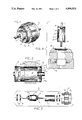
Referring to the drawings and particularly to FIG. 1, a frameless electric motor 1 is illustrated including an outer annular stator unit 2 within which a self-contained rotor unit 3 is mounted. The stator unit 2 includes an annular core 4 with a winding 5 wound on the inner peripheral face thereof in accordance with conventional practice and defining a clear axial opening or bore 6 through the stator core 4. The rotor unit 3 is a self-contained assembly, which in accordance with the teaching of the present invention, is secured within and to the stator bore 6 of core 4. Generally, the rotor unit 3 includes an outer tubular member 7 which is fixedly secured, preferably by a press fit, within the stator bore 6. The tubular member 7 projects from the opposite ends of the core 4. Rotor end plates 8 are secured, one each, within the opposite ends of the tubular member 7. The end plates 8 are shown as generally cup-shaped member having an outer flange telescoped into the end of the tubular member. The end plates 8 are secured in place, as by a spot weld 9a, a press fit or other suitable construction. A rotor, including a rotor core 10 and a suitable internal winding is mounted on a shaft 11. The shaft 11 extends from the opposite ends of core 10 through the end plates 8 and 9, with at least one end projecting from the tubular member and end plates. Each of the end plates 8 includes a similar rotary bearing unit 12 secured to the end plates, with the corresponding end of the shaft 11 journalled therein. The diameter of the rotor core 10 is slightly less than the internal diameter of the tubular member 7 and defines a constant air gap 13. The length of the air gap 13 and the thickness of member 7 is selected to define the specified air gap required for proper operation of motor 1. The rotor unit 3 is appropriately balanced for rotation within the enclosure member 7. End seal caps 14 are shown secured over the opposite ends of the tubular member 7 to seal the bearing and rotor.
The rotor unit 3 is totally enclosed within its own supportive enclosure or housing defined by the tubular member, the end plates 8 and 9 and end caps 13 to form a separate self-contained and effectively sealed module. The self-contained module is secured and supported within the stator unit by an appropriate interengagement between the external surface of the member 7 and the internal surface of the stator bore 6. In a preferred construction, the tubular member 7 is secured by an interference fit between the member 7 and stator core 2, as by a press fit. The tubular member 7 is formed of an appropriate relatively thin non-magnetic material such as stainless steel or other non-magnetic material at least in the air gap 13 between the rotor core 10 and the stator core 4. The tubular member 7 and the end plates 8 and 9 can be readily constructed of a sufficiently self-supporting metal or other material to rotatably support the rotor 10 in the final assembly. In the design of the unit, consideration must of course be given to the side loads created by the interacting magnetic forces and the like as well as the mechanical loads placed on the bearing supports by the driven load device, not shown. The tubular member 7 is formed of a minimum necessary thickness to insure the desired mechanical support and therefore minimizes the air gap 13 between the stator and rotor cores. The minimum air gap is of course significant to maximize the magnetic efficiency of the motor.
The frameless motor can then be utilized in any desired manner such as that conventionally used to date. For example, conventional cushioned end rings, flexible isolation arms, mounting studs or the like can be used with the illustrated motor. The open construction of the stator of course will normally require mounting of the motor in an enclosure to isolate the stator windings from the environment.
The two-piece motor 1 can be assembled and formed in any desired sequence of assembly in which the tubular member 7 is secured within the bore 6 of stator core 4, and preferably by an interference or press fit between of the tubular member 7 and the stator core 4. For example, the rotor unit can be formed as a complete enclosed sub-assembly separate from the stator unit 2, as shown at 15 in FIG. 4. After such assembly, the stator unit 2 is mounted in a suitable fixture 16 and the rotor module 15 is aligned with stator bore 6 in a wound stator core 4, as shown in FIG. 5, and press fitted into the bore 6. The cores 4 and 10 are precisely aligned with the air gap 13 between the two cores. The end caps 14 are then secured to the rotor module 15.
An alternative method of assembly is shown in FIG. 6 in which the tubular member 7 is press fitted directly into the bore 6 of the wound stator core 4 prior to assembly of the rotor and shaft 11. One end plate 8 is pre-assembled with the member 7, or assembled therewith immediately after press fitting. In a preferred construction, as shown in FIG. 5, the tubular member 7 and the end plate 8 are formed as a single drawn element similar to a drawn cup-shaped member such as widely formed for beverage cans and the like. The bearing support flange 16 is integrally formed with the end plate 8 and the bearing 12 assembled with the end plate. The tubular member 7 is press fitted to the bore 6 and the rotor core 10 and then assembled through the open end of the member 7, with the shaft 7 journaled in the integral end plate 8. The second end bearing plate 8 is placed over the shaft and secured into the open end of the tubular member 7.
Where a separate end plate 8 is provided, a press fit provides a simple, reliable and cost effective construction.
One practical construction of the present invention includes a thin stainless metal tube having a thickness of approximately 0.007 inches. Pressed metal end plates and standard bearings secured in opposite ends of the thin metal tube. The metal tube has an exterior diameter of 2.500 inches which was press fitted within a stator core bore. The stator bore 6 had a diameter of 2.509 inches to establish a firm interengagement and interference fit. The rotor module is of course necessarily constructed with sufficient rigidity to resist the magnetic and applied side loads appearing on the rotor and rotor shafts. Further, the metal tube has sufficient stability to maintain clearance between the outside diameter of the rotor core and the inside diameter of the metal tube, within the specified normal minimum air gap 13 between the stator and rotor cores for the motor. The thin metal tube provides a significant structural support more than adequate to support the bearing structures.
A further embodiment is shown in FIGS. 6 through 8, in which a rotor housing 18 includes a plurality of axially extended slots 19 and wedge ribs 20 to the opposite edges of the slots. The slots 19 are circumferentially spaced in accordance with the spacing of the winding slots 21 of a stator core 22. The ribs 20 are integrally secured to cylindrical end extension portions or members 23 to form the tubular housing 18. The diameter of the housing 18 between the ribs 20 is selected to establish an interference fit between the bore 24 of the stator core 25 and the outer diameter of the housing as at 26. The ribs 20 project into the stator slots 21. The ends of the tubular rotor housing 18 are closed by end bearing plates 27 such as in the prior embodiment to support a rotor core 28 with a minimum air gap 29 between the housing 18 and the rotor core. More particularly, the ribs extend radially from the housing 18 and are circumferentially spaced in accordance with the stator slots 21. The ribs project through the stator slots into abutting engagement with the winding units embedded within the slot and firmly support the winding in place. The inner location of the rib places the cylindrical plane of the housing in the plane of the stator bore. The rotor core is now spaced from the stator core by no more than the specific air gap between the stator core and the rotor core.
The housing is formed of a non-magnetic material such as metal, molded plastic, molded aluminum or the like.
If formed of metal, a thin metal plate 30, as shown in FIG. 9, may be formed and wound to form the housing. The ribs are formed by cutting the plate on a center line 31 at least for the length of the stator slots, and at the ends of the center cut for the width of the housing slots as at 32. The lips are bent outwardly to form the elongated housing slot 19 and the outwardly extended ribs 20. The slotted and ribbed plate 30 is rolled on the smooth face opposite the ribs and the abutting end edges 33 of the plate are welded or otherwise secured to form a constant internal diameter slightly greater than that of the rotor core 28.
A further embodiment of the invention is shown in FIGS. 10 and 11 wherein a self-contained motor 34 is constructed without a member within the air gap 35 between the stator core 36 and the rotor core 37.
As shown in FIG. 10, a rotor housing 38 is a ribbed cage unit including a plurality of equicircumferentially spaced ribs 39 connected to end bearing rings 40 and 41. Each rib 39 is correspondingly formed to fit within a slot opening 42 of the winding slots 43 and to project from the opposite ends of the stator core 36. Bearing plates 44 are suitably secured within the end rings 40 and 41 and are shown as cup-shaped members having a flange 45 fitted within the end ring and spot welded to the end ring as at 46. Bearings 47 are secured within the bearing plates 44 and rotatably support the rotor shaft, not shown, and thereby rotor core 37 in alignment with the stator core 36.
As most clearly shown in FIG. 11, each rib 39 is generally U-shaped with sidewalls 49 which abut the sidewalls of the slot and the winding 50 within the slot 43. The windings 50 are located within the slots 43 with each winding located on essentially the same radius with respect to the axis of rotation. The ribs 39 are located with the inside diameter of each rib referenced to the top of each slot opening 42. The ribs 39 are thus precisely located with respect to the axis of rotation and correspondingly support the bearings of the rotor unit.
The embodiment of FIGS. 10 and 11 does not introduce any member within the air gap 35 and thereby allows creating of a minimal length air gap. The ribs being secured within the slots in engagement with the winding also act as a mechanical wedge supporting the winding 50 and thereby prevents loosening of the winding and possible movement into the stator bore and destructive engagement with the rotor core 37.
The self-contained rotor unit with the housing having a nominal diameter greater than the stator bore and having the projecting rotor support provides a highly efficient ventilation and cooling of the motor when mounted in an appropriate environment. The improved cooling reduces the required magnetic material and conductive material for any given specification and thereby permits reduction in the size and cost of the core, and in the size and cost of the winding conductors. As the outer main frame normally assembled with the stator unit is eliminated, the size of the motor is somewhat smaller than other conventional motors. The elimination of the main frame and use of relative small bearing end members also reduces the material cost. The two piece construction of the stator and rotor modules with the interference or press fit to form a complete motor provides a readily fabricated and assembled motor. Structurally, the system is strong and is commercially acceptable for many applications. The separate rotor module with the interference fit also accurately locates the rotor with respect to the stator to establish an improved air gap setting. The use of the rotor end plates secured within the rotor also allows factory setting of rotor end play during assembly. Further, the end-play is controlled in the assembly process rather than in eleborate part designs as in a more conventional motor assembly.
The assembly is particularly adapted to formation of motors of different axial length. Thus, the tubular member can be formed to the length corresponding to the shaft requirements and the interrelationship between the stator and rotor. The end plates or other closure members are then appropriately secured to the ends of the proper length tube to form the total enclosure.
The present invention thus provides a simple, reliable and inexpensive motor construction particularly adapted to a frameless motor.
Various modes of carrying out the invention are contemplated as being within the scope of the following claims and particularly pointing out and distinctly claiming the subject matter which is regarded as the invention.

Claims (23)

We claim:
1. A dynamoelectric machine, comprising an annular stator having a cylindrical central bore of a constant diameter, a self-contained and enclosed rotor unit including a magnetic rotor core mounted on an intermediate portion of a supporting shaft, said rotor unit including an outer enclosure including a non-magnetic supporting tubular housing member located within said stator bore and secured to the stator bore to form the sole support of said housing member, said enclosure including end bearing plates having a first end plate secured to a first end of said tubular member and a second end plate secured to a second end of said tubular member, said rotor supported within said housing with said opposite ends of said shaft respectively rotatably mounted in said first end plate and said second end plate, said rotor unit located within said central bore of said stator core with an interference fit between the exterior surface of said housing member and said central opening to form essentially the sole support of said rotor unit and thereby defining a self-contained operative dynamoelectric machine.
2. The machine of claim 1 wherein said housing member is a tube of a constant diameter and is secured to said stator bore by an interference fit between said tube and said bore.
3. The machine of claim 1 wherein said stator includes a plurality of radially distributed winding slots in said inner bore and a winding wound in said slots, said housing member includes a plurality of radial ribs projecting into said winding slots to secure the housing member in place.
4. The machine of claim 3 wherein said ribs engage said winding in said slots and support said windings.
5. The frameless dynamoelectric machine of claim 2 wherein said tube is formed of non-magnetic steel having a thickness of essentially 0.007 inches and a diameter about 2.509 inches greater than said stator bore.
6. The machine of claim 2 wherein said housing member is stainless steel.
7. A dynamoelectric machine, comprising an annular stator having a cylindrical central bore of a constant diameter, a self-contained and enclosed rotor unit including a magnetic rotor core mounted on an intermediate portion of a supporting shaft, said rotor unit including an outer enclosure having a non-magnetic supporting tubular housing member having an internal diameter slightly greater than the outside diameter of said rotor core and an external diameter slightly greater than stator bore, said enclosure including end bearing plates having a first end plate secured to a first end of said tubular housing member and a second end plate secured to a second end of said tubular housing member, said rotor supported within said housing member with said opposite ends of said shaft respectively rotatably mounted in said first end plate and said second end plate, said rotor unit located within said central opening of said stator core with an interference fit between the exterior surface of said housing member and said control opening to form essentially the sole support of said rotor unit and thereby defining a self-contained operative dynamoelectric machine.
8. The dynamoelectric machine of claim 7 wherein said tubular housing member is formed of a non-magnetic metal having a thickness of essentially 0.007 inches.
9. The machine of claim 8 wherein said housing member is stainless steel.
10. The dynamoelectric machine of claim 7 wherein said end plates are identical elements, each of said end plates having a flange member defining a cylindrical surface having a diameter slightly greater than the internal diameter of said tubular housing member, said end plate members being secured within the ends of said tubular housing member by an interference fit.
11. the dynamoelectric machine of claim 7 wherein said bearing supports are plate-like members having an annular flange adapted to telescope over the housing member, and including an outer sealing cap telescoped over the end of said rotor.
12. The machine of claim 7 wherein said tubular housing member is a constant diameter tube.
13. The machine of claim 12 wherein said housing member is formed of a non-magnetic metal having a thickness on the order of 0.007.
14. The machine of claim 7 wherein said tube member has an outside diameter approximately 0.0005 inches greater than the internal diameter of said stator bore.
15. The machine of claim 7 wherein said end plates are formed as generally cup-shaped members having an outer annular integral sidewall of an outer diameter slightly in excess of the internal diameter of said tubular housing member, said cup-shaped member being press fitted within said tubular housing member to firmly support said end plates to said tubular housing member.
16. The machine of claim 7 wherein said tubular housing member and said one end plate are integrally formed as a single integral member.
17. The machine of claim 16 wherein the second of said end plates is secured to said tubular housing member by an interference fit.
18. A rotor structure including a rotor core for mounting within the bore of an annular stator core having a constant diameter opening with a minimum airgap between the stator core and rotor core, said core mounted on a shaft projecting coaxially from opposite ends thereof and having an outer cylindrical surface, the improvement comprising a cylindrical tube member telescoped over the core and projecting axially therefrom having a central axis end plate members secured one each to the opposite side of said rotor core to said tube member, bearings in each of said end plates located on said axis and supporting said shaft to define a self-contained rotor unit, said tube member being spaced slightly from said rotor core and adapted to be secured within said stator core with an interference fit between the exterior surface of said tube member and the interior surface of said core at least in the common axial portion between the stator core and the rotor core, and said tube member being formed of a thin high strength material to form the sole support for said bearings and said rotor core.
19. The rotor structure of claim 18 wherein said stator core includes circumferentially distributed winding stator slots, and said cylindrical tube member includes radial ribs projecting radially outwardly, said ribs being spaced in accordance with the stator slots and having a length corresponding to the axial length of the stator slots.
20. The method of forming a dynamoelectric machine including an annular stator with a constant diameter central stator opening, and a rotor having a rotor core with a shaft projecting coaxially from opposite ends of the rotor core and with an outside diameter less than the internal diameter of said stator core to define an air gap between the stator core and the rotor core with the rotor concentrically mounted within the stator core, comprising assembling a tubular housing member with end bearing plates closing the opposite end of said housing member, said end bearing plates each including a bearing member located on a common rotary axis, assembling said rotor within said housing member with said shaft journalled in said bearing members to provide a self-contained enclosed rotor module, and assembling said housing member within said stator core opening with said rotor core aligned with said stator core and with an interference fit between the external surface of the tubular housing member and the external surface of the stator core, said interference fit constituting the sole operating support of said rotor within said stator core to permit operation defining an operative dynamoelectric machine.
21. In the method of claim 20, wherein said rotor module is formed prior to assembly with said stator core unit, and said housing member is press fitted within said stator core opening after said forming of said self-contained module.
22. In the method of claim 20, wherein said housing member is press fitted within said stator core openings prior to the assembly of said rotor within said housing member.
23. In the method of claim 20, wherein said housing member is assembled with a single end plate to form a sub-assembly, and including the step of press fitting said housing into said stator core opening as said sub-assembly, thereafter assembling said rotor within said housing member and said first end plate, and thereafter assembling said second end plate with said rotor and said open end of said tubular housing member to complete forming of said dynamoelectric machine.
US07/412,855 1989-09-07 1989-09-07 Dynamoelectric machine Expired - Fee Related US4999533A (en)

Priority Applications (1)

Application Number Priority Date Filing Date Title
US07/412,855 US4999533A (en) 1989-09-07 1989-09-07 Dynamoelectric machine

Applications Claiming Priority (1)

Application Number Priority Date Filing Date Title
US07/412,855 US4999533A (en) 1989-09-07 1989-09-07 Dynamoelectric machine

Publications (1)

Publication Number Publication Date
US4999533A true US4999533A (en) 1991-03-12

Family

ID=23634771

Family Applications (1)

Application Number Title Priority Date Filing Date
US07/412,855 Expired - Fee Related US4999533A (en) 1989-09-07 1989-09-07 Dynamoelectric machine

Country Status (1)

Country Link
US (1) US4999533A (en)

Cited By (26)

* Cited by examiner, † Cited by third party
Publication number Priority date Publication date Assignee Title
US5465681A (en) * 1994-03-02 1995-11-14 Eastman Kodak Company Coating roll drive
US5486728A (en) * 1992-08-25 1996-01-23 Seiko Instruments Inc. Micromotor
US5584621A (en) * 1995-06-13 1996-12-17 Bertsche Engineering Corp. Direct drive multiple axes rotary spindle head for milling machine
US5723926A (en) * 1995-04-25 1998-03-03 Minebea Co., Ltd. Stepping motor
US5783886A (en) * 1996-08-06 1998-07-21 Samsung Electro-Mechanics Co., Ltd. Spindle motor having magnetic bearing
US6124656A (en) * 1996-04-11 2000-09-26 Interroll Holding Ag Stainless steel cap
WO2002033804A1 (en) * 2000-10-17 2002-04-25 Minebea Co., Ltd. Rotor unit for an electromotor and an internal rotor electromotor
WO2002007290A3 (en) * 2000-07-14 2002-07-18 Minebea Co Ltd Rotor assembly for an electric motor and electric motor with internal rotor
US6655003B2 (en) * 1998-10-05 2003-12-02 Mannesmann Vdo Ag Method of assembling an electric motor
US20040032177A1 (en) * 2001-08-29 2004-02-19 Hartnut Nitzsche Noise-damped holding of an electric motor
US20070236094A1 (en) * 2006-04-07 2007-10-11 General Electric Company Methods and apparatus for using an electrical machine to transport fluids through a pipeline
US7293340B1 (en) 2006-12-15 2007-11-13 Roundtop Machinery Industries Co., Ltd Direct drive spindle, machining center and methods of fabricating the same
US20080047120A1 (en) * 2006-08-24 2008-02-28 Hardinge, Inc. Rotary table with frameless motor
US20080054751A1 (en) * 2006-08-29 2008-03-06 Aisin Seiki Kabushiki Kaisha Motor
US20080197731A1 (en) * 2007-02-15 2008-08-21 Nidec Corporation Brushless motor and pump mounted with brushless motor
US20100111730A1 (en) * 2008-10-30 2010-05-06 Thomas Peterreins Low-noise rotary pump
CN102324813A (en) * 2011-08-03 2012-01-18 南京信息职业技术学院 Device for assembling multistage magnetic shoes and assembling method thereof
WO2013109915A1 (en) * 2012-01-20 2013-07-25 Fluor Technologies Corporation Rotor pole support ribs in gearless drives
GB2517410A (en) * 2013-07-16 2015-02-25 Aim Co Ltd A Stator and a Rotor for an Electric Motor
CN104167888B (en) * 2014-08-18 2016-08-17 中达电机股份有限公司 Motor stator base upset special frame
US9937307B2 (en) 2006-10-24 2018-04-10 Resmed Motor Technologies Inc. PAP device with core and vibration isolation system to support the core
US10483817B2 (en) 2013-07-16 2019-11-19 Equipmake Ltd Rotor for an electric motor including a structure for retaining rotor segments and permanent magnets on a hub thereof
CN110798010A (en) * 2018-08-03 2020-02-14 广东威灵电机制造有限公司 Stator-rotor assembly of motor and motor
GB2506970B (en) * 2012-08-24 2020-12-30 Borgwarner Inc A shield and coolant guide for an electric machine
US11456639B2 (en) 2017-05-24 2022-09-27 Equipmake Ltd Rotor for an electric motor
CN116345770A (en) * 2023-04-17 2023-06-27 中山格智美电器有限公司 Power generation heat dissipation type direct current brushless motor

Citations (6)

* Cited by examiner, † Cited by third party
Publication number Priority date Publication date Assignee Title
US3694906A (en) * 1971-10-14 1972-10-03 Gen Motors Corp Method for manufacturing a high speed squirrel cage rotor
US3955112A (en) * 1975-01-24 1976-05-04 Sell Otto W Hermetically sealed rotor
US4244099A (en) * 1979-01-11 1981-01-13 Tri-Tech, Inc. Method of making an electric rotating machine
US4404483A (en) * 1981-02-26 1983-09-13 Taco, Inc. Method of fabricating a wet-rotor circulator and circulator produced thereby
US4510679A (en) * 1983-08-17 1985-04-16 Sundstrand Corporation Method of refurbishing a high speed rotor
US4598218A (en) * 1983-08-17 1986-07-01 Sundstrand Corporation High speed rotor with removable can

Patent Citations (6)

* Cited by examiner, † Cited by third party
Publication number Priority date Publication date Assignee Title
US3694906A (en) * 1971-10-14 1972-10-03 Gen Motors Corp Method for manufacturing a high speed squirrel cage rotor
US3955112A (en) * 1975-01-24 1976-05-04 Sell Otto W Hermetically sealed rotor
US4244099A (en) * 1979-01-11 1981-01-13 Tri-Tech, Inc. Method of making an electric rotating machine
US4404483A (en) * 1981-02-26 1983-09-13 Taco, Inc. Method of fabricating a wet-rotor circulator and circulator produced thereby
US4510679A (en) * 1983-08-17 1985-04-16 Sundstrand Corporation Method of refurbishing a high speed rotor
US4598218A (en) * 1983-08-17 1986-07-01 Sundstrand Corporation High speed rotor with removable can

Cited By (43)

* Cited by examiner, † Cited by third party
Publication number Priority date Publication date Assignee Title
US5486728A (en) * 1992-08-25 1996-01-23 Seiko Instruments Inc. Micromotor
US5465681A (en) * 1994-03-02 1995-11-14 Eastman Kodak Company Coating roll drive
US5723926A (en) * 1995-04-25 1998-03-03 Minebea Co., Ltd. Stepping motor
US5584621A (en) * 1995-06-13 1996-12-17 Bertsche Engineering Corp. Direct drive multiple axes rotary spindle head for milling machine
US6124656A (en) * 1996-04-11 2000-09-26 Interroll Holding Ag Stainless steel cap
US5783886A (en) * 1996-08-06 1998-07-21 Samsung Electro-Mechanics Co., Ltd. Spindle motor having magnetic bearing
US6655003B2 (en) * 1998-10-05 2003-12-02 Mannesmann Vdo Ag Method of assembling an electric motor
US20030178903A1 (en) * 2000-07-14 2003-09-25 Harald Rapp Rotor assembly for an electric motor and electric motor with internal rotor
WO2002007290A3 (en) * 2000-07-14 2002-07-18 Minebea Co Ltd Rotor assembly for an electric motor and electric motor with internal rotor
US6919659B2 (en) * 2000-07-14 2005-07-19 Minebea Co., Ltd. Rotor assembly for an electric motor and electric motor with internal rotor
US20030222525A1 (en) * 2000-10-17 2003-12-04 Minebea Co., Ltd. Rotor unit for an electromotor and an internal rotor electromotor
US6946765B2 (en) 2000-10-17 2005-09-20 Minebea Co., Ltd. Rotor unit for an electromotor and an internal rotor electromotor
WO2002033804A1 (en) * 2000-10-17 2002-04-25 Minebea Co., Ltd. Rotor unit for an electromotor and an internal rotor electromotor
US20040032177A1 (en) * 2001-08-29 2004-02-19 Hartnut Nitzsche Noise-damped holding of an electric motor
US7709988B2 (en) 2006-04-07 2010-05-04 General Electric Company Methods and apparatus for using an electrical machine to transport fluids through a pipeline
US20070236094A1 (en) * 2006-04-07 2007-10-11 General Electric Company Methods and apparatus for using an electrical machine to transport fluids through a pipeline
US20080047120A1 (en) * 2006-08-24 2008-02-28 Hardinge, Inc. Rotary table with frameless motor
US20080054751A1 (en) * 2006-08-29 2008-03-06 Aisin Seiki Kabushiki Kaisha Motor
US8087154B2 (en) * 2006-08-29 2012-01-03 Aisin Seiki Kabushiki Kaisha Motor
US9937307B2 (en) 2006-10-24 2018-04-10 Resmed Motor Technologies Inc. PAP device with core and vibration isolation system to support the core
EP2076681B1 (en) * 2006-10-24 2018-05-09 ResMed Motor Technologies Inc. Brushless dc motor with bearings
US11786677B2 (en) 2006-10-24 2023-10-17 Resmed Motor Technologies Inc. Brushless DC motor with bearings
US11090453B2 (en) 2006-10-24 2021-08-17 Resmed Motor Technologies Inc Brushless DC motor with bearings
US7293340B1 (en) 2006-12-15 2007-11-13 Roundtop Machinery Industries Co., Ltd Direct drive spindle, machining center and methods of fabricating the same
US20080197731A1 (en) * 2007-02-15 2008-08-21 Nidec Corporation Brushless motor and pump mounted with brushless motor
US8398384B2 (en) * 2008-10-30 2013-03-19 Bühler Motor GmbH Low-noise rotary pump having a press-fit stator using split-core ribs and housing ribs
US20100111730A1 (en) * 2008-10-30 2010-05-06 Thomas Peterreins Low-noise rotary pump
CN102324813A (en) * 2011-08-03 2012-01-18 南京信息职业技术学院 Device for assembling multistage magnetic shoes and assembling method thereof
WO2013109915A1 (en) * 2012-01-20 2013-07-25 Fluor Technologies Corporation Rotor pole support ribs in gearless drives
US9246372B2 (en) 2012-01-20 2016-01-26 Fluor Technologies Corporation Rotor pole support ribs in gearless drives
US10298080B2 (en) 2012-01-20 2019-05-21 Fluor Technologies Corporation Rotor pole support ribs in gearless drives
GB2506970B (en) * 2012-08-24 2020-12-30 Borgwarner Inc A shield and coolant guide for an electric machine
JP2016525333A (en) * 2013-07-16 2016-08-22 イクイップメイク・リミテッドEquipmake Ltd Stator and rotor for electric motor
US10483817B2 (en) 2013-07-16 2019-11-19 Equipmake Ltd Rotor for an electric motor including a structure for retaining rotor segments and permanent magnets on a hub thereof
US20210021176A1 (en) * 2013-07-16 2021-01-21 Equipmake Ltd Stator for an electric motor and cooling thereof
US20160156251A1 (en) * 2013-07-16 2016-06-02 Equipmake Ltd A Stator And A Rotor For An Electric Motor
US11791694B2 (en) * 2013-07-16 2023-10-17 Equipmake Ltd Stator for an electric motor and cooling thereof
GB2517410A (en) * 2013-07-16 2015-02-25 Aim Co Ltd A Stator and a Rotor for an Electric Motor
CN104167888B (en) * 2014-08-18 2016-08-17 中达电机股份有限公司 Motor stator base upset special frame
US11456639B2 (en) 2017-05-24 2022-09-27 Equipmake Ltd Rotor for an electric motor
CN110798010A (en) * 2018-08-03 2020-02-14 广东威灵电机制造有限公司 Stator-rotor assembly of motor and motor
CN116345770A (en) * 2023-04-17 2023-06-27 中山格智美电器有限公司 Power generation heat dissipation type direct current brushless motor
CN116345770B (en) * 2023-04-17 2024-03-19 中山格智美电器有限公司 Power generation heat dissipation type direct current brushless motor

Similar Documents

Publication Publication Date Title
US4999533A (en) Dynamoelectric machine
US4603273A (en) Dynamoelectric machine with extended cleat assembly
US5818133A (en) Brushless motor with tubular bearing support
US5128571A (en) Hard disk driving motor
US4505031A (en) Method of assembling an electric motor
US4079597A (en) Drive unit for awnings and roller blinds
GB2281105B (en) Bearing assemblies for rotating shafts
KR950015917A (en) Outer rotor brushless DC motor
US5770904A (en) Electric motor
CN113726092B (en) Driving device
JP2931865B2 (en) Actuator with built-in motor
US20010013732A1 (en) Anti-vibration electric motor having outer rotor stably supported at two ends
US6969936B2 (en) Rotational position detecting sensor-equipped motor and biaxial motor
CN113644783B (en) Driving device
JPH0135581Y2 (en)
US4862026A (en) Motor unit bearing
US20230291272A1 (en) Motor shaft
EP0607429A1 (en) Induction motor of the outer rotor-type
US3486050A (en) Electric motor
KR102796592B1 (en) Exterior rotor Motor
JP3050938B2 (en) Spindle motor
CN223451784U (en) motor
JP3258161B2 (en) MOTOR STATOR ASSEMBLY AND ALL PERIPHERAL FLOW PUMP USING THE MOTOR STATOR ASSEMBLY
KR101093792B1 (en) Electric motor for submersible electric propeller with double structure
JPS6216034A (en) Hermetic electric compressor

Legal Events

Date Code Title Description
AS Assignment

Owner name: A. O. SMITH CORPORATION, WISCONSIN

Free format text: ASSIGNMENT OF ASSIGNORS INTEREST.;ASSIGNORS:KING, JAMES L.;LYKES, ROBERT E.;REEL/FRAME:005175/0661

Effective date: 19890901

FEPP Fee payment procedure

Free format text: PAYOR NUMBER ASSIGNED (ORIGINAL EVENT CODE: ASPN); ENTITY STATUS OF PATENT OWNER: LARGE ENTITY

FPAY Fee payment

Year of fee payment: 4

FPAY Fee payment

Year of fee payment: 8

REMI Maintenance fee reminder mailed
LAPS Lapse for failure to pay maintenance fees
STCH Information on status: patent discontinuation

Free format text: PATENT EXPIRED DUE TO NONPAYMENT OF MAINTENANCE FEES UNDER 37 CFR 1.362

FP Lapsed due to failure to pay maintenance fee

Effective date: 20030312