US499013A - Pumping-engine - Google Patents
Pumping-engine Download PDFInfo
- Publication number
- US499013A US499013A US499013DA US499013A US 499013 A US499013 A US 499013A US 499013D A US499013D A US 499013DA US 499013 A US499013 A US 499013A
- Authority
- US
- United States
- Prior art keywords
- valve
- condenser
- secured
- steam
- cylinder
- Prior art date
- Legal status (The legal status is an assumption and is not a legal conclusion. Google has not performed a legal analysis and makes no representation as to the accuracy of the status listed.)
- Expired - Lifetime
Links
- XLYOFNOQVPJJNP-UHFFFAOYSA-N water Substances O XLYOFNOQVPJJNP-UHFFFAOYSA-N 0.000 description 17
- 238000005086 pumping Methods 0.000 description 7
- 230000000153 supplemental effect Effects 0.000 description 6
- 238000004891 communication Methods 0.000 description 3
- 230000001105 regulatory effect Effects 0.000 description 3
- 241001125879 Gobio Species 0.000 description 2
- 238000002485 combustion reaction Methods 0.000 description 2
- 238000009833 condensation Methods 0.000 description 2
- 230000005494 condensation Effects 0.000 description 2
- 238000010276 construction Methods 0.000 description 2
- 230000001276 controlling effect Effects 0.000 description 2
- 238000001816 cooling Methods 0.000 description 2
- 238000010438 heat treatment Methods 0.000 description 2
- 238000012856 packing Methods 0.000 description 2
- 241001052209 Cylinder Species 0.000 description 1
- 241001275902 Parabramis pekinensis Species 0.000 description 1
- 239000011449 brick Substances 0.000 description 1
- 238000004140 cleaning Methods 0.000 description 1
- 238000007599 discharging Methods 0.000 description 1
- 210000005069 ears Anatomy 0.000 description 1
- 238000004880 explosion Methods 0.000 description 1
- 239000002609 medium Substances 0.000 description 1
- 238000000034 method Methods 0.000 description 1
- 229920000136 polysorbate Polymers 0.000 description 1
- 238000003825 pressing Methods 0.000 description 1
- 238000007789 sealing Methods 0.000 description 1
- 210000000707 wrist Anatomy 0.000 description 1
Images
Classifications
-
- F—MECHANICAL ENGINEERING; LIGHTING; HEATING; WEAPONS; BLASTING
- F01—MACHINES OR ENGINES IN GENERAL; ENGINE PLANTS IN GENERAL; STEAM ENGINES
- F01K—STEAM ENGINE PLANTS; STEAM ACCUMULATORS; ENGINE PLANTS NOT OTHERWISE PROVIDED FOR; ENGINES USING SPECIAL WORKING FLUIDS OR CYCLES
- F01K9/00—Plants characterised by condensers arranged or modified to co-operate with the engines
- F01K9/003—Plants characterised by condensers arranged or modified to co-operate with the engines condenser cooling circuits
-
- Y—GENERAL TAGGING OF NEW TECHNOLOGICAL DEVELOPMENTS; GENERAL TAGGING OF CROSS-SECTIONAL TECHNOLOGIES SPANNING OVER SEVERAL SECTIONS OF THE IPC; TECHNICAL SUBJECTS COVERED BY FORMER USPC CROSS-REFERENCE ART COLLECTIONS [XRACs] AND DIGESTS
- Y10—TECHNICAL SUBJECTS COVERED BY FORMER USPC
- Y10T—TECHNICAL SUBJECTS COVERED BY FORMER US CLASSIFICATION
- Y10T74/00—Machine element or mechanism
- Y10T74/18—Mechanical movements
- Y10T74/18056—Rotary to or from reciprocating or oscillating
- Y10T74/18176—Crank, pitman, lever, and slide
Definitions
- WITNESSES mi s/W01? W M /M 0 JLMd/ BY fi I l V 1 Q ATTORNEY.
- Tm ucnms PETERS cm, PHDTO-LITNQ. WASNINEYON, n. c.
- the object of my invention is to provide a device for raising or forcing water, which shall be simple in construction and operation, so that the presence of a skilled attendant will not be required to operate the same, and which Will be practically free from explosions and like derangements.
- My engine belongs to that class in which a vacuum is created in the power cylinder for the purpose of enabling the atmosphere to exert its pressure to drive the piston either up or down.
- My present invention is intended to be certain improvements upon the pumping engine shown and described in the application of one John A. Groshon,Serial No. 307,460, filed December 13, 1890, patented October 27, 1891, No. 462,218, and further consists in the various features and combinations shown and described.
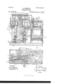
- Figure 1 is a side elevation, showing portions of the power cylinder, condenser and generator in section;
- Fig. 2 a plan view of the same, a portion of the top of the generator being broken away to disclose the interior.
- Fig. 3 is a plan and cross section, approximately through the line to, 00, Fig. 1.
- Fig. 4 is alongitudinal section taken on the line C, (3, Fig. 3, showinga portion of the condenser;
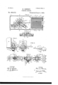
- Fig. 5 a side elevation of the valve and its easing attached to a portion of the power cylinder, partly in section;
- Fig. 6 a front elevation of the valve and its casing, power cylinder, crank and valve rod.
- Fig. 1 is a side elevation, showing portions of the power cylinder, condenser and generator in section;
- Fig. 2 a plan view of the same, a portion of the top of the generator being broken away to disclose the interior.
- Fig. 3 is a plan and cross section, approximately through the
- Fig. 7 embraces front and end views of the valve and also a side view showing the valve cap, stem and body in section;
- Fig. 8 a side view and section of the valve and casing taken on the lines F, F, Fig. 6 and E, E, Fig. 9.
- Fig. 9 shows a section of the valve and its casing, and an end elevation of the same, the section being taken on the line D, D, same figure.
- the bed preferably rectangular in form, which may be optionally provided with bolt holes 2 for securing it to a foundation.
- the bed has two tables 3 and 4. Upon the table 3 is secured the generator 5 and on the table 4 is secured the condenser 6 and attached devices.
- the fire box comprises the outer shell 7 which is interiorly provided with the ledge 8 for holding the fire brick 9 and the grate 10.
- the shell 7 is also provided with projections 11 for securing it to the table 3.
- Hand-hole plates 13' having a handle 13*, cover openings in the shell 7, which enables the interior of the shell to be got at for the purpose of cleaning it out.
- the fire box is provided with doors 12 and 13 located respectively above and below said grate.
- the shell 7 is closed at the top by means of the downwardly extending corrugated steam pot- 14, having a continuous flange 15 for securing the pot to the outer shell 7 and a boss 16 through which the steam pipe 17 leading to the power cylinder valve passes.
- the steam pot- 14 has longitudinally and upwardly extending corrugations 18. The crown of the steam pot is thus conformed for the purpose of increasing the heating surface.
- a suitable space is left be tween the outer shell 7 and steam pot 14 for the purpose of properly circulating the heat and products of combustion, the outer shell being provided with an opening 19, from which a pipe 20 for carrying off the products of combustion is led.
- the lower end or crown of the steam pot is made rectangular and the corrugations orindentations which are formed in the crown sheet of its shell extend some distance up.
- the purpose for which the steam pot is corrugated is to increase the heating surface, and to enable the heat to be transmitted farther into the interior of the shell, the heat being thereby so disposed that the Water in the center of the shell will be heated at the same time that the water nearer to the exterior of the shell is heated, this of course being determined bytheamount of theinwardextensionof the corrugations and the surface of the same.
- the top of the steam pot 14 is closed by the head 21, secured to the flange 15, an annular ring 22 being formed thereon, which holds a cover23 for rounding the top of the generator.
- a very important feature of my generator lies in doing away with the ordinary safety valve and substituting therefor a loaded or inherently heavy valve which will act as a safety valve, at the same time wholly or partly closing the upper part of the steam pot.
- My seal does not depend upon weights and levers, or springs to close the steam vent, but acts by its own weight, and as shown in Fig. 1; the seal is made by a weight 29 comparatively (in relation to the ordinary safety valve) very extensive in area.
- An annulus 30 is secured to the head 21 to provide a seat for the circumferential and beveled flange 31, they being ground steam tight in the usual manner, and the weight is provided with ribs 32 which engage With the sides of the annulus 30 to make the weight heavier at the top and enable it to bear on the sides of the annulus.
- the upper end of the weight is provided with a handle 33, by means of which the weight can be lifted to blow off or to inspect the steam pot.
- this method of sealing will be found to be amply sufficient for the purpose of closing the upper end of the steam pot, and it should be so proportioned in weight that it will not be lifted until the pressure becomes excessive.
- a feed pipe 34 leading from some suitable source of supply enters the steam pot through the head 21 and passes down to near the bottom of the same.
- This pipe is intercepted above the head 21 by an elbow 36 inelosing a two-way valve operated by a rod 41 secured at the end of the short arm of a lever 47 pivotally attached to an elbow upon the feed pipe 34, and carrying at the end of its long arm the ball-float49,the supplyof water to the steam generator being thus regulated by the height of the ball float.
- the condenser which comprises an outer shell 52 secured to the table 4 bythe flange 53, and a corrugated inner shell 54, all of which will be described farther on.
- the outer shell 52 is provided with a bracket 55 by which the upwardly extending power cylinder 56 is supported; the power cylinderbeingprovided with a like bracket 57 by which it is secured to the bracket 55 on the outer condenser shell 52.
- This outer shell 52 is also provided with bosses 58 to which the outwardly extending hangers 59 are secured, in which bearings 60 for the fly wheel shaft 61 are provided.
- Crank arms 62 are secured to the shaft 61 between the bearings 60, acrank pin 65 uniting them.
- the fly wheel 66 On one end ofthe shaft 61 is secured the fly wheel 66, and at the other end, the disk crank 67 having a crank arm 68.
- the upper portion of the outer shell 52 of the condenser is preferably smaller in diameter, as shown at 69, than the lower portion, for the purpose of adding toits strength and appearance, and to the top of the outer shell .is firmly secured upwardly extending brackets 70 upon which are formed bearings 71 for the gudgeons 72 of the beam 73.
- the outer end of the beam 73 is bifurcated at 81, and is provided with bearings for the wrist pin 82 of the connecting rod S3,the lower end 84: of the connecting rod 83 being secured to the crank pin 65 with brasses, & c., in the usual manner.
- the gudgeons 72 carry a supplemental beam 85, shorter in length than the beam 73 but working with it. To the ends of this are secured respectively the air pump rod 86 and lift pump rod 87, they both being articulated at 88, 89.
- Theliftpump cylinder 90 which is provided with the usual stuffing box 91 for packing it, is secured to the outer shell 52 of the condenser by means of flanges 92 on the pump cylinder bolted to the bosses 93, formed on the outer cylinder 52 of the condenser.
- the lower portion of the pump cylinder is flanged at 94, to which the valve seat 95 and lift valve 96 are secured, the seat having a downwardly extending section 97 upon which the elbow 98 is screwed.
- a water main 99 and vacuum chamber 100 are screwed into the elbow, the main leading from some suitable source of supply.
- the boss 93 in the outer cylinder of the condenser is channeled as at 101, Fig. 3, providingaway for the lifted water from the pump cylinder to the coudenser, and the pump rod 87 has a piston 102 of any suitable construction, the water which is forced or lifted from the pump cylinder entering the condenser.
- the bed 1 is provided with platforms 3,- 4, upon which respectively rest the generator and condenser.
- the platform 4 is provided with openings 103, 104.
- the opening 103 is located within the inner shell 54 of the condenser, and is placed in direct communication with the air pump 105, having a piston 106 and valve 107 of any preferred form, by means ofv the pipe or channel 108 extending outwardly from under the platform. This is best seen in Fig. 3.
- a discharge pipe 109 and check valve. 110 are located in the upper portion of the air pump 105, the pipe 109 leading to a bucket or other convenient place for discharging the water of "condensation.
- the valve governing the entry and exhaust of steam is secured to the lower part of the power cylinder 56, a proper port.- of entry and exhaust being provided within a casing made integral with the power cylinder, and the valve casing being secured thereto.
- the valve is of the oscillating type, and is operated by means of a connecting rod 111 secured to the crank arm 112 of the disk crank 113 at one end, and to a rockerarm 114 fast upon the valve stem 115 at the other.
- the power cylinder is cast with an outwardly extending boss 116 to which the valve casing 117 is secured by means of the ears or flanges 113 and bolts 119.
- the back part of the valve casing 117 is apertured as at 120 (best seen in Figs. 5 and 6) which aperture aligns with. a port 121 east in the boss 116, which acts alternately as a port of inlet and exhaust.
- valve casing is provided with two elbows 122,
- the elbow 122 being interiorly threaded for the reception of the steam pipe 17, which leads upwardly to the steam space of the generator, entering it at 171, Fig. 1, through the boss 16.
- the lower elbow is exteriorly threaded in order to connect the exhaust pipe 124 with it by means of the union 125.
- the valve 126 is cast in the form of a truncated cone, the valve casing being likewise interiorly conformed and ground to make a proper steam tight seat for the valve.
- the cylinder end 127 of the valve is open,the opposite end 128 being closed. This end is provided with a rib 129, which is diametrically extended across the said closed end.
- the steam port 130 and the exhaust port 131 are cut in the face of the valve, they being so distanced apart, that at every quarter turn of the disk crank 113 they will alternately open and close the inlet and exhaust ports.
- valve may be permitted to have a slight movement radial to its perpendicular axis, without pressing the valve onto its seat by nuts and bolts, as has hitherto been done; and I furthermore provide means for regulating the pressure of the valve on its seat at will without necessitating the uncapping of the valve casing or resorting to any of the usual expedients for doing this.
- I can use atmospheric pressure for the purpose of assisting a spring to keep the valve on its seat, and in some cases dispense with the spring altogether.
- valve stem 115 to which the rocker 114 and connecting rod 111 are secured is apertured as shown at 132, Figs. 7 and 8, and is interiorly screw threaded to receive the abutment screw 133, which should be fitted steam tight.
- the inner end of the valve stem is slotted transversely at 134, Fig. 7, to receive the rib 129, they being so proportioned in relation to each other, that a slight movement can be had between them.
- a spiral spring 135 is placed, its tension being regulated by the screw 133.
- the inner end of the valve stem is further provided with a disk like flange 136 which is adapted to fit upon the inner face of the casing cap 137, which is shouldered and screw threaded to close the front end of the valve casing, the flange 136 of the valve stem and inner surface of the casing cap 137 being ground together to makeaproper joint.
- the cap 137 is also provided with a nut 137' by which it can be fitted to or removed from the valve casing. It will be seen by this arrangement that I reduce the friction of the moving parts to a very small degree,doing away with the necessity of using packing as the valve can be said to pack itself, and am enabled to expeditiously assemble and disassemble them,
- the exhaust pipe 124 extends down to a stuffing box or joint 138 which is secured to a channel 139 to enable said exhaust pipe to contract or expand.
- the exhaust pipe 124 is thereby placed in connection with the channel 139, which channel leads to an aperture 140 preferably in the center of the inner cyl inder 54 of the condenser, at which point it is placed in communication with the pipe 141 which is screwed into said aperture.
- This pipe 141 extends upwardly to near the top of the inner cylinder 54 of the condenser, and is provided with holes 142 at its bottom, opening out into the inner cylinder.
- the exhaust port of the valve 126 is thereby placed in direct communication with the chamber 143 of the condenser, the pipe 141 being extended upwardly for the purpose of causing the exhaust steam or vapor to travel the entire length of the condenser and become thoroughly cooled and condensed before it passes from the condenser into the channel leading to the air pump, the holes 142 at the bottom of the pipe 141 being provided for the purpose of letting out any water which may lodge in the pipe by reason of the condensation.
- the water which is forced or displaced from the pump 90 by the action of the piston 102 passes into the outer condenser chamber 144 through the chamber 101, filling it.
- a considerable pressure is given to the water, so that the feed water which passes into the generator through the pipe 34 and ball float, enters it ata pressure equal to that of the water in the outer condenser chamber, which is intended to be much greater than the steam pressure in the generator, and it may therefore be said that the water is forced into the generator at the head or pressure of the water at the tank into which it is pumped.
- the discharge outlet for the forced or lifted water is formed by the pipe 145 secured to a boss 146 on the outer shell 69 having the air chamber 147 connected therewith.
- Another boss 148 is formed on the shell 69, opposite the boss 146 for the purpose of running the discharge pipe 145 from either side, said outlet being closed by the of a true cylinder, but is cast with sections 150 radiating from the center thereof.
- the inwardly extending portions 151, Fig. 3 extend nearly to the center of the inner condensing chamber 143, they being castintegral with the flange 152 by which the shell 54 is Secured within the shell 52 both being secured to the table 4.
- the function of these sections is not only to increase the cooling or condensing surface, but to bring it nearer to the center of the inner condensing chamber, so as to quickly and evenly condense the vapor discharged into it.
- valve as an application for that part of the present structure has been filed by me on the 12th day of January, 1892, and serially numtherein, comprising a condenser having an bered 417,7 88.
- a power cylinder open to the atmos-' phere having a movable piston, a mainbeam connected to the piston and supported in bearings, a supplemental beam operated by the main beam, an air pump connected to the supplemental beam between the bearings of the main beam and the power-cylinder, and
- a condenser on the base into which condenser one end of said channel opens, a powercylinder and apipe connecting the power-cylinder with the end of said channel remote from the condenser, a controlling-valve in said pipe a water-pump, and an air-pump, substantially as described.
- a power cylinder open to the atmosphere, a movable piston therein, and means for creating a vacuum therein, comprising a condenser having an inner and outershell, a stand pipe opening within the inner shell, a passage from the power cylinder to the stand pipe, means for projecting a condensing'mediu'm between the inner and outer shells, an air pump operative'ly connected to the power piston, a passage from the inner shell to the air pump, and means for operating the piston, substantially as described.
- a power cylinder open to the atmosphere, a movable piston therein, and means for creating a vacuum inner and outer shell, a stand pipe opening within the inner shell, a passage from the 1 power cylinder to the stand pipe, a valve in- I have shown a certain form of generator,
- a pumping engine the combination with a base provided with two channels, of a condenser, a central tube in said condenser, which tube is open at the top, a power cylinder, an air pump, which air pump is'connected with the condenser by one of the channels in the base, a tube connected with the power-cylinder and also connected by the other channel with the central tube of the conder, a tube connecting the power-cylinder with the other end of said channel, and an air pump which is connected by a channel in the base with the space bounded by the inner shell of the condenser, substantially as described.
- a condenser In a pumping engine, the combination of a condenser, shaft bearings thereon, a rock-shaft in the bearings, rocking beams secured to the shaft, a power cylinder and a fly-wheel, and power connections between them and one of the rocking beams, and a hydraulic pump and an air pump communicating with the condenser, and power connections between the-pumps and the other rocking beam, substantially as described.
- valve casing secured at the side of the cylinder, steam power cylinder and fly wheel supported on opposite sides thereof, a valve casing secured :5 to the side of the power cylinder, a rotary open-ended valve in the valve casing and means for operating the valve, substantially as described.
Landscapes
- Engineering & Computer Science (AREA)
- Chemical & Material Sciences (AREA)
- Combustion & Propulsion (AREA)
- Mechanical Engineering (AREA)
- General Engineering & Computer Science (AREA)
- Engine Equipment That Uses Special Cycles (AREA)
Description
(No Model.) 2 Sheets-Sheet 2.
H. DENNBY. PUMPING ENGINE.
No. 499,013. Patented June 6, 1893.
WITNESSES: mi s/W01? W M /M 0 JLMd/ BY fi I l V 1 Q ATTORNEY.
Tm: ucnms PETERS cm, PHDTO-LITNQ. WASNINEYON, n. c.
UNITED STATES PATENT OFFIcE.
HARMER DENNEY, OF BROOKLYN, NEW YORK.
PUMPING-ENGINE.
SPECIFICATION forming part of Letters Patent No. 499,013, dated June 6, 1893.
Application filed September 4, 1891. Serial No. 404,754. (No model.)
To all whom it may concern.-
Be it known that I, HARMER DENNEY, a citizen of the United States, residing at Brooklyn, in the county of Kings and State of New York, have made certain new and useful Improvements in Pumping-Engines, of which the following is a specification.
The object of my invention is to provide a device for raising or forcing water, which shall be simple in construction and operation, so that the presence of a skilled attendant will not be required to operate the same, and which Will be practically free from explosions and like derangements.
My engine belongs to that class in which a vacuum is created in the power cylinder for the purpose of enabling the atmosphere to exert its pressure to drive the piston either up or down.
My present invention is intended to be certain improvements upon the pumping engine shown and described in the application of one John A. Groshon,Serial No. 307,460, filed December 13, 1890, patented October 27, 1891, No. 462,218, and further consists in the various features and combinations shown and described.
In the accompanying drawings,Figure 1 is a side elevation, showing portions of the power cylinder, condenser and generator in section; Fig. 2 a plan view of the same, a portion of the top of the generator being broken away to disclose the interior. Fig. 3 is a plan and cross section, approximately through the line to, 00, Fig. 1. Fig. 4 is alongitudinal section taken on the line C, (3, Fig. 3, showinga portion of the condenser; Fig. 5 a side elevation of the valve and its easing attached to a portion of the power cylinder, partly in section; Fig. 6 a front elevation of the valve and its casing, power cylinder, crank and valve rod. Fig. 7 embraces front and end views of the valve and also a side view showing the valve cap, stem and body in section; Fig. 8 a side view and section of the valve and casing taken on the lines F, F, Fig. 6 and E, E, Fig. 9. Fig. 9 shows a section of the valve and its casing, and an end elevation of the same, the section being taken on the line D, D, same figure.
The same numerals of reference refer to like parts throughout the several views.
In the drawings 1 is the bed, preferably rectangular in form, which may be optionally provided with bolt holes 2 for securing it to a foundation. The bed has two tables 3 and 4. Upon the table 3 is secured the generator 5 and on the table 4 is secured the condenser 6 and attached devices.
The fire box comprises the outer shell 7 which is interiorly provided with the ledge 8 for holding the fire brick 9 and the grate 10.
The shell 7 is also provided with projections 11 for securing it to the table 3. Hand-hole plates 13' having a handle 13*, cover openings in the shell 7, which enables the interior of the shell to be got at for the purpose of cleaning it out. The fire box is provided with doors 12 and 13 located respectively above and below said grate. The shell 7 is closed at the top by means of the downwardly extending corrugated steam pot- 14, having a continuous flange 15 for securing the pot to the outer shell 7 and a boss 16 through which the steam pipe 17 leading to the power cylinder valve passes. The steam pot- 14 has longitudinally and upwardly extending corrugations 18. The crown of the steam pot is thus conformed for the purpose of increasing the heating surface. A suitable space is left be tween the outer shell 7 and steam pot 14 for the purpose of properly circulating the heat and products of combustion, the outer shell being provided with an opening 19, from which a pipe 20 for carrying off the products of combustion is led. The lower end or crown of the steam pot is made rectangular and the corrugations orindentations which are formed in the crown sheet of its shell extend some distance up.
The purpose for which the steam pot is corrugated is to increase the heating surface, and to enable the heat to be transmitted farther into the interior of the shell, the heat being thereby so disposed that the Water in the center of the shell will be heated at the same time that the water nearer to the exterior of the shell is heated, this of course being determined bytheamount of theinwardextensionof the corrugations and the surface of the same.
The top of the steam pot 14 is closed by the head 21, secured to the flange 15, an annular ring 22 being formed thereon, which holds a cover23 for rounding the top of the generator.
A very important feature of my generator lies in doing away with the ordinary safety valve and substituting therefor a loaded or inherently heavy valve which will act as a safety valve, at the same time wholly or partly closing the upper part of the steam pot. My seal does not depend upon weights and levers, or springs to close the steam vent, but acts by its own weight, and as shown in Fig. 1; the seal is made by a weight 29 comparatively (in relation to the ordinary safety valve) very extensive in area. An annulus 30 is secured to the head 21 to provide a seat for the circumferential and beveled flange 31, they being ground steam tight in the usual manner, and the weight is provided with ribs 32 which engage With the sides of the annulus 30 to make the weight heavier at the top and enable it to bear on the sides of the annulus. The upper end of the weight is provided with a handle 33, by means of which the weight can be lifted to blow off or to inspect the steam pot. As I propose to use steam of but one atmosphere or slightly above or below the same, this method of sealing will be found to be amply sufficient for the purpose of closing the upper end of the steam pot, and it should be so proportioned in weight that it will not be lifted until the pressure becomes excessive.
A feed pipe 34 leading from some suitable source of supply (in this case the condenser, as further set forth) enters the steam pot through the head 21 and passes down to near the bottom of the same. This pipe is intercepted above the head 21 by an elbow 36 inelosing a two-way valve operated by a rod 41 secured at the end of the short arm of a lever 47 pivotally attached to an elbow upon the feed pipe 34, and carrying at the end of its long arm the ball-float49,the supplyof water to the steam generator being thus regulated by the height of the ball float.
At a convenient distance from the generator is located the condenser, which comprises an outer shell 52 secured to the table 4 bythe flange 53, and a corrugated inner shell 54, all of which will be described farther on. The outer shell 52 is provided with a bracket 55 by which the upwardly extending power cylinder 56 is supported; the power cylinderbeingprovided with a like bracket 57 by which it is secured to the bracket 55 on the outer condenser shell 52. This outer shell 52 is also provided with bosses 58 to which the outwardly extending hangers 59 are secured, in which bearings 60 for the fly wheel shaft 61 are provided. Crank arms 62 are secured to the shaft 61 between the bearings 60, acrank pin 65 uniting them. On one end ofthe shaft 61 is secured the fly wheel 66, and at the other end, the disk crank 67 having a crank arm 68. The upper portion of the outer shell 52 of the condenser is preferably smaller in diameter, as shown at 69, than the lower portion, for the purpose of adding toits strength and appearance, and to the top of the outer shell .is firmly secured upwardly extending brackets 70 upon which are formed bearings 71 for the gudgeons 72 of the beam 73. The outer end of the beam 73 is bifurcated at 81, and is provided with bearings for the wrist pin 82 of the connecting rod S3,the lower end 84: of the connecting rod 83 being secured to the crank pin 65 with brasses, & c., in the usual manner. The gudgeons 72 carry a supplemental beam 85, shorter in length than the beam 73 but working with it. To the ends of this are secured respectively the air pump rod 86 and lift pump rod 87, they both being articulated at 88, 89. Theliftpump cylinder 90, which is provided with the usual stuffing box 91 for packing it, is secured to the outer shell 52 of the condenser by means of flanges 92 on the pump cylinder bolted to the bosses 93, formed on the outer cylinder 52 of the condenser. The lower portion of the pump cylinder is flanged at 94, to which the valve seat 95 and lift valve 96 are secured, the seat having a downwardly extending section 97 upon which the elbow 98 is screwed. A water main 99 and vacuum chamber 100 are screwed into the elbow, the main leading from some suitable source of supply. The boss 93 in the outer cylinder of the condenser is channeled as at 101, Fig. 3, providingaway for the lifted water from the pump cylinder to the coudenser, and the pump rod 87 has a piston 102 of any suitable construction, the water which is forced or lifted from the pump cylinder entering the condenser.
Referring now to the bed 1, it will be seen that it is provided with platforms 3,- 4, upon which respectively rest the generator and condenser. The platform 4 is provided with openings 103, 104. The opening 103 is located within the inner shell 54 of the condenser, and is placed in direct communication with the air pump 105, having a piston 106 and valve 107 of any preferred form, by means ofv the pipe or channel 108 extending outwardly from under the platform. This is best seen in Fig. 3. A discharge pipe 109 and check valve. 110 are located in the upper portion of the air pump 105, the pipe 109 leading to a bucket or other convenient place for discharging the water of "condensation. The valve governing the entry and exhaust of steam is secured to the lower part of the power cylinder 56, a proper port.- of entry and exhaust being provided within a casing made integral with the power cylinder, and the valve casing being secured thereto. The valve is of the oscillating type, and is operated by means of a connecting rod 111 secured to the crank arm 112 of the disk crank 113 at one end, and to a rockerarm 114 fast upon the valve stem 115 at the other. The power cylinder is cast with an outwardly extending boss 116 to which the valve casing 117 is secured by means of the ears or flanges 113 and bolts 119. The back part of the valve casing 117 is apertured as at 120 (best seen in Figs. 5 and 6) which aperture aligns with. a port 121 east in the boss 116, which acts alternately as a port of inlet and exhaust. The
Ill)
valve casing is provided with two elbows 122,
' 123, which are apertured, the elbow 122 being interiorly threaded for the reception of the steam pipe 17, which leads upwardly to the steam space of the generator, entering it at 171, Fig. 1, through the boss 16. The lower elbow is exteriorly threaded in order to connect the exhaust pipe 124 with it by means of the union 125. The valve 126 is cast in the form of a truncated cone, the valve casing being likewise interiorly conformed and ground to make a proper steam tight seat for the valve. The cylinder end 127 of the valve is open,the opposite end 128 being closed. This end is provided with a rib 129, which is diametrically extended across the said closed end. The steam port 130 and the exhaust port 131 are cut in the face of the valve, they being so distanced apart, that at every quarter turn of the disk crank 113 they will alternately open and close the inlet and exhaust ports.
In View of the low pressure used in my pumping engine, I desire to reduce the friction of the moving parts as much as possible, and to that end I have provided that the valve may be permitted to have a slight movement radial to its perpendicular axis, without pressing the valve onto its seat by nuts and bolts, as has hitherto been done; and I furthermore provide means for regulating the pressure of the valve on its seat at will without necessitating the uncapping of the valve casing or resorting to any of the usual expedients for doing this. By this flexible union of the Valve and stem,I can use atmospheric pressure for the purpose of assisting a spring to keep the valve on its seat, and in some cases dispense with the spring altogether.
The valve stem 115 to which the rocker 114 and connecting rod 111 are secured, is apertured as shown at 132, Figs. 7 and 8, and is interiorly screw threaded to receive the abutment screw 133, which should be fitted steam tight. The inner end of the valve stem is slotted transversely at 134, Fig. 7, to receive the rib 129, they being so proportioned in relation to each other, that a slight movement can be had between them. Between the abutment screw 133, and rib 129 a spiral spring 135 is placed, its tension being regulated by the screw 133. The inner end of the valve stem is further provided with a disk like flange 136 which is adapted to fit upon the inner face of the casing cap 137, which is shouldered and screw threaded to close the front end of the valve casing, the flange 136 of the valve stem and inner surface of the casing cap 137 being ground together to makeaproper joint. The cap 137 is also provided with a nut 137' by which it can be fitted to or removed from the valve casing. It will be seen by this arrangement that I reduce the friction of the moving parts to a very small degree,doing away with the necessity of using packing as the valve can be said to pack itself, and am enabled to expeditiously assemble and disassemble them,
, the arrangement permitting the atmosphere to force the valve onto its seat by reason 'of the vacuum created in the power cylinder. The exhaust pipe 124 extends down to a stuffing box or joint 138 which is secured to a channel 139 to enable said exhaust pipe to contract or expand. The exhaust pipe 124 is thereby placed in connection with the channel 139, which channel leads to an aperture 140 preferably in the center of the inner cyl inder 54 of the condenser, at which point it is placed in communication with the pipe 141 which is screwed into said aperture. This pipe 141 extends upwardly to near the top of the inner cylinder 54 of the condenser, and is provided with holes 142 at its bottom, opening out into the inner cylinder. The exhaust port of the valve 126 is thereby placed in direct communication with the chamber 143 of the condenser, the pipe 141 being extended upwardly for the purpose of causing the exhaust steam or vapor to travel the entire length of the condenser and become thoroughly cooled and condensed before it passes from the condenser into the channel leading to the air pump, the holes 142 at the bottom of the pipe 141 being provided for the purpose of letting out any water which may lodge in the pipe by reason of the condensation.
As before stated, the water which is forced or displaced from the pump 90 by the action of the piston 102, passes into the outer condenser chamber 144 through the chamber 101, filling it. During this act, a considerable pressure is given to the water, so that the feed water which passes into the generator through the pipe 34 and ball float, enters it ata pressure equal to that of the water in the outer condenser chamber, which is intended to be much greater than the steam pressure in the generator, and it may therefore be said that the water is forced into the generator at the head or pressure of the water at the tank into which it is pumped. The discharge outlet for the forced or lifted water is formed by the pipe 145 secured to a boss 146 on the outer shell 69 having the air chamber 147 connected therewith. Another boss 148 is formed on the shell 69, opposite the boss 146 for the purpose of running the discharge pipe 145 from either side, said outlet being closed by the of a true cylinder, but is cast with sections 150 radiating from the center thereof. The inwardly extending portions 151, Fig. 3, extend nearly to the center of the inner condensing chamber 143, they being castintegral with the flange 152 by which the shell 54 is Secured within the shell 52 both being secured to the table 4. The function of these sections is not only to increase the cooling or condensing surface, but to bring it nearer to the center of the inner condensing chamber, so as to quickly and evenly condense the vapor discharged into it. The vapors traversing the entire height of the pipe 141 are subjected to a greater cooling surface than would be the case if theywere discharged directly into the condensing chamber, as is the usual practice, and this feature combined with the peculiarly configured shell 54 and the Water column about its exterior, all tend to make a most efficient condensing device.
valve, as an application for that part of the present structure has been filed by me on the 12th day of January, 1892, and serially numtherein, comprising a condenser having an bered 417,7 88.
It is obvious that many changes may be made in the structure without depart-ing from my invention.
feeder, and safety valve herein, but do not intend to claim the same, their presence in this-application being simply for the purpose of showing and describing a complete and operative device.
I claim- 1. A'main beam suitably supported, a power cylinder connected to one end of the beam,
power absorbing devices at the other end, means for controlling the admission and 'X- haust of steam, a supplemental beam operf ated by the main beam, an air pump connected'to one end of the supplemental beam, and a pump for forcing or lifting waterat'the denser, and a cont-rollingvalve in the tube other, substantially as described.
2. A power cylinder open to the atmos-' phere having a movable piston, a mainbeam connected to the piston and supported in bearings, a supplemental beam operated by the main beam, an air pump connected to the supplemental beam between the bearings of the main beam and the power-cylinder, and
a water-pump connected with the other end of the supplemental-beam, substantially as described.
3. The combination with a power cylinder and power-absorbing devices, of a rocking beam having one end connected with a piston in the power-cylinder and its other end with the power-absorbing devices, with means for controlling the admission and exhaust of steam from said power-cylinder, a supplemental beam operated with the main-beam, and an air-pump connected with one end of the supplemental-beam and a water-pump connected with the other. end of the supplemental-beam, substantially as described.
4. In a pumping-engine, the combination, with a base, in which a channel is formed, of
a condenser on the base, into which condenser one end of said channel opens, a powercylinder and apipe connecting the power-cylinder with the end of said channel remote from the condenser, a controlling-valve in said pipe a water-pump, and an air-pump, substantially as described.
5. In a pumping engine, a power cylinder open to the atmosphere, a movable piston therein, and means for creating a vacuum therein, comprising a condenser having an inner and outershell, a stand pipe opening within the inner shell, a passage from the power cylinder to the stand pipe, means for projecting a condensing'mediu'm between the inner and outer shells, an air pump operative'ly connected to the power piston, a passage from the inner shell to the air pump, and means for operating the piston, substantially as described.
6. In a pumping engine, a power cylinder open to the atmosphere, a movable piston therein, and means for creating a vacuum inner and outer shell, a stand pipe opening within the inner shell, a passage from the 1 power cylinder to the stand pipe, a valve in- I have shown a certain form of generator,
tercepting said passage way, a pipe leading from the valve to a source of steam supply, means for operating the valve, and devices for projecting a conde-nsing'med-ium between the inner and outer shells substantially as described.
7. In a pumping engine, the combination with a base provided with two channels, of a condenser, a central tube in said condenser, which tube is open at the top, a power cylinder, an air pump, which air pump is'connected with the condenser by one of the channels in the base, a tube connected with the power-cylinder and also connected by the other channel with the central tube of the conder, a tube connecting the power-cylinder with the other end of said channel, and an air pump which is connected by a channel in the base with the space bounded by the inner shell of the condenser, substantially as described.
9. In a pumping engine, the combination of a condenser, shaft bearings thereon, a rock-shaft in the bearings, rocking beams secured to the shaft, a power cylinder and a fly-wheel, and power connections between them and one of the rocking beams, and a hydraulic pump and an air pump communicating with the condenser, and power connections between the-pumps and the other rocking beam, substantially as described.
10. The combination of a bed, a-steam generator, condenser, and power cylinder arranged collinearly over the bed, a valve cas- 11. The combination of a steam generator,
condenser and power cylinder, a valve casing secured at the side of the cylinder, steam power cylinder and fly wheel supported on opposite sides thereof, a valve casing secured :5 to the side of the power cylinder, a rotary open-ended valve in the valve casing and means for operating the valve, substantially as described.
Signed at the city, county, and State of 20 New York this 26th day of August, 1891.
I-IARMER DENNEY. Witnesses:
M. E. STODIDARD, JOSEPH L; LEVY.
Publications (1)
| Publication Number | Publication Date |
|---|---|
| US499013A true US499013A (en) | 1893-06-06 |
Family
ID=2567847
Family Applications (1)
| Application Number | Title | Priority Date | Filing Date |
|---|---|---|---|
| US499013D Expired - Lifetime US499013A (en) | Pumping-engine |
Country Status (1)
| Country | Link |
|---|---|
| US (1) | US499013A (en) |
-
0
- US US499013D patent/US499013A/en not_active Expired - Lifetime
Similar Documents
| Publication | Publication Date | Title |
|---|---|---|
| US1424928A (en) | Pump | |
| US2314745A (en) | Pump | |
| US36008A (en) | Improvement in hot-air engines | |
| US531182A (en) | Combustible-vapor engine | |
| US239955A (en) | Peters | |
| US1114524A (en) | Exhaust-nozzle for locomotives. | |
| US976522A (en) | Steam-storage locomotive. | |
| US1043441A (en) | Duplex steam hoisting-engine and boiler. | |
| US423898A (en) | Air-carburetor | |
| US1000489A (en) | Locomotive. | |
| US636048A (en) | Gasolene or gas engine. | |
| US663909A (en) | Steam pumping-engine. | |
| US34333A (en) | Improvement in hot-air engines | |
| US638272A (en) | Apparatus for heating and agitating air. | |
| US601218A (en) | Engine | |
| US129058A (en) | Improvement importable steam-engines and boilers | |
| US454609A (en) | George brown | |
| US1135587A (en) | Internal-combustion pumping-engine. | |
| US274753A (en) | fuller | |
| US399780A (en) | Duplex pump and condenser | |
| US1048593A (en) | Scavenging-pump construction. | |
| US236312A (en) | Portable engine | |
| US536392A (en) | Steam engine | |
| US519825A (en) | welch | |
| US573085A (en) | grubinski |