US4986696A - Method of dewatering a subterranean space, especially a mine - Google Patents
Method of dewatering a subterranean space, especially a mine Download PDFInfo
- Publication number
- US4986696A US4986696A US07/274,971 US27497188A US4986696A US 4986696 A US4986696 A US 4986696A US 27497188 A US27497188 A US 27497188A US 4986696 A US4986696 A US 4986696A
- Authority
- US
- United States
- Prior art keywords
- water
- refill
- zone
- subterranean
- pressure
- Prior art date
- Legal status (The legal status is an assumption and is not a legal conclusion. Google has not performed a legal analysis and makes no representation as to the accuracy of the status listed.)
- Expired - Fee Related
Links
- 238000000034 method Methods 0.000 title claims abstract description 34
- XLYOFNOQVPJJNP-UHFFFAOYSA-N water Substances O XLYOFNOQVPJJNP-UHFFFAOYSA-N 0.000 claims abstract description 103
- 238000005213 imbibition Methods 0.000 claims abstract description 13
- 238000005086 pumping Methods 0.000 claims abstract description 13
- 238000005422 blasting Methods 0.000 claims description 10
- 239000000463 material Substances 0.000 claims description 4
- 239000011435 rock Substances 0.000 claims description 2
- 238000012360 testing method Methods 0.000 claims description 2
- 238000010079 rubber tapping Methods 0.000 abstract description 15
- 238000005336 cracking Methods 0.000 description 15
- 239000010410 layer Substances 0.000 description 9
- 238000006073 displacement reaction Methods 0.000 description 4
- 238000002474 experimental method Methods 0.000 description 4
- 238000002347 injection Methods 0.000 description 4
- 239000007924 injection Substances 0.000 description 4
- 238000011109 contamination Methods 0.000 description 3
- 238000005259 measurement Methods 0.000 description 3
- 238000005065 mining Methods 0.000 description 3
- 238000012856 packing Methods 0.000 description 3
- 238000010306 acid treatment Methods 0.000 description 2
- 238000013459 approach Methods 0.000 description 2
- 230000004888 barrier function Effects 0.000 description 2
- 230000005484 gravity Effects 0.000 description 2
- 238000010521 absorption reaction Methods 0.000 description 1
- 230000015556 catabolic process Effects 0.000 description 1
- 239000004568 cement Substances 0.000 description 1
- 239000003638 chemical reducing agent Substances 0.000 description 1
- 230000000994 depressogenic effect Effects 0.000 description 1
- 230000003292 diminished effect Effects 0.000 description 1
- 230000000694 effects Effects 0.000 description 1
- 230000002349 favourable effect Effects 0.000 description 1
- 239000011229 interlayer Substances 0.000 description 1
- 238000012986 modification Methods 0.000 description 1
- 230000004048 modification Effects 0.000 description 1
- 230000008447 perception Effects 0.000 description 1
- 230000035699 permeability Effects 0.000 description 1
- 230000002269 spontaneous effect Effects 0.000 description 1
Images


Classifications
-
- E—FIXED CONSTRUCTIONS
- E21—EARTH OR ROCK DRILLING; MINING
- E21F—SAFETY DEVICES, TRANSPORT, FILLING-UP, RESCUE, VENTILATION, OR DRAINING IN OR OF MINES OR TUNNELS
- E21F17/00—Methods or devices for use in mines or tunnels, not covered elsewhere
Definitions
- the present invention is directed to a method of dewatering a subterranean space, especially an underground mine, which comprises collecting water artificially tapped from a water storage zone or collecting water of imbibition and transferring the water, through the use of a subterranean pumping station and at least one refill bore hole to a refill zone, said subterranean space being separated from said refill zone by an impermeable layer.
- the twofold technical task namely to remove the water from the mine-field continuously and to return the stock of water abstracted from the subterranean water storage zone, is a well known prior art method which is complicated and expensive. Also, when reinjecting the water from the surface, the risk of contamination is enhanced.
- the concept of the present invention is based on the perception that the water tapped from the subterranean water storage zone for protecting the subterranean space or the water of imbibition can be directed from the same subterranean space to a refill zone for maintaining the subterranean water balance if two conditions are met.
- the first condition is that there should be a zone of sufficiently high hydraulic resistance between the tapped subterranean space and the refilled zone of the subterranean water-system.
- the second condition is that between the mine-fields and the refill zone of the subterranean water-system there should be an impermeable seam in which the water pressure causing the spontaneous hydraulic cracking exceeds the injection pressure in use.
- the water output of tapped water or the amount of water of imbibition is strongly increased.
- the water pressed back to the subterranean water-system will cause hydraulic cracking through the impermeable seam and thus the water of the subterranean water storage system will rush into the mine while it is being refilled.
- the method comprises artificially tapping a water storage zone or collecting water of imbibition and transferring the water through a subterranean pumping station to a refill zone which is separated from said subterranean space by an impermeable seam.
- the water is transferred to the refill zone using at least one refill boring, and is achieved by flooding said refill zone directly from said subterranean space with said water without first raising the water to the surface.
- Another characteristic feature of the present invention involves flooding said refill zone by a pressure less than both the hydraulic resistance between said water storage zone and said refill zone and the lowest rock strength of said impermeable layer between said subterranean space and said refill zone.
- the present method further comprises test blasting said impermeable layer and measuring the blasting strength of the impermeable layer and transferring the water to said refill zone at a pressure of at least 5%, preferably 10 to 15% less than said blasting pressure (strength).
- the method may include reducing the refill pressure by methods, such as e.g., acid treatment and/or blasting in said refill borings.
- a packing material or cement material may be placed in at least one bore hole between said water storage zone and said refill zone so as to increase the impermeability of the impermeable layer.
- the present method may include clarifying said water of imbibition before flooding said refill zone.
- At least part of the water of imbibition or the water tapped from the water storage zone by filter wells is collected preferably in a closed or at least contamination protected gravity collector duct and conducted to a reinjecting pumping station set up in the mine.
- the water is refilled through reinjecting borings to the sector of the water storage zone that is separated from the tapped zone of the subterranean water storage system by a zone of high hydraulic resistance and separated from the mine-fields by an impermeable seam with a strength against hydraulic cracking greater than the injection pressure.
- the sufficient hydraulic resistance between the tapped and injected zones can be achieved also by the proper selection of the water storage zone. In other cases the hydraulic resistance between the tapping and refilling zones should be increased by filling the routes of water at least partly as additional measurements.
- the safety against hydraulic cracking of the impermeable seam between the mine or other subterranean space and the refill zone of the water storage should be checked by two gauges, namely the pressure gauge of the experimental blasting injection in the impermeable seam and the pressure gauge of the experimental reinjection in the water storage zone.
- the most unfavorable smallest strength against cracking should be increased suitably by determining the distance between the refill zone and the mine, at most up to the limit according to the original stress condition and/or by reducing the necessary refill pressure either by increasing the number of refill borings or by known methods, e.g. acid treatment or blastings, applied in the reinjection wells.
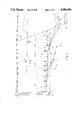
- FIG. 1 an example of the method according to the invention is shown for the hydro-geological circumstances wherein the layers to be tapped and to be refilled are in distant hydraulic contact.
- FIG. 2 relates to the case wherein both the tapping and refilling are carried out in the same water storage, however the tapping and refilling areas are hydraulically not directly connected, due to a tectonic displacement.
- FIG. 3 is directed to the case, wherein the connection between the tapping and refill zones is diminished by partially packing the water routes.
- FIG. 4 relates to the case when the purpose is to moderate the output of the water-raising in an already operating mine, e.g. for lack of capacity or to reduce delivery costs and the harmful water economic effects of tapping the subterranean water storage system in the same time.
- a further difference to the previous examples is that the water appears in the mine as a water of imbibition instead of or beside the tapping borings.
- the water storage zone 2 is tapped by the tapping borings 8 initiated from the subterranean space 1 itself for protecting the subterranean space. Tapping the initial water level 24 of the water storage zone 2 produces the depressed water level 11. During the period before refilling, the tapped water is raised to the surface by the safety pumping station 17 through the delivery pipe 18.
- the cracking pressure P r necessary for cracking up the impermeable seam 4 should be gauged in the blasting-injecting boring 9 set next to the planned reinjection in the impermeable seam 4, on one side of the refill zone 3, and then the blasting-injecting boring 9 is fully packed with an afterhardening material. Then in the experimental refill boring 10 set in the refill zone 3 started in the direction of the previous blasting experiment, an experiment for the reinjection of water is carried out by a reinjection pressure which is 85 to 90% of the cracking pressure P r at most, to determine the water amount which can be refilled by the refill pump 12 through one boring.
- the system of the tapping borings 8 and the refill borings 5 should be extended simultaneously, to achieve the desired purpose.
- the water of the 8 tapping borings, after settling, are conducted through the pipeline 13 and the refill pump 12 to the refill borings 5.
- Each of the refill borings 5 are equipped with a known pressure reducer, e.g. a blow-off valve, suitably adjusted at 90% of the P r cracking pressure.
- the unsettled part of the water from the tapping borings 8 is raised to the surface by the safety pumping station 17 through the delivery pipe 18.
- the capacity of the safety pumping station 17 is dimensioned in case of a breakdown in part of the tapping-refilling system.
- the example shown in FIG. 2 can be applied in the case the water storage zone 2 is tectonically cut, that is, there is a sufficiently high hydraulic resistance between the tectonically divided parts.
- the water storage zone 2 is in the closest cover of the subterranean space 1.
- the refill zone 3 is separated by the impermeable seam 4 from the water storage zone 2 because of a tectonic displacement 19.
- the subterranean space 1 can approach the refill zone 3 to the extent that the impermeable seam 4 provides protection against hydraulic cracking.
- the mining operation can be first extended up to the preliminary field barrier 20, a safe distance of about 100 to 150 m to the refill zone 3, then the cracking pressure P r is gauged in a set of blasting-injecting borings 9 directed to the refill zone 3. Knowing the gauged values, the distance from the subterranean space 1 to the refill zone 3 is determined so that the reinjecting pressure is 85 to 90% of the P r cracking pressure, lest it exceed the original water pressure of the refill zone 3. Thereafter the subterranean space 1 approaches the refill zone 3 up to the allowable field barrier 21 under the protection of the tapping borings 8 and the safety pumping station 17. Then a new blasting-injecting boring 9 is placed and the value of the cracking pressure is gauged in it. Depending on the gauged values the procedure should be repeated or followed according to the example shown in FIG. 1.
- the difference in the hydro-geological situation shown in FIG. 2 is that the tectonic displacement 19 did not disturb the hydraulic contact between the water storage zone 2 and the refill zone 3.
- the water routes along the tectonic displacement 19 should be at least partly packed through the packing borings 6 laid suitably from the surface, thus establishing the zone 23 of increased hydraulic resistance.
- the further procedure is as in the example of FIG. 2.
- the water 7 of imbibition appears in the subterranean space 1 from the underside water storage zone 2 through the insufficient thickness of impermeable seam 4 and is conducted by the gravity duct 25 to the safety pumping station 17.
- the cover-side refill zone 3 can be counted on, the water level before refill of which is much lower than the surface level.
- the water storage zone 2 and the refill zone 3 are hydraulically contacted by a discordance of layers just as in the geological situation in FIG. 1.
- the subterranean space 1 is separated from the refill zone 3 by the impermeable seam 4.
- the safety pumping station 17 can be partly released, and thus the energy expenses of the water being raised can be reduced by the difference between the raised water level 15 and the surface level, and the water balance can be improved by the amount of water refilled.
- the advantages of the application of the method according to the present invention are as follows:
- the water tapped from the subterranean water system is returned directly to the refill zone and thus the investment and operation expense of dewatering and refilling are reduced when compared to that of known methods.
- the costly water treatment before refilling is generally unnecessary because the water is usually treated entirely closed.
- the costs of raising the water level according to the method of the present invention are even lower than that of the method wherein the water is just raised to the surface without being returned. That means that the water-saving method according to the present invention is cheaper than the traditional water-wasting method.
Landscapes
- Engineering & Computer Science (AREA)
- Mining & Mineral Resources (AREA)
- Life Sciences & Earth Sciences (AREA)
- General Life Sciences & Earth Sciences (AREA)
- Geochemistry & Mineralogy (AREA)
- Geology (AREA)
- Consolidation Of Soil By Introduction Of Solidifying Substances Into Soil (AREA)
- Investigation Of Foundation Soil And Reinforcement Of Foundation Soil By Compacting Or Drainage (AREA)
Abstract
Description
Claims (6)
Applications Claiming Priority (1)
| Application Number | Priority Date | Filing Date | Title |
|---|---|---|---|
| HU872693A HU199936B (en) | 1987-06-15 | 1987-06-15 | Method for dewatering underground space particularly mine cave |
Publications (1)
| Publication Number | Publication Date |
|---|---|
| US4986696A true US4986696A (en) | 1991-01-22 |
Family
ID=10960676
Family Applications (1)
| Application Number | Title | Priority Date | Filing Date |
|---|---|---|---|
| US07/274,971 Expired - Fee Related US4986696A (en) | 1987-06-15 | 1988-11-22 | Method of dewatering a subterranean space, especially a mine |
Country Status (4)
| Country | Link |
|---|---|
| US (1) | US4986696A (en) |
| AU (1) | AU2446288A (en) |
| HU (1) | HU199936B (en) |
| YU (1) | YU115388A (en) |
Cited By (18)
| Publication number | Priority date | Publication date | Assignee | Title |
|---|---|---|---|---|
| US5100563A (en) * | 1991-01-28 | 1992-03-31 | Hirotsugu Suzuki | Method for introducing pure hot-spring water directly transported from a spa into a spa house bath and for maintaining the purity and freshness of the introduced water |
| US5498105A (en) * | 1991-06-20 | 1996-03-12 | Hitachi, Ltd. | Drainage water pumping station and method for operating the same |
| US5603587A (en) * | 1992-06-18 | 1997-02-18 | Hitachi, Ltd. | Drainage water pumping station and method for operating the same |
| US6840710B2 (en) | 2001-05-15 | 2005-01-11 | Rar Group, Llc | Underground alluvial water storage reservoir and method |
| US20050186030A1 (en) * | 2004-02-24 | 2005-08-25 | Ps Systems Inc. | Direct recharge injection of underground water reservoirs |
| US20080072968A1 (en) * | 2006-09-26 | 2008-03-27 | Ps Systems Inc. | Maintaining dynamic water storage in underground porosity reservoirs |
| US20080073087A1 (en) * | 2006-09-26 | 2008-03-27 | Ps Systems Inc. | Ventilation of underground porosity storage reservoirs |
| US20080226395A1 (en) * | 2007-03-14 | 2008-09-18 | Ps Systems Inc. | Bank-Sided Porosity Storage Reservoirs |
| US20090173142A1 (en) * | 2007-07-24 | 2009-07-09 | Ps Systems Inc. | Controlling gas pressure in porosity storage reservoirs |
| WO2011148285A3 (en) * | 2010-05-26 | 2012-01-12 | Schlumberger Canada Limited | Mine dewatering system and method |
| CN103953391A (en) * | 2014-04-29 | 2014-07-30 | 中国矿业大学(北京) | Mine high-temperature burst water treatment method |
| US20140321914A1 (en) * | 2013-04-30 | 2014-10-30 | Halliburton Energy Services, Inc. | Controlled Dewatering of Confined, Saturated Formations in Excavation Mines |
| US20150125209A1 (en) * | 2012-04-28 | 2015-05-07 | China Shenhua Energy Company Limited | Method for Distributed Storage and Use of Underground Water in Mine |
| CN104696010A (en) * | 2015-03-20 | 2015-06-10 | 青岛理工大学 | Comprehensive treatment method for mine water inrush |
| CN106205340A (en) * | 2016-09-29 | 2016-12-07 | 西安科技大学 | Mine earth's surface raceway groove flowing water is burst water yield experiment porch |
| CN115450693A (en) * | 2022-08-17 | 2022-12-09 | 中煤科工西安研究院(集团)有限公司 | Large-depth-reduction drainage method and system for steeply-inclined aquifer |
| CN116537790A (en) * | 2023-06-01 | 2023-08-04 | 中国恩菲工程技术有限公司 | Open pit filling method |
| US12146410B1 (en) * | 2023-08-07 | 2024-11-19 | Ping An Coal Mining Engineering Technology Research Institute Co., Ltd | Method for dewatering coal mine goaf by crossing neighboring goaf |
Citations (6)
| Publication number | Priority date | Publication date | Assignee | Title |
|---|---|---|---|---|
| US2126575A (en) * | 1934-07-23 | 1938-08-09 | Ranney Leo | Method of and apparatus for recovering water from and supplying water to subterranean formations |
| US2787125A (en) * | 1952-11-13 | 1957-04-02 | Phillips Petroleum Co | Underground storage system |
| US3026096A (en) * | 1960-04-12 | 1962-03-20 | Fmc Corp | Methods for controlling underground water |
| US3469405A (en) * | 1968-08-14 | 1969-09-30 | Layne New York Co Inc | Mine water barrier |
| US3705851A (en) * | 1971-11-15 | 1972-12-12 | Robert C Brauer | Waste disposal system |
| US4153297A (en) * | 1977-06-29 | 1979-05-08 | Occidental Oil Shale, Inc. | Ground water control for an in situ oil shale retort |
-
1987
- 1987-06-15 HU HU872693A patent/HU199936B/en not_active IP Right Cessation
-
1988
- 1988-06-14 YU YU01153/88A patent/YU115388A/en unknown
- 1988-10-28 AU AU24462/88A patent/AU2446288A/en not_active Abandoned
- 1988-11-22 US US07/274,971 patent/US4986696A/en not_active Expired - Fee Related
Patent Citations (6)
| Publication number | Priority date | Publication date | Assignee | Title |
|---|---|---|---|---|
| US2126575A (en) * | 1934-07-23 | 1938-08-09 | Ranney Leo | Method of and apparatus for recovering water from and supplying water to subterranean formations |
| US2787125A (en) * | 1952-11-13 | 1957-04-02 | Phillips Petroleum Co | Underground storage system |
| US3026096A (en) * | 1960-04-12 | 1962-03-20 | Fmc Corp | Methods for controlling underground water |
| US3469405A (en) * | 1968-08-14 | 1969-09-30 | Layne New York Co Inc | Mine water barrier |
| US3705851A (en) * | 1971-11-15 | 1972-12-12 | Robert C Brauer | Waste disposal system |
| US4153297A (en) * | 1977-06-29 | 1979-05-08 | Occidental Oil Shale, Inc. | Ground water control for an in situ oil shale retort |
Cited By (29)
| Publication number | Priority date | Publication date | Assignee | Title |
|---|---|---|---|---|
| US5100563A (en) * | 1991-01-28 | 1992-03-31 | Hirotsugu Suzuki | Method for introducing pure hot-spring water directly transported from a spa into a spa house bath and for maintaining the purity and freshness of the introduced water |
| US5498105A (en) * | 1991-06-20 | 1996-03-12 | Hitachi, Ltd. | Drainage water pumping station and method for operating the same |
| US6132136A (en) * | 1991-06-20 | 2000-10-17 | Hitachi, Ltd. | Drainage water pumping station and method for operating the same |
| US5603587A (en) * | 1992-06-18 | 1997-02-18 | Hitachi, Ltd. | Drainage water pumping station and method for operating the same |
| US6840710B2 (en) | 2001-05-15 | 2005-01-11 | Rar Group, Llc | Underground alluvial water storage reservoir and method |
| US20110229267A1 (en) * | 2004-02-24 | 2011-09-22 | Ps Systems Inc. | Direct recharge injection of underground water reservoirs |
| US20050186030A1 (en) * | 2004-02-24 | 2005-08-25 | Ps Systems Inc. | Direct recharge injection of underground water reservoirs |
| US7192218B2 (en) | 2004-02-24 | 2007-03-20 | Ps Systems Inc. | Direct recharge injection of underground water reservoirs |
| US20070154262A1 (en) * | 2004-02-24 | 2007-07-05 | Ps Systems Inc. | Direct Recharge Injection of Underground Water Reservoirs |
| US8074670B2 (en) | 2006-09-26 | 2011-12-13 | PS Systems, Inc. | Maintaining dynamic water storage in underground porosity reservoirs |
| US20080073087A1 (en) * | 2006-09-26 | 2008-03-27 | Ps Systems Inc. | Ventilation of underground porosity storage reservoirs |
| US20080072968A1 (en) * | 2006-09-26 | 2008-03-27 | Ps Systems Inc. | Maintaining dynamic water storage in underground porosity reservoirs |
| US20080226395A1 (en) * | 2007-03-14 | 2008-09-18 | Ps Systems Inc. | Bank-Sided Porosity Storage Reservoirs |
| US7972080B2 (en) | 2007-03-14 | 2011-07-05 | PS Systems, Inc. | Bank-sided porosity storage reservoirs |
| US20090173142A1 (en) * | 2007-07-24 | 2009-07-09 | Ps Systems Inc. | Controlling gas pressure in porosity storage reservoirs |
| AU2011259819B2 (en) * | 2010-05-26 | 2015-03-26 | Wsp Global Inc. | Mine dewatering system and method |
| WO2011148285A3 (en) * | 2010-05-26 | 2012-01-12 | Schlumberger Canada Limited | Mine dewatering system and method |
| US9822641B2 (en) | 2010-05-26 | 2017-11-21 | Wsp Global, Inc. | Mine dewatering system and method |
| US9371185B2 (en) * | 2012-04-28 | 2016-06-21 | China Shenhua Energy Company Limited | Method for distributed storage and use of underground water in mine |
| US20150125209A1 (en) * | 2012-04-28 | 2015-05-07 | China Shenhua Energy Company Limited | Method for Distributed Storage and Use of Underground Water in Mine |
| US9109338B2 (en) * | 2013-04-30 | 2015-08-18 | Halliburton Energy Services, Inc. | Controlled dewatering of confined, saturated formations in excavation mines |
| US20140321914A1 (en) * | 2013-04-30 | 2014-10-30 | Halliburton Energy Services, Inc. | Controlled Dewatering of Confined, Saturated Formations in Excavation Mines |
| CN103953391A (en) * | 2014-04-29 | 2014-07-30 | 中国矿业大学(北京) | Mine high-temperature burst water treatment method |
| CN104696010A (en) * | 2015-03-20 | 2015-06-10 | 青岛理工大学 | Comprehensive treatment method for mine water inrush |
| CN106205340A (en) * | 2016-09-29 | 2016-12-07 | 西安科技大学 | Mine earth's surface raceway groove flowing water is burst water yield experiment porch |
| CN115450693A (en) * | 2022-08-17 | 2022-12-09 | 中煤科工西安研究院(集团)有限公司 | Large-depth-reduction drainage method and system for steeply-inclined aquifer |
| CN115450693B (en) * | 2022-08-17 | 2023-07-14 | 中煤科工西安研究院(集团)有限公司 | A large-drawdown dredging method and dredging system for steeply inclined aquifers |
| CN116537790A (en) * | 2023-06-01 | 2023-08-04 | 中国恩菲工程技术有限公司 | Open pit filling method |
| US12146410B1 (en) * | 2023-08-07 | 2024-11-19 | Ping An Coal Mining Engineering Technology Research Institute Co., Ltd | Method for dewatering coal mine goaf by crossing neighboring goaf |
Also Published As
| Publication number | Publication date |
|---|---|
| YU115388A (en) | 1991-02-28 |
| HU199936B (en) | 1990-03-28 |
| HUT47167A (en) | 1989-01-30 |
| AU2446288A (en) | 1990-05-03 |
Similar Documents
| Publication | Publication Date | Title |
|---|---|---|
| US4986696A (en) | Method of dewatering a subterranean space, especially a mine | |
| US3002454A (en) | Method of fracturing earth formations | |
| CN104569352B (en) | The determination method of ash packwall, top difficult to understand structure discrimination index | |
| WO2018201706A1 (en) | Method for efficient gas drainage in coal roadway strips and regional outburst elimination through staged fracturing with long borehole floor beddings | |
| CN106869966B (en) | A kind of method for blocking of absciss layer water supply source | |
| CN111042831A (en) | Grouting reinforcement transformation method for coal seam floor limestone confined aquifer | |
| CN107816365B (en) | Coal seam drilling, blasting and pumping integrated outburst prevention method | |
| CN109611146B (en) | Separation layer water drainage grouting method | |
| CN114687796B (en) | A system for comprehensive treatment of old roof water | |
| CN110067597A (en) | A kind of mine angle of depression negative pressure visits the method for putting old dead zone ponding | |
| CN114483188B (en) | Method for treating high-mineralization mine water by reinjection of depleted oil layer | |
| CN112610249B (en) | Method for preventing and controlling water damage of mine floor under high-pressure-bearing flowing water condition | |
| SU1535992A1 (en) | Method of oriented rupture of rock | |
| CN114790915B (en) | Method, device, terminal and storage medium for pumping overburden water from ground layer to prevent water inrush | |
| CN115726756A (en) | Coal mine gas control and regional outburst elimination methods | |
| RU2136890C1 (en) | Method for degassing of coal seams | |
| JPH0213696A (en) | Under-pit hydraulic mining method of mineral resource | |
| CN113494312A (en) | Facility for eliminating water accumulation threat of adjacent goaf of working face and implementation scheme | |
| CN115898513B (en) | Outburst elimination method for coal uncovering ground drilling area of strong outburst coal seam roadway | |
| JPH0617555A (en) | Underground tank for compressed gas storage | |
| Lo et al. | Design of buried structures in squeezing rock in Toronto, Canada | |
| CN115012946B (en) | Construction method for preventing and treating well wall breakage through graded excavation and filling and waterproof structure | |
| RU2034991C1 (en) | Method of suppressing dynamic effects at developing coal seams | |
| Kaskiw et al. | Backfilling at IMC Canada K-2 potash mine | |
| CN114482914B (en) | Plugging device for oil-water well and use method |
Legal Events
| Date | Code | Title | Description |
|---|---|---|---|
| AS | Assignment |
Owner name: VESZPREMI SZENBANYAK; KOZPONTI BANYASZATI FEJLESZT Free format text: ASSIGNMENT OF ASSIGNORS INTEREST.;ASSIGNORS:PERA, FERENC;SZENTAI, GYORGY;KESSERU, ZSOLT;AND OTHERS;REEL/FRAME:004980/0976 Effective date: 19881101 Owner name: ORSZAGOS FOLDTANI KUTATO ES FURO VALLAT, VARPALOTA Free format text: ASSIGNMENT OF ASSIGNORS INTEREST.;ASSIGNORS:PERA, FERENC;SZENTAI, GYORGY;KESSERU, ZSOLT;AND OTHERS;REEL/FRAME:004980/0976 Effective date: 19881101 Owner name: VESZPREMI SZENBANYAK, HUNGARY Free format text: ASSIGNMENT OF ASSIGNORS INTEREST;ASSIGNORS:PERA, FERENC;SZENTAI, GYORGY;KESSERU, ZSOLT;AND OTHERS;REEL/FRAME:004980/0976 Effective date: 19881101 Owner name: ORSZAGOS FOLDTANI KUTATO ES FURO VALLAT, HUNGARY Free format text: ASSIGNMENT OF ASSIGNORS INTEREST;ASSIGNORS:PERA, FERENC;SZENTAI, GYORGY;KESSERU, ZSOLT;AND OTHERS;REEL/FRAME:004980/0976 Effective date: 19881101 Owner name: KOZPONTI BANYASZATIFEJLESZTESI INTEZET, HUNGARY Free format text: ASSIGNMENT OF ASSIGNORS INTEREST;ASSIGNORS:PERA, FERENC;SZENTAI, GYORGY;KESSERU, ZSOLT;AND OTHERS;REEL/FRAME:004980/0976 Effective date: 19881101 |
|
| FEPP | Fee payment procedure |
Free format text: PAYOR NUMBER ASSIGNED (ORIGINAL EVENT CODE: ASPN); ENTITY STATUS OF PATENT OWNER: LARGE ENTITY |
|
| REMI | Maintenance fee reminder mailed | ||
| LAPS | Lapse for failure to pay maintenance fees | ||
| FP | Lapsed due to failure to pay maintenance fee |
Effective date: 19950125 |
|
| STCH | Information on status: patent discontinuation |
Free format text: PATENT EXPIRED DUE TO NONPAYMENT OF MAINTENANCE FEES UNDER 37 CFR 1.362 |