US4977819A - Machine for brewing hot beverages - Google Patents
Machine for brewing hot beverages Download PDFInfo
- Publication number
- US4977819A US4977819A US07/187,374 US18737488A US4977819A US 4977819 A US4977819 A US 4977819A US 18737488 A US18737488 A US 18737488A US 4977819 A US4977819 A US 4977819A
- Authority
- US
- United States
- Prior art keywords
- machine
- heating unit
- distancing element
- housing
- units
- Prior art date
- Legal status (The legal status is an assumption and is not a legal conclusion. Google has not performed a legal analysis and makes no representation as to the accuracy of the status listed.)
- Expired - Fee Related
Links
- 235000012171 hot beverage Nutrition 0.000 title claims abstract description 16
- 238000010792 warming Methods 0.000 claims abstract description 12
- 238000010438 heat treatment Methods 0.000 claims description 59
- 239000007788 liquid Substances 0.000 claims description 27
- 238000012546 transfer Methods 0.000 claims description 9
- 238000003860 storage Methods 0.000 claims description 4
- 239000007769 metal material Substances 0.000 claims description 3
- 241001122767 Theaceae Species 0.000 abstract description 13
- 235000016213 coffee Nutrition 0.000 abstract description 12
- 235000013353 coffee beverage Nutrition 0.000 abstract description 12
- 235000013361 beverage Nutrition 0.000 abstract description 11
- 239000000463 material Substances 0.000 abstract description 6
- XLYOFNOQVPJJNP-UHFFFAOYSA-N water Substances O XLYOFNOQVPJJNP-UHFFFAOYSA-N 0.000 abstract description 5
- 240000007154 Coffea arabica Species 0.000 description 11
- 239000011521 glass Substances 0.000 description 6
- 244000299461 Theobroma cacao Species 0.000 description 5
- 238000005485 electric heating Methods 0.000 description 5
- 239000004020 conductor Substances 0.000 description 4
- 239000008267 milk Substances 0.000 description 4
- 210000004080 milk Anatomy 0.000 description 4
- 235000013336 milk Nutrition 0.000 description 4
- 241000533293 Sesbania emerus Species 0.000 description 3
- 235000009470 Theobroma cacao Nutrition 0.000 description 3
- 239000011810 insulating material Substances 0.000 description 3
- 238000005452 bending Methods 0.000 description 2
- 235000019219 chocolate Nutrition 0.000 description 2
- 238000013461 design Methods 0.000 description 2
- 239000000796 flavoring agent Substances 0.000 description 2
- 235000013355 food flavoring agent Nutrition 0.000 description 2
- 210000002445 nipple Anatomy 0.000 description 2
- 230000000284 resting effect Effects 0.000 description 2
- 238000007789 sealing Methods 0.000 description 2
- 235000013616 tea Nutrition 0.000 description 2
- 230000006978 adaptation Effects 0.000 description 1
- 239000002131 composite material Substances 0.000 description 1
- 238000010276 construction Methods 0.000 description 1
- 230000007423 decrease Effects 0.000 description 1
- 238000009826 distribution Methods 0.000 description 1
- 238000000605 extraction Methods 0.000 description 1
- 238000003780 insertion Methods 0.000 description 1
- 230000037431 insertion Effects 0.000 description 1
- 238000004519 manufacturing process Methods 0.000 description 1
- 238000000034 method Methods 0.000 description 1
- 238000013021 overheating Methods 0.000 description 1
- 229910052573 porcelain Inorganic materials 0.000 description 1
- 230000001105 regulatory effect Effects 0.000 description 1
- 230000000630 rising effect Effects 0.000 description 1
Images

Classifications
-
- A—HUMAN NECESSITIES
- A47—FURNITURE; DOMESTIC ARTICLES OR APPLIANCES; COFFEE MILLS; SPICE MILLS; SUCTION CLEANERS IN GENERAL
- A47J—KITCHEN EQUIPMENT; COFFEE MILLS; SPICE MILLS; APPARATUS FOR MAKING BEVERAGES
- A47J31/00—Apparatus for making beverages
- A47J31/04—Coffee-making apparatus with rising pipes
- A47J31/057—Coffee-making apparatus with rising pipes with water container separated from beverage container, the hot water passing the filter only once i.e. classical type of drip coffee makers
- A47J31/0573—Coffee-making apparatus with rising pipes with water container separated from beverage container, the hot water passing the filter only once i.e. classical type of drip coffee makers with flow through heaters
Definitions
- the machine of the present invention is similar to the machines disclosed in the commonly owned copending patent applications Ser. Nos.: 184,682 and 184,683 filed by Henn et al. on Apr. 22, 1988 and Apr. 22, 1988, respectively.
- the invention relates to improvements in machines for brewing coffee, tea, cocoa, chocolate and other hot beverages. More particularly, the invention relates to improvements in machines of the type wherein the outlet for a freshly brewed beverage is disposed at a level above a support for a vessel which is to collect the dispensed beverage and the support is adjacent a heating unit, particularly an electric heater for water, milk or another liquid which is to be heated and thereupon contacted with comminuted coffee beans, comminuted tea leaves or another flavoring agent serving to influence the color, taste and/or aroma of the liquid.
- a heating unit particularly an electric heater for water, milk or another liquid which is to be heated and thereupon contacted with comminuted coffee beans, comminuted tea leaves or another flavoring agent serving to influence the color, taste and/or aroma of the liquid.
- a container for a supply of liquid such as water or milk
- a heating unit which serves to raise the temperature of the liquid
- a filter holder which serves to convey heated liquid from the heating unit to the filter holder wherein the liquid is contacted by comminuted coffee beans or tea leaves
- a warming plate or another suitable support for a vessel which is to receive the freshly brewed beverage from the filter holder.
- the support is heated by the heating unit so that the temperature of the beverage which is collected by the vessel resting on the support is maintained within a desired range.
- the vessel can constitute a coffee pot, a tea pot, a thermos (vacuum) bottle or any other suitable receptacle for a freshly brewed beverage.
- a coffee or tea pot can be made of glass or porcelain, in contrast to a thermos which can comprise a bottle of glass or the like within a jacket of heat insulating material. Certain of these materials can stand elevated temperatures; therefore, the respective vessels can be placed directly onto a support which is in contact with an electric heater so that its temperature can reach a value at which a vessel made of other material would undergo permanent damage. For example, many types of glass can stand elevated temperatures and can divide the temperature uniformly or nearly uniformly all around the confined supply of a freshly brewed beverage.
- Such vessels are provided with handles of heat insulating material so that the operator of the machine can avoid direct contact with the glass wall of the vessel. Moreover, rapid distribution of heat which was transferred to such vessel by the intensively heated support of the coffee or tea making machine ensures that the temperature of the bottom part of the vessel rapidly decreases so that the bottom part can be placed onto a table, a counter or a like piece of furniture which is made of a heat-sensitive material without causing damage thereto.
- the bottom part is made of a metallic material.
- the placing of such vessel directly onto an intensively heated warming plate or a like support results in excessive heating of the bottom part of the vessel so that the thus heated bottom part is highly likely or practically certain to destroy, damage or at least deface a table, a counter or another piece of furniture serving as a rest for the vessel.
- Attempts to overcome such problems include the establishment of direct or indirect heat transmitting connections between the heating unit and the support for vessels.
- the support is placed at a greater distance from the heating unit.
- Such undertaking reduces the likelihood of overheating certain types of vessels; however, the solution is rather primitive, impractical and expensive.
- An object of the invention is to provide a novel and improved machine for brewing hot beverages which is constructed and assembled in such a way that the support for beverage-receiving vessels can be properly heated in a simple, reliable and inexpensive way.
- Another object of the invention is to provide novel and improved means for changing the rate of heat transfer between the heating unit of a coffee making or like machine and the support for pots, carafes, cups, vacuum bottles and other types of vessels for freshly brewed beverages.
- a further object of the invention is to provide a novel and improved method of converting a conventional machine for brewing hot beverages into a machine which exhibits the above outlined advantages.
- An additional object of the invention is to provide novel and improved means for transmitting heat between an electric heating unit and a warming plate in a machine for brewing coffee, tea, cocoa or other hot beverages.
- Still another object of the invention is to provide an electric heating unit which can be used in the above outlined machine.
- Another object of the invention is to provide a machine which can be rapidly converted for intensive or less intensive transfer of heat between the heating unit and the support for vessels which gather freshly brewed coffee, tea or another hot beverage.
- the invention is embodied in a machine for brewing hot beverages, such as coffee, cocoa, chocolate, tea and the like.
- the improved machine comprises a housing, a container for storage of a supply of liquid (e.g., water or milk) in the housing, an electric heating unit for liquid in the housing, a supporting unit (e.g., a warming plate) for cups, pots, carafes, vacuum bottles or other suitable beverage-receiving vessels adjacent the heating unit, and a distancing element which is interposed between the heating and supporting units and serves to reduce the transfer of heat from the heating unit to the supporting unit.
- the supporting unit can be disposed at a level above the heating unit, and the distancing element can constitute a single piece of metallic wire.
- the machine preferably further comprises means for properly locating the distancing element with reference to the housing and/or with reference to at least one of the units.
- Such locating means can comprise a male locating member and a female locating member.
- One of the locating members is provided on the distancing element and the other of the locating members can be provided on or in the housing and/or on or in the one unit.
- the distancing element can comprise a substantially annular first portion and a substantially straight second portion, and the one locating member can be provided on the second portion of such distancing element, particularly on or at that end of the second portion which is remote from the first portion.
- the second portion can extend substantially radially of and can be disposed within the annular first portion, and the one locating member can be disposed substantially centrally of the annular first portion of the distancing element.
- the first and second portions of the distancing element can be disposed in a common first plane, and the one locating member can be disposed in a second plate extending substantially at right angles to the first plane.
- the female locating member can include a socket for the male locating member.
- the socket can be provided in the heating unit and can be bounded by a substantially circular surface.
- the male locating member can be provided with several surfaces each of which is adjacent or actually abuts the circular surface of the heating unit.
- the distancing element can be removably installed between the heating and supporting units.
- the arrangement may be such that the supporting unit is installed in the housing at a predetermined level and the heating unit is disposed beneath the supporting unit and is adjustable relative thereto, namely the heating unit is movable nearer to or further away from the supporting unit depending upon whether or not the distancing element is necessary.
- the distancing element will be installed between the heating and supporting units if the supporting unit is to serve as a rest for a vessel which is incapable of standing elevated temperatures or is not supposed to be heated to an elevated temperature for another reason.
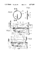
- FIG. 1 is a schematic elevational view of a machine which embodies one form of the invention, with a portion of the housing and heating unit broken away, with the distancing element removed and with a pot indicated by phantom lines;
- FIG. 2 is a plan view of the heating unit in the machine of FIG. 1;
- FIG. 3 is a plan view of a distancing element for use in the machine of FIG. 1;
- FIG. 4 is a sectional view of the distancing element as seen in the direction of arrows from the line IV--IV of FIG. 3;
- FIG. 5 is an enlarged view of a detail in the machine of FIG. 1 with the distancing element removed so that the heating unit is immediately adjacent the supporting unit which supports the pot of FIG. 1;
- FIG. 6 shows the structure of FIG. 5 but with the distancing element installed between the heating and supporting units and with a vacuum bottle on the supporting unit.
- the machine 10 of FIG. 1 is designed to make coffee, tea or another hot beverage and includes an at least partially hollow housing including a base plate 11 and a hollow bottom portion 12 on top of the base plate.
- the bottom portion 12 confines an electric heating unit 18.
- An upright portion of the housing of the machine 10 constitutes or receives a relatively large container 13 for a supply of liquid (such as water or milk) to be heated by the unit 18.
- the top portion 14 of the housing carries a detachable or pivotably or slidably mounted cover or lid 15 which can be moved from the sealing position of FIG. 1 to afford access to the opening at the top of the container 13 so that the container can be refilled at required intervals.
- the drawing shows only those parts of the improved machine 10 which are necessary for full understanding of the invention.
- the drawing does not show the electric circuit for the heating unit 18, the means for connecting such circuit with an outside source of electrical energy, the various knobs, levers, switches and other controls which can be manipulated to regulate the temperature of heated liquid, and a conduit which conveys heated liquid from the heating unit 18 upwardly and into the interior of a filter holder 16 at a level above a supporting unit 34 in the form of a warming plate mounted in the bottom portion 12 of the housing above the heating unit 18.
- Those parts which are not shown in the drawing are, or can be, identical with corresponding parts of conventional machines for brewing hot beverages, for example, of coffee making machines distributed by the assignee of the present application.
- the details of means for conveying heated liquid from the heating unit to the filter holder are disclosed in the aforementioned commonly owned copending patent applications Ser. Nos. 184,682 and 184,683 and of Henn et al.
- the base plate 11 can be placed onto a table, onto a counter or onto any other piece of furniture which is sufficiently close to an outlet so that the plug at the free end of the cord (not shown) of the machine 10 can be inserted into the outlet.
- the relatively large hollow bottom portion 12 of the housing of the machine 10 further confines the aforementioned controls and the electric circuit.
- the top portion 14 is parallel or nearly parallel to the base plate 11 and supports the filter holder 16 which can receive a hollow conical or otherwise configurated filter paper containing a supply of comminuted coffee beans, comminuted tea leaves or any other suitable flavoring agent which is to be used for the brewing of a hot beverage.
- the bottom part of the filter holder 16 carries a gate 25 which is pivotally secured thereto, as at 26, and can be moved between the illustrated sealing position and an opening position so as to permit escape of a freshly brewed beverage from the chamber of the filter holder into a pot 17 or a similar vessel (indicated in FIG. 1 by phantom lines) resting on the supporting unit 34.
- the manner in which the pot 17 can cause the gate 25 to move to open position when the pot is properly placed onto the supporting unit 34 is disclosed in the aforementioned copending patent applications Ser. Nos. 184,682 and 184,683 of Henn et al.
- the upper portion of the filter holder 16 has an intake (such as a horizontal pipe) which is connected to the upper end of the aforementioned conduit (riser) or to a manifold which contains a valving element serving to return the liquid into the container 13 if the temperature of liquid rising in the conduit does not suffice for the brewing of a satisfactory beverage. If the temperature of heated liquid in the conduit is sufficiently high, the valving element undergoes deformation to assume a position in which the conduit is sealed from the container 13 but is free to discharge heated liquid into the filter holder 16.
- the pivot 26 for the gate 25 is mounted on a cylindrical skirt-like wall of the filter holder 16 closely above the top portion of the pot 17 on the supporting unit 34.
- the gate 25 can comprise a lever which is turnable (at 26) about a horizontal pivot axis and carries a spring-biased valving element which normally seals an outlet opening in the bottom wall of the filter holder 16.
- the lever moves the valving element away from the outlet opening when pivoted in a clockwise direction, either by hand or automatically by the top part of the pot 17 when the latter is properly placed onto the supporting unit 34 above the heating unit 18.
- the lever of the gate 25 automatically reassumes a position in which the outlet opening in the bottom wall of the filter holder 16 is sealed as soon as the pot 17 is removed from the supporting unit 34.
- the lever of the gate 25 is preferably provided with a cam face which is engageable by the pot 17 while the latter slides along the supporting unit 34, and with a stop which is engaged by the top part of the pot 17 when the latter reaches an optimum position for reception of a stream of a freshly brewed hot beverage in response to exposure of the outlet opening in the bottom wall of the filter holder 16.
- the pot 17 is assumed to be made mainly of glass and has a handle made of a material which is a poor conductor of heat. It is assumed that the bottom wall of the pot 17 can rapidly dissipate heat to the confined beverage and to the surrounding atmospheric air so that it can be removed from the supporting unit 34 and placed onto a piece of furniture without damaging or defacing the latter.
- the details of the heating unit 18 are shown in FIG. 2.
- This heating unit is designed to heat successive increments of a stream of liquid flowing from the container 13 to the aforementioned manifold and thence back into the container 13 or into the filter holder 16, depending on the temperature of the heated liquid.
- a hose 22 (FIG. 1) or another suitable conduit is provided to convey unheated or partially heated liquid from the outlet of the container 13 to a nipple 21 of the heating unit 18.
- the liquid then flows through the casing 19 of the heating unit 18 and is discharged via nipple 23 which is connected with the aforementioned riser so that the stream of heated liquid can flow toward and into the manifold on its way back into the container 13 or into the filter holder 16.
- the supporting unit 34 can directly contact the top wall of the casing 19 of the heating unit 18 when the nature of the vessel (pot 17) is such that the bottom wall of the vessel can be heated to an elevated temperature. At such time, the transfer of heat between the heating unit 18 and the bottom wall of the vessel 17 (through the medium of the supporting unit 34) is very intensive.
- the vessel (pot) 17 of FIGS. 1 and 5 is replaced with a different vessel 35 (FIG. 6) which constitutes, for example, a thermos (vacuum bottle) with a glass bottle confined in a jacket of heat insulating material which is a poor conductor of heat and should not be heated to an elevated temperature
- the machine 10 is modified in that a novel and improved distancing element 28 (e.g., a single piece of metallic wire) is installed between the heating unit 18 and the supporting unit 34.
- the jacket of the vessel 35 should not be heated to an elevated temperature because it does not readily dissipate heat so that, if it were heated in a manner as shown for the pot 17 of FIGS.
- the temperature of its bottom wall would rise to a value at which the bottom wall could damage or deface a table, a counter or another piece of furniture in a kitchen, in a diner, in a restaurant, in an office or in any other establishment where the machine 10 is put to use.
- FIGS. 3, 4 and 6 show that the area of contact between the distancing element 28 and the top wall of the casing 19 of the heating unit 18 is relatively small so that the rate at which the supporting unit 34 is heated by the heating unit 18 is a small fraction of the heating action upon the supporting unit 34 when the latter is in direct contact with the top wall of the casing 19.
- FIGS. 3 and 4 show that the distancing element 28 comprises a substantially annular first portion 29 which is integral with one end of a substantially straight second portion 30.
- the other end of the second portion 30 is disposed substantially centrally of the annular first portion 29 and is integral with a male locating member 31 forming part of a means for properly locating the distancing element 28 with reference to the housing portion 12, casing 19 of the heating unit 18 and supporting unit 34.
- the male locating member 31 cooperates with a female locating member which is provided in the top wall of the casing 19 and has a socket 33 bounded by a substantially circular surface which is contacted by the surfaces 32 of the male locating member 31 when the latter is received in the socket 33. This ensures that the distancing element 28 assumes an optimum position relative to the units 18, 34 and housing portion 12.
- the portions 28, 29 of the distancing element 28 are located in a first plane which is parallel to the plane of the supporting unit 34 when the distancing element 28 is held in the position of FIG. 6, and the male locating member 31 is located in a second plane which is or can be normal to the common plane of the portions 28, 29.
- the machine 10 can be furnished with a set of distancing elements 28 each of which has a different thickness to thus determine the mutual spacing of the heating unit 18 and supporting plate 34. If the diameter of wire which is used for the making of a distancing element 28 is relatively small, the top wall of the casing 19 can indirectly heat the vessel 35 to a higher temperature (through the medium of the distancing element and supporting unit as well as through the medium of the supporting unit and the relatively thin layer of air between the supporting unit and the casing 19). The heating acting upon the vessel 35 is less pronounced if the diameter of the wire which is used for the making of the distancing element 28 is larger.
- the distancing element 28 can be mass produced in a wire forming machine which repeatedly draws predetermined lengths of wire from a reel or another source, severs the withdrawn lengths from the remainder of the supply of wire, and deforms the severed lengths so that each such length is converted into a distancing element with an annular portion 29, a straight portion 30 and a male locating member 31.
- the mode of converting a severed length of wire is preferably such that the annular portion 29 is formed in a first step, the straight portion 30 is thereupon bent substantially radially and inwardly of the annular portion 29, and the male locating member 31 is made in a last step or simultaneously with the step of bending the portion 30 relative to the portion 29.
- the male locating member 31 is or ca be located at the exact center or close to the center of the annular portion 29.
- the male locating member 31 has the shape of a U with a web which is receivable in the deepmost portion of the socket 33 and with two legs having external surfaces 32 which can abut or come close to the circular surface bounding the socket 33 in the top wall of the casing 19 of the heating unit 18.
- the heating unit 18 can be of conventional design.
- the mutual spacing of the surfaces 32 is preferably only slightly less than the diameter of the circular surface bounding the socket 33 so that the male locating member 31 can be readily installed in the socket but need not or cannot wobble relative to the casing 19. This ensures that the properly installed distancing element 28 invariably assumes and remains in an optimum position relative to the housing portions 11, 12 as well as with reference to the units 18, 34 as soon as the male locating member 31 enters the socket 33.
- the bottom portion 12 of the housing can have a slot or a door which affords access to its interior and permits insertion of the distancing element 28 between the units 18, 34 or its extraction from the bottom portion 12.
- the casing 19 of the heating unit 18 can be biased upwardly by a spring 36 so that it tends to assume the position of FIGS. 1 and 5 (in contact with the underside of the supporting unit 34).
- the spring 36 yields when the distancing element 28 is located between the units 18, 34 and such spring thereupon biases the casing 19 against the distancing element and the distancing element against the underside of the supporting unit 34.
- the improved distancing element 28 can be modified in a number of ways.
- the distancing element can have an oval, triangular, square, rectangular or any other polygonal shape, and it can comprise two or more annular portions so as to increase the area of contact with the units 18, 34.
- the illustrated male locating member 31 can be replaced with an otherwise configurated or dimensioned locating member.
- the male locating member can be provided on the supporting unit 34, on the heating unit 18 or on the bottom portion 12 of the housing, and the female locating member can be provided on or in the distancing element.
- the socket 33 in the top wall of the casing 19 of the heating unit 18 can be reached by removably installing the supporting unit 34 in the bottom portion 12 of the housing.
- An important advantage of the improved machine is its versatility. Moreover, the rate at which the bottom wall of a vessel (17, 35 or any other suitable vessel) is being heated can be selected with a high degree of accuracy and reproducibility.
- the distancing element can be mass-produced in an existing or available machine and such machine can be made a part of a production line for the making of machines 10.
- a one-piece distancing element which is made of wire is preferred at this time because such distancing elements can be made at a low cost.
- the machine which is used for the making of such distancing elements must merely employ a cutter and suitable wire bending instrumentalities to form the portions 29, 30 and the male locating member 31.
- distancing element of a non-metallic material
- distancing elements which are made of a metallic wire.
- the transfer of heat can be regulated in a simple but effective way by the expedient of properly selecting the diameter of the wire which is used to make the distancing element.
Landscapes
- Engineering & Computer Science (AREA)
- Food Science & Technology (AREA)
- Apparatus For Making Beverages (AREA)
Abstract
Description
Claims (15)
Applications Claiming Priority (2)
| Application Number | Priority Date | Filing Date | Title |
|---|---|---|---|
| DE8706245 | 1987-04-30 | ||
| DE8706245U DE8706245U1 (en) | 1987-04-30 | 1987-04-30 | Device for preparing hot drinks such as coffee, tea, etc. |
Publications (1)
| Publication Number | Publication Date |
|---|---|
| US4977819A true US4977819A (en) | 1990-12-18 |
Family
ID=6807560
Family Applications (1)
| Application Number | Title | Priority Date | Filing Date |
|---|---|---|---|
| US07/187,374 Expired - Fee Related US4977819A (en) | 1987-04-30 | 1988-04-28 | Machine for brewing hot beverages |
Country Status (3)
| Country | Link |
|---|---|
| US (1) | US4977819A (en) |
| EP (1) | EP0288684A3 (en) |
| DE (1) | DE8706245U1 (en) |
Cited By (6)
| Publication number | Priority date | Publication date | Assignee | Title |
|---|---|---|---|---|
| US5619904A (en) * | 1995-09-08 | 1997-04-15 | Healthometer, Inc. | Automatic tea brewing device and tea pot receptacle |
| US5687637A (en) * | 1995-04-28 | 1997-11-18 | Healthometer, Inc. | Automatic tea brewing device |
| USD677510S1 (en) | 2011-06-16 | 2013-03-12 | Calphalon Corporation | Coffee maker |
| US20130160653A1 (en) * | 2011-12-27 | 2013-06-27 | Whirlpool Corporation | Coffee maker with drip stop supporting single serve & carafe operation |
| US8904923B2 (en) | 2011-12-27 | 2014-12-09 | Whirlpool Corporation | Coffee maker supporting single serving and multiple serving operation |
| US8911811B2 (en) | 2011-12-27 | 2014-12-16 | Whirlpool Corporation | Method of operating a coffee maker |
Families Citing this family (2)
| Publication number | Priority date | Publication date | Assignee | Title |
|---|---|---|---|---|
| CN108478009A (en) * | 2018-06-19 | 2018-09-04 | 深圳市三维远东科技有限公司 | Vacuum hydro-extraction brewing system |
| CN108720603A (en) * | 2018-06-19 | 2018-11-02 | 深圳市三维远东科技有限公司 | The brew chamber that vacuum hydro-extraction brews |
Citations (6)
| Publication number | Priority date | Publication date | Assignee | Title |
|---|---|---|---|---|
| US3442261A (en) * | 1967-08-15 | 1969-05-06 | Hardwick Stove Co | Wire grates for stoves |
| US3805765A (en) * | 1972-07-24 | 1974-04-23 | L Nodae | Heat distributor |
| US4095086A (en) * | 1975-07-11 | 1978-06-13 | Firma Fritz Eichenauer | Vaporizing and warming device for beverage-preparing machines |
| US4406942A (en) * | 1981-05-18 | 1983-09-27 | Vito Lo Conti | Overheating prevention spacer for automatic coffee maker |
| US4546697A (en) * | 1984-10-03 | 1985-10-15 | Black & Decker, Inc. | Drip coffeemaker hot water generator |
| US4772777A (en) * | 1985-10-05 | 1988-09-20 | Braun Aktiengesellschaft | Temperature regulated hot plate for an electric coffee maker |
Family Cites Families (5)
| Publication number | Priority date | Publication date | Assignee | Title |
|---|---|---|---|---|
| DE2556032C2 (en) * | 1975-12-12 | 1982-09-30 | Bosch-Siemens Hausgeräte GmbH, 7000 Stuttgart | Warming plate of an electric coffee machine |
| DE2503844C3 (en) * | 1975-01-30 | 1979-08-09 | Bosch-Siemens Hausgeraete Gmbh, 7000 Stuttgart | Warming plate of an electric coffee machine |
| DE2634390C3 (en) * | 1976-07-30 | 1981-12-03 | Bosch-Siemens Hausgeräte GmbH, 7000 Stuttgart | Electrically heated hotplate, e.g. for an electric coffee machine |
| US4158125A (en) * | 1978-03-24 | 1979-06-12 | Don Jones | Portable holder and height adjuster for electric warmer |
| DE3429681A1 (en) * | 1984-08-11 | 1986-02-20 | Richard 4793 Büren Burkhardt | Method and device for heating, steaming, boiling, frying, roasting, etc |
-
1987
- 1987-04-30 DE DE8706245U patent/DE8706245U1/en not_active Expired
-
1988
- 1988-02-26 EP EP88102912A patent/EP0288684A3/en not_active Withdrawn
- 1988-04-28 US US07/187,374 patent/US4977819A/en not_active Expired - Fee Related
Patent Citations (6)
| Publication number | Priority date | Publication date | Assignee | Title |
|---|---|---|---|---|
| US3442261A (en) * | 1967-08-15 | 1969-05-06 | Hardwick Stove Co | Wire grates for stoves |
| US3805765A (en) * | 1972-07-24 | 1974-04-23 | L Nodae | Heat distributor |
| US4095086A (en) * | 1975-07-11 | 1978-06-13 | Firma Fritz Eichenauer | Vaporizing and warming device for beverage-preparing machines |
| US4406942A (en) * | 1981-05-18 | 1983-09-27 | Vito Lo Conti | Overheating prevention spacer for automatic coffee maker |
| US4546697A (en) * | 1984-10-03 | 1985-10-15 | Black & Decker, Inc. | Drip coffeemaker hot water generator |
| US4772777A (en) * | 1985-10-05 | 1988-09-20 | Braun Aktiengesellschaft | Temperature regulated hot plate for an electric coffee maker |
Cited By (8)
| Publication number | Priority date | Publication date | Assignee | Title |
|---|---|---|---|---|
| US5687637A (en) * | 1995-04-28 | 1997-11-18 | Healthometer, Inc. | Automatic tea brewing device |
| US5619904A (en) * | 1995-09-08 | 1997-04-15 | Healthometer, Inc. | Automatic tea brewing device and tea pot receptacle |
| USD677510S1 (en) | 2011-06-16 | 2013-03-12 | Calphalon Corporation | Coffee maker |
| US20130160653A1 (en) * | 2011-12-27 | 2013-06-27 | Whirlpool Corporation | Coffee maker with drip stop supporting single serve & carafe operation |
| US8850958B2 (en) * | 2011-12-27 | 2014-10-07 | Whirlpool Corporation | Coffee maker with drip stop supporting single serve and carafe operation |
| US8904923B2 (en) | 2011-12-27 | 2014-12-09 | Whirlpool Corporation | Coffee maker supporting single serving and multiple serving operation |
| US8911811B2 (en) | 2011-12-27 | 2014-12-16 | Whirlpool Corporation | Method of operating a coffee maker |
| US10064515B2 (en) | 2011-12-27 | 2018-09-04 | Whirlpool Corporation | Method of operating a coffee maker |
Also Published As
| Publication number | Publication date |
|---|---|
| DE8706245U1 (en) | 1987-07-02 |
| EP0288684A2 (en) | 1988-11-02 |
| EP0288684A3 (en) | 1989-05-24 |
Similar Documents
| Publication | Publication Date | Title |
|---|---|---|
| US4888466A (en) | Machine for making hot tea | |
| US4920868A (en) | Electrically operated machine for making hot beverages | |
| US4638928A (en) | Hot beverage container | |
| US20090020018A1 (en) | Hot Beverage Center | |
| US7337704B2 (en) | Single serve beverage maker with coordinated heating and pumping periods | |
| US4715269A (en) | Coffee maker with plastic decanter and low temperature warming plate | |
| US4843955A (en) | Machine for brewing coffee and other hot beverages | |
| US20050076785A1 (en) | Brewing apparatus hot water discharge head | |
| US20050076786A1 (en) | Coffeemaker pod carrier | |
| US8910564B2 (en) | Electrical appliance for preparing, storing and dispensing hot beverages | |
| US10827874B2 (en) | Automatic beverage maker | |
| CA2482229A1 (en) | Brewing apparatus water temperature control | |
| JP2004514487A (en) | Tea maker | |
| US5560284A (en) | Automatic drip brewing urn | |
| US2388335A (en) | Coffee maker | |
| US4977819A (en) | Machine for brewing hot beverages | |
| US4033248A (en) | Automatic coffee maker | |
| US4793246A (en) | Electrically operated hot beverage maker | |
| US5816135A (en) | Method and apparatus for selectively dispensing hot water or hot beverages | |
| US20100018408A1 (en) | Brew basket assembly and brewer | |
| US5687637A (en) | Automatic tea brewing device | |
| US4103603A (en) | Automatic coffee brewing device | |
| CA2041968C (en) | Thermistor mounting arrangement | |
| US5619904A (en) | Automatic tea brewing device and tea pot receptacle | |
| US20030198465A1 (en) | Device and method for making hot water or the like |
Legal Events
| Date | Code | Title | Description |
|---|---|---|---|
| AS | Assignment |
Owner name: ROBERTS KRUPS STIFTUNG & CO., KG., HERESBACHSTRASS Free format text: ASSIGNMENT OF ASSIGNORS INTEREST.;ASSIGNOR:LORENZ, HORST;REEL/FRAME:004868/0021 Effective date: 19880420 Owner name: ROBERTS KRUPS STIFTUNG & CO., KG.,GERMANY Free format text: ASSIGNMENT OF ASSIGNORS INTEREST;ASSIGNOR:LORENZ, HORST;REEL/FRAME:004868/0021 Effective date: 19880420 |
|
| FEPP | Fee payment procedure |
Free format text: PAYOR NUMBER ASSIGNED (ORIGINAL EVENT CODE: ASPN); ENTITY STATUS OF PATENT OWNER: LARGE ENTITY |
|
| FPAY | Fee payment |
Year of fee payment: 4 |
|
| FPAY | Fee payment |
Year of fee payment: 8 |
|
| SULP | Surcharge for late payment | ||
| FEPP | Fee payment procedure |
Free format text: PAYER NUMBER DE-ASSIGNED (ORIGINAL EVENT CODE: RMPN); ENTITY STATUS OF PATENT OWNER: LARGE ENTITY Free format text: PAYOR NUMBER ASSIGNED (ORIGINAL EVENT CODE: ASPN); ENTITY STATUS OF PATENT OWNER: LARGE ENTITY |
|
| REMI | Maintenance fee reminder mailed | ||
| LAPS | Lapse for failure to pay maintenance fees | ||
| STCH | Information on status: patent discontinuation |
Free format text: PATENT EXPIRED DUE TO NONPAYMENT OF MAINTENANCE FEES UNDER 37 CFR 1.362 |
|
| FP | Lapsed due to failure to pay maintenance fee |
Effective date: 20021218 |