US4976366A - Underground valve box - Google Patents
Underground valve box Download PDFInfo
- Publication number
- US4976366A US4976366A US07/463,160 US46316090A US4976366A US 4976366 A US4976366 A US 4976366A US 46316090 A US46316090 A US 46316090A US 4976366 A US4976366 A US 4976366A
- Authority
- US
- United States
- Prior art keywords
- base
- valve
- notches
- topwardly
- accessible
- Prior art date
- Legal status (The legal status is an assumption and is not a legal conclusion. Google has not performed a legal analysis and makes no representation as to the accuracy of the status listed.)
- Expired - Fee Related
Links
- 229920003023 plastic Polymers 0.000 description 6
- 239000004033 plastic Substances 0.000 description 6
- 230000004048 modification Effects 0.000 description 3
- 238000012986 modification Methods 0.000 description 3
- 238000009434 installation Methods 0.000 description 2
- 239000002184 metal Substances 0.000 description 2
- 206010035148 Plague Diseases 0.000 description 1
- 241000607479 Yersinia pestis Species 0.000 description 1
- 230000004308 accommodation Effects 0.000 description 1
- 230000004323 axial length Effects 0.000 description 1
- 230000007797 corrosion Effects 0.000 description 1
- 238000005260 corrosion Methods 0.000 description 1
- 230000003247 decreasing effect Effects 0.000 description 1
- 230000000694 effects Effects 0.000 description 1
- 230000002093 peripheral effect Effects 0.000 description 1
- 230000000284 resting effect Effects 0.000 description 1
- 239000000126 substance Substances 0.000 description 1
- XLYOFNOQVPJJNP-UHFFFAOYSA-N water Substances O XLYOFNOQVPJJNP-UHFFFAOYSA-N 0.000 description 1
Images


Classifications
-
- E—FIXED CONSTRUCTIONS
- E03—WATER SUPPLY; SEWERAGE
- E03B—INSTALLATIONS OR METHODS FOR OBTAINING, COLLECTING, OR DISTRIBUTING WATER
- E03B9/00—Methods or installations for drawing-off water
- E03B9/02—Hydrants; Arrangements of valves therein; Keys for hydrants
- E03B9/08—Underground hydrants
- E03B9/10—Protective plates or covers
-
- F—MECHANICAL ENGINEERING; LIGHTING; HEATING; WEAPONS; BLASTING
- F16—ENGINEERING ELEMENTS AND UNITS; GENERAL MEASURES FOR PRODUCING AND MAINTAINING EFFECTIVE FUNCTIONING OF MACHINES OR INSTALLATIONS; THERMAL INSULATION IN GENERAL
- F16K—VALVES; TAPS; COCKS; ACTUATING-FLOATS; DEVICES FOR VENTING OR AERATING
- F16K27/00—Construction of housing; Use of materials therefor
- F16K27/08—Guiding yokes for spindles; Means for closing housings; Dust caps, e.g. for tyre valves
-
- Y—GENERAL TAGGING OF NEW TECHNOLOGICAL DEVELOPMENTS; GENERAL TAGGING OF CROSS-SECTIONAL TECHNOLOGIES SPANNING OVER SEVERAL SECTIONS OF THE IPC; TECHNICAL SUBJECTS COVERED BY FORMER USPC CROSS-REFERENCE ART COLLECTIONS [XRACs] AND DIGESTS
- Y10—TECHNICAL SUBJECTS COVERED BY FORMER USPC
- Y10T—TECHNICAL SUBJECTS COVERED BY FORMER US CLASSIFICATION
- Y10T137/00—Fluid handling
- Y10T137/6851—With casing, support, protector or static constructional installations
- Y10T137/7036—Jacketed
Definitions
- the present invention relates to underground distribution systems and more particularly concerns valve boxes for use with underground water, gas, electric, telephone and sewer lines.
- valve boxes designed to suit one particular valve can significantly compromise the structural interrelationship of the valve, the box and the lines when used with a different valve so as to create weak points in the system which will eventually result in system failure.
- No such universal valve box is presently available.
- valve box which will work effectively with a variety of valve structures.
- valve box structurally coordinated with a variety of valves and lines so as to effectively distribute the forces exerted upon these underground distribution members.
- Another object of this invention is to provide a valve box which is easy to install and easy to access after installation.
- a further object of this invention is to provide a valve box that prevents rotation of the valve within the box after installation.
- an underground valve box which will effectively encapsulate a service valve selected from a variety of valves having bodies with horizontal inlet and outlet lines extending linearly through the body.
- the box includes a tubular base divided into upper and lower portions by a horizontal member. Concentric steps descend downwardly and inwardly from the horizontal member into the lower portion of the base forming a series of seats, decreasing in diameter and increasing in depth, one of which will accommodate the selected valve body.
- the upper portion of the base has a pair of topwardly accessible diametrically opposed notches in which the inlet and outlet lines of the valve will be disposed when the valve body is inserted in its appropriate seat.
- the valve box also includes a tubular body which has a pair of bottomwardly accessible notches which can be aligned with the topwardly accessible notches of the tubular base.
- the tubular body is configured to securely removably gird the upper portion of the tubular base with the inlet and outlet lines of the valve disposed in the bottomwardly accessible notches.
- the tubular body is contoured to also restrictively receive the body of the valve so as to minimize the possibility of rotation of the valve within the box.
- FIG. 1 is a perspective view of a typical all plastic valve with a horizontal cylindrical body
- FIG. 2 is a perspective view of a typical all plastic valve having a vertical cylindrical body
- FIG. 3 is a perspective view of the base of a preferred embodiment of the valve box
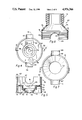
- FIG. 4 is a plan view of the base of FIG. 3;
- FIG. 5 is a cross-sectional view taken along the lines 5--5 of FIG. 4;
- FIG. 6 is a perspective view of the body of a preferred embodiment of the valve box
- FIG. 7 is a plan view of the body of FIG. 6;
- FIG. 8 is a cross-sectional view taken along lines 8--8 of FIG. 7;
- FIG. 9 is a partial cross-sectional view of a valve box assembly illustrating a valve such as that of FIG. 1 mounted in the valve box of FIGS. 3 and 6;
- FIG. 10 is a partial cross-sectional view of a valve box assembly illustrating a valve such as that of FIG. 2 mounted in the valve box of FIGS. 3 and 6.
- FIG. 11 is a partial cross-sectional view of a valve box assembly illustrating another type of vertical body valve mounted in the valve box of FIGS. 3 and 6;
- FIG. 12 is a partial cross-sectional view of a valve box assembly illustrating another type of valve mounted in the valve box of FIGS. 3 and 6.
- FIGS. 1 and 2 Typical modern plastic valves 10 and 20 are illustrated in FIGS. 1 and 2.
- the valve 10 is characterized by a horizontal cylindrical body 11 with incoming and outlet lines 13 and 15, respectively, extending on a linear and horizontal axis through the valve body 11.
- the internal valve mechanism (not shown) is operated by the rotation of the valve head 17.
- the valve 20 consists of a vertical cylindrical body 21 with incoming and outgoing lines 23 and 25, respectively, extending on a linear and horizontal axis through the valve body 21.
- the valve mechanism (not shown) is operated by the rotation of the valve head 27.
- valves 10 and 20 shown are typical of a wide variety of these two basic valves resulting from variations in the axial length and diameter of the valve body 11 or 21, variations in the diameter of the incoming and outgoing lines 13 or 23 and 15 or 25 and variations of the configuration of the valve head 17 or 27.
- the base 30 of a universal valve box for encapsulating any of this wide variety of valve configurations is illustrated.
- the base 30 is tubular and preferably, but not necessarily, cylindrical as shown. It is divided by a horizontal member 31 to define upper and lower portions 33 and 35, respectively.
- the horizontal member 31 includes a sequence of concentric steps 37, 39 and 41 which descend downwardly and inwardly into the lower portion 35 of the base 30.
- the uppermost level of the horizontal member 31 also includes diametrically opposed V-shaped seats 43 and 45 which extend from the first step 37 toward the cylindrical wall of the base 30.
- the base angle of the V-shaped seats will be between ninety and one hundred thirty-five degrees and preferably approximately one hundred twenty degrees to snugly receive a typical hex connector.
- the upper portion 33 of the base 30 also has a pair of diametrically opposed topwardly accessible notches 47 and 49 which are aligned vertically with the V-shaped seats 43 and 45.
- the notches 47 and 49 have preferably semi-circular bottoms as shown and may optionally include cradle portions 51 and 53 extending radially outwardly from the body 30.
- Preferably the notches 47 and 49 are sized to accommodate a 2" O.D. pipe or hex connector.
- the lowermost portion of the horizontal member 31 may also include an aperture 55 to facilitate drainage of undesirable substances from the valve base 30.
- the depth of each of the steps 37, 39 and 41 is coordinated with its respective concentric diameter to accommodate a wide variety of valves having vertical cylindrical bodies as illustrated in FIG. 2.
- the number of concentric steps may also be varied. Similarly, the length, depth and angle of the V-shaped seats 43 and 45 is established to accommodate a wide variety of valves having horizontal cylindrical bodies as illustrated in FIG. 1, as well as comparatively narrow valves with hex connectors mounted within the base 30. One or more of the concentric steps may be adapted as a knockout to permit accommodation of longer vertical body valves.
- the base 30 may also have an outer peripheral lip 57 along its upper edge for purposes hereinafter explained.
- the body 60 of the valve box is illustrated.
- the body 60 is a tubular member configured to securely, removably gird the upper portion 33 of the base 30.
- the body will have a cylindrical lower barrel 61 having an inner diameter substantially equal to the outer diameter of the cylindrical base 30.
- Ribs 63 may also be provided on the interior surface of the lower barrel which will cooperate with the lip 57 of the base 30 to provide a releasable interlock between the base 30 and the body 60.
- the ribs could be formed on the outer surface of the base 30 and the lip provided on the interior lower periphery of the barrel 61.
- a pair of diametrically opposed bottomwardly accessible notches 65 and 67 are provided in the lower barrel 62.
- the notches 65 and 67 are alignable with the base notches 47 and 49, have a semi-circular upper portion and may include outwardly extending saddles 69 and 71.
- the body 60 may also include an upper barrel 73 of diameter less than that of the lower barrel 61, the barrels 61 and 73 being integrally connected by an inwardly and upwardly tapering intermediate segment 75 between the two.
- the upper barrel 73 will be configured for snug disposition within the cylindrical housing which will extend from the valve box body 60 upwardly to the ground level (not shown).
- the height of the lower barrel 61 and the height and slope of the intermediate segment 75 may also be coordinated for reasons hereinafter set forth.
- FIGS. 9 through 12 illustrate the mounting of various typical horizontal and vertical body valves within the valve box.
- a horizontal body valve such as that shown in FIG. 1 is mounted with its body section 11 partly disposed within the V-shaped seats 43 and 45.
- the depth of the topwardly accessible notches 47 and 49 is established so that with the valve body 11 resting within or on the V-shaped seats 43 and 45, the inlet and outlet lines 13 and 15 extend through the diametrically opposed notches 47 and 49.
- the inlet and outlet lines 13 and 15 are preferably cradled in the cradles 51 and 53 but may be spaced from the cradles 51 and 53 if the valve body 11 rests on the seats 43 and 45.
- the valve body 60 is removably securely set over the base 30 with the bottomwardly accessible notches 65 and 67 aligned to slide over the inlet and outlet lines 13 and 15.
- the saddles 69 and 71 cooperate with the cradles 51 and 53 to partially circle or grasp the inlet and outlet lines 13 and 15.
- the body 60 is downwardly pressed onto the base 30 until the upper portions of the notches 65 and 67 come into contact with the inlet lines 13 and 15.
- a vertical body valve such as that shown in FIG. 2 is mounted in the base 30 by setting the cylindrical valve body 21 within the appropriate concentric step of the base 30.
- the valve 20 can be inserted into the cylindrical upper portion 33 of the base 30 until the inlet and outlet lines 23 and 25 or their connectors come into contact with the lower portions of the topwardly accessible notches 47 and 49.
- the bottom of the cylindrical valve body 21 will thus be seated within but not necessarily in contact with the horizontal surface of the appropriate concentric step.
- the length of the upper portion 33 of the base 30 and the depth of the notches 47 and 49 are coordinated to this purpose.
- the cradles 51 and 53 and the saddles 69 and 71 when employed, function similarly to the manner described in relation to FIG. 9. With the valve assembly disposed on the base 30, the body 60 is securely and removably pressed onto the base 30 until the upper portion of the notches 65 and 67 contact the inlet and outlet lines 23 and 25 or their connectors.
- FIG. 11 illustrates another type of vertical body valve 80 mounted on the base 30 by inserting the cylindrical valve body 81 into the appropriate concentric step of the base 30 until the bottom 83 of the valve body 81 is firmly seated on the horizontal portion of the concentric step.
- the inlet and outlet lines 85 and 87 may be seated in contact with the cradles 51 and 53 but more likely will be spaced slightly above the cradles 51 and 53 as shown.
- FIG. 12 Another type of valve 90 is illustrated in FIG. 12 to emphasize the mounting arrangement in which the hex connectors 91 and 93 associated with inlet and outlet lines 95 and 97 are firmly seated in the V-shaped seats 43 and 45 of the base 30.
- the inlet and outlet lines 95 and 97 may, but do not necessarily, come into contact with the cradles 51 and 53.
- This illustration also emphasizes the use of a knock-out 99 feature provided in the base 30.
- valve is seated in the V-shaped seats 43 and 45 as is here illustrated, or if some cases in which the height of a valve having a vertical cylindrical body is too great to be accommodated by the depth of the base 30, one or more of the concentric steps in the base 30 will be adapted as a knock-out 99 to permit the body of the valve 90 to extend through the base 30.
- the height of the lower barrel 61 and the height and slope of the intermediate section 75 of the body 60 may be coordinated so that the upper portion of the valve including the head will be restrictively located within the intermediate segment 75. This insures the proper alignment of the head with the upper barrel portion 73 so that proper access to the head can always be had through the tubular housing which extends from the top of the body 60 to the surface level (not shown). This restrictive encasement also insures that the valve will not be rotated to any appreciable extent about the axis of the inlet and outlet lines through external forces on the mounted valve system.
- the cradles 51 and 53 and saddles 69 and 71 serve to distribute forces exerted on the valve box over a greater area rather than to permit such forces to be focused on a concentrated location on the inlet or outlet lines, which could result in damage to the system.
- the outer walls of the base 30 and the body 60 need not necessarily be cylindrical.
Landscapes
- Engineering & Computer Science (AREA)
- General Engineering & Computer Science (AREA)
- Health & Medical Sciences (AREA)
- Life Sciences & Earth Sciences (AREA)
- Hydrology & Water Resources (AREA)
- Public Health (AREA)
- Water Supply & Treatment (AREA)
- Mechanical Engineering (AREA)
- Valve Housings (AREA)
Abstract
Description
Claims (17)
Priority Applications (1)
| Application Number | Priority Date | Filing Date | Title |
|---|---|---|---|
| US07/463,160 US4976366A (en) | 1990-01-10 | 1990-01-10 | Underground valve box |
Applications Claiming Priority (1)
| Application Number | Priority Date | Filing Date | Title |
|---|---|---|---|
| US07/463,160 US4976366A (en) | 1990-01-10 | 1990-01-10 | Underground valve box |
Publications (1)
| Publication Number | Publication Date |
|---|---|
| US4976366A true US4976366A (en) | 1990-12-11 |
Family
ID=23839084
Family Applications (1)
| Application Number | Title | Priority Date | Filing Date |
|---|---|---|---|
| US07/463,160 Expired - Fee Related US4976366A (en) | 1990-01-10 | 1990-01-10 | Underground valve box |
Country Status (1)
| Country | Link |
|---|---|
| US (1) | US4976366A (en) |
Cited By (18)
| Publication number | Priority date | Publication date | Assignee | Title |
|---|---|---|---|---|
| EP0564068A1 (en) * | 1992-03-30 | 1993-10-06 | Inax Corporation | Housing for a vacuum valve unit |
| US5546977A (en) * | 1994-03-08 | 1996-08-20 | Conley Corporation | Dual containment valve system |
| US5615700A (en) * | 1994-03-08 | 1997-04-01 | Conley Corporation | Double containment fitting |
| US5797415A (en) * | 1993-10-15 | 1998-08-25 | Horizon Resources Corp. | Insulating jacket for hot and cold piping systems and the method of use |
| US7004677B1 (en) | 2003-01-13 | 2006-02-28 | Orbit Irrigation Products, Inc. | Enhanced irrigation valve platform assembly |
| US20070044841A1 (en) * | 2005-09-01 | 2007-03-01 | Adaptor, Inc. | Gate valve sealing structure |
| US20070272305A1 (en) * | 2006-05-23 | 2007-11-29 | Scott Schumacher | Irrigation system valve manifold vault |
| US7389891B1 (en) * | 2000-12-18 | 2008-06-24 | The Peter Gavin Spray Trust | Septic system tank |
| USD623126S1 (en) | 2010-02-09 | 2010-09-07 | Continental Industries, Inc. | Battery, switch and voltage indicator device |
| US20110162729A1 (en) * | 2008-06-11 | 2011-07-07 | Honeywell Technologies Sarl | Gas regulating unit |
| US20110180159A1 (en) * | 2010-01-28 | 2011-07-28 | Orbit Irrigation Products, Inc. | Valve Box Platform |
| US8360265B1 (en) * | 2007-06-29 | 2013-01-29 | Jeffrey Andrews | Container and lid for sawhorse application |
| USD777547S1 (en) | 2013-03-22 | 2017-01-31 | Hubbell Incorporated | Handle clamp for an exothermic welding mold |
| US10738999B2 (en) | 2017-10-03 | 2020-08-11 | Hubbell Incorporated | Trigger devices for exothermix welds |
| US11229970B2 (en) | 2017-08-21 | 2022-01-25 | Hubbell Incorporated | Handle for exothermic mold with spring connectors |
| US11560699B1 (en) | 2022-01-31 | 2023-01-24 | Adaptor, Inc. | Curb stop structure |
| US12313206B2 (en) | 2023-09-07 | 2025-05-27 | Georg Fischer Llc | Secondary containment for operable valves |
| USD1090785S1 (en) | 2022-01-31 | 2025-08-26 | Adaptor, Inc. | Curb stop structure |
Citations (11)
| Publication number | Priority date | Publication date | Assignee | Title |
|---|---|---|---|---|
| US3367358A (en) * | 1965-11-17 | 1968-02-06 | Philip B. Rentschler | Pipe juncture covering device and applying method |
| US3392867A (en) * | 1966-01-07 | 1968-07-16 | Marvin W. Morris | Water meter cover |
| US3425456A (en) * | 1967-05-17 | 1969-02-04 | Arthur Schibig | Protective sheath for insulating pipe covering |
| US3556158A (en) * | 1967-04-26 | 1971-01-19 | Marvin Schneider | Insulator for pipe accouterments and the like |
| US3575214A (en) * | 1969-06-12 | 1971-04-20 | Jerome E Bindel | Insulated hanger assembly |
| US4162740A (en) * | 1977-09-29 | 1979-07-31 | Jones Clifford W | Valve cover |
| US4301828A (en) * | 1979-12-17 | 1981-11-24 | Martin Jr Timothy J | Protective cover device |
| US4429721A (en) * | 1982-11-10 | 1984-02-07 | Plibrico (Canada) Limited | Interlocking refractory segments |
| US4449554A (en) * | 1982-03-22 | 1984-05-22 | Busse Richard O | Universal removable insulation |
| US4716926A (en) * | 1986-02-22 | 1988-01-05 | Ludwig Jacobs | Housing for heat insulating armatures and/or flange connectors |
| US4872575A (en) * | 1987-06-30 | 1989-10-10 | Kobilan Errol D | Protective housing structure for underground devices |
-
1990
- 1990-01-10 US US07/463,160 patent/US4976366A/en not_active Expired - Fee Related
Patent Citations (11)
| Publication number | Priority date | Publication date | Assignee | Title |
|---|---|---|---|---|
| US3367358A (en) * | 1965-11-17 | 1968-02-06 | Philip B. Rentschler | Pipe juncture covering device and applying method |
| US3392867A (en) * | 1966-01-07 | 1968-07-16 | Marvin W. Morris | Water meter cover |
| US3556158A (en) * | 1967-04-26 | 1971-01-19 | Marvin Schneider | Insulator for pipe accouterments and the like |
| US3425456A (en) * | 1967-05-17 | 1969-02-04 | Arthur Schibig | Protective sheath for insulating pipe covering |
| US3575214A (en) * | 1969-06-12 | 1971-04-20 | Jerome E Bindel | Insulated hanger assembly |
| US4162740A (en) * | 1977-09-29 | 1979-07-31 | Jones Clifford W | Valve cover |
| US4301828A (en) * | 1979-12-17 | 1981-11-24 | Martin Jr Timothy J | Protective cover device |
| US4449554A (en) * | 1982-03-22 | 1984-05-22 | Busse Richard O | Universal removable insulation |
| US4429721A (en) * | 1982-11-10 | 1984-02-07 | Plibrico (Canada) Limited | Interlocking refractory segments |
| US4716926A (en) * | 1986-02-22 | 1988-01-05 | Ludwig Jacobs | Housing for heat insulating armatures and/or flange connectors |
| US4872575A (en) * | 1987-06-30 | 1989-10-10 | Kobilan Errol D | Protective housing structure for underground devices |
Cited By (28)
| Publication number | Priority date | Publication date | Assignee | Title |
|---|---|---|---|---|
| US5291917A (en) * | 1992-03-30 | 1994-03-08 | Inax Corporation | Housing for a vacuum valve unit |
| EP0564068A1 (en) * | 1992-03-30 | 1993-10-06 | Inax Corporation | Housing for a vacuum valve unit |
| US5797415A (en) * | 1993-10-15 | 1998-08-25 | Horizon Resources Corp. | Insulating jacket for hot and cold piping systems and the method of use |
| US5546977A (en) * | 1994-03-08 | 1996-08-20 | Conley Corporation | Dual containment valve system |
| US5615700A (en) * | 1994-03-08 | 1997-04-01 | Conley Corporation | Double containment fitting |
| US7389891B1 (en) * | 2000-12-18 | 2008-06-24 | The Peter Gavin Spray Trust | Septic system tank |
| US7004677B1 (en) | 2003-01-13 | 2006-02-28 | Orbit Irrigation Products, Inc. | Enhanced irrigation valve platform assembly |
| US20070044841A1 (en) * | 2005-09-01 | 2007-03-01 | Adaptor, Inc. | Gate valve sealing structure |
| US7703474B2 (en) * | 2005-09-01 | 2010-04-27 | Adaptor, Inc. | Gate valve sealing structure |
| US20070272305A1 (en) * | 2006-05-23 | 2007-11-29 | Scott Schumacher | Irrigation system valve manifold vault |
| US9205953B2 (en) | 2007-06-29 | 2015-12-08 | Jeffrey Andrews | Container and lid for sawhorse application |
| US8360265B1 (en) * | 2007-06-29 | 2013-01-29 | Jeffrey Andrews | Container and lid for sawhorse application |
| US20110162729A1 (en) * | 2008-06-11 | 2011-07-07 | Honeywell Technologies Sarl | Gas regulating unit |
| US9163741B2 (en) * | 2008-06-11 | 2015-10-20 | Honeywell Technologies Sarl | Gas regulating unit |
| US8567432B2 (en) | 2010-01-28 | 2013-10-29 | Orbit Irrigation Products, Inc. | Valve box platform |
| US20110180159A1 (en) * | 2010-01-28 | 2011-07-28 | Orbit Irrigation Products, Inc. | Valve Box Platform |
| US9133606B2 (en) | 2010-01-28 | 2015-09-15 | Orbit Irrigation Products, Inc. | Valve box platform |
| USD623126S1 (en) | 2010-02-09 | 2010-09-07 | Continental Industries, Inc. | Battery, switch and voltage indicator device |
| USD777547S1 (en) | 2013-03-22 | 2017-01-31 | Hubbell Incorporated | Handle clamp for an exothermic welding mold |
| USD805366S1 (en) | 2013-03-22 | 2017-12-19 | Hubbell Incorporated | Handle clamp for an exothermic welding mold |
| US11229970B2 (en) | 2017-08-21 | 2022-01-25 | Hubbell Incorporated | Handle for exothermic mold with spring connectors |
| US11724327B2 (en) | 2017-08-21 | 2023-08-15 | Hubbell Incorporated | Handle for exothermic mold with spring connectors |
| US10935239B2 (en) | 2017-10-03 | 2021-03-02 | Hubbell Incorporated | Trigger devices for exothermic welds |
| US11441776B2 (en) | 2017-10-03 | 2022-09-13 | Hubbell Incorporated | Trigger devices for exothermic welds |
| US10738999B2 (en) | 2017-10-03 | 2020-08-11 | Hubbell Incorporated | Trigger devices for exothermix welds |
| US11560699B1 (en) | 2022-01-31 | 2023-01-24 | Adaptor, Inc. | Curb stop structure |
| USD1090785S1 (en) | 2022-01-31 | 2025-08-26 | Adaptor, Inc. | Curb stop structure |
| US12313206B2 (en) | 2023-09-07 | 2025-05-27 | Georg Fischer Llc | Secondary containment for operable valves |
Similar Documents
| Publication | Publication Date | Title |
|---|---|---|
| US4976366A (en) | Underground valve box | |
| US4757641A (en) | Decorative device for camouflaging a well casing | |
| US4331832A (en) | Electrical outlet box | |
| US6167673B1 (en) | Utility pole | |
| US5076456A (en) | Containment sump with stackable extensions | |
| US4230234A (en) | Meter box assembly | |
| US3027416A (en) | Electrical outlet box | |
| US5468105A (en) | Ceiling insert | |
| US4344645A (en) | Tee-type leg bracket | |
| US20210296874A1 (en) | Sealed cable passage | |
| US4775073A (en) | Multi-purpose fitting system | |
| US4023699A (en) | Cap assembly for multi-size well casings | |
| NZ238758A (en) | Underground meter box. | |
| US3349946A (en) | Electric outlet box | |
| EP1335462B1 (en) | Inside column for low voltage electrical connections | |
| US3958629A (en) | Fluid receptacle having at least one heat exchanging unit detachably mounted therein | |
| US20090050625A1 (en) | Fuel inlet device and part therefor | |
| US5535915A (en) | Meter pit | |
| US4858076A (en) | Converter | |
| CA2315561A1 (en) | Arrangement with a female pipe adapter, a female pipe adapter, a bottom pan, an opening design, and a mould core | |
| CA2291539C (en) | Attachment structure for vessel fitting | |
| EP3496219B1 (en) | Connection casing | |
| US2770715A (en) | Weatherproof and vapor-tight fixture | |
| US20060042174A1 (en) | Modular riser base | |
| US3542940A (en) | Service fittings |
Legal Events
| Date | Code | Title | Description |
|---|---|---|---|
| FEPP | Fee payment procedure |
Free format text: PAYOR NUMBER ASSIGNED (ORIGINAL EVENT CODE: ASPN); ENTITY STATUS OF PATENT OWNER: LARGE ENTITY |
|
| AS | Assignment |
Owner name: RUSSELL SALES CO., INC., OKLAHOMA Free format text: ASSIGNMENT OF ASSIGNORS INTEREST;ASSIGNOR:RUSSELL, JIM L.;REEL/FRAME:006615/0769 Effective date: 19920901 |
|
| FEPP | Fee payment procedure |
Free format text: PAT HLDR NO LONGER CLAIMS SMALL ENT STAT AS INDIV INVENTOR (ORIGINAL EVENT CODE: LSM1); ENTITY STATUS OF PATENT OWNER: LARGE ENTITY Free format text: PAYOR NUMBER ASSIGNED (ORIGINAL EVENT CODE: ASPN); ENTITY STATUS OF PATENT OWNER: LARGE ENTITY Free format text: PAYER NUMBER DE-ASSIGNED (ORIGINAL EVENT CODE: RMPN); ENTITY STATUS OF PATENT OWNER: LARGE ENTITY |
|
| FPAY | Fee payment |
Year of fee payment: 4 |
|
| AS | Assignment |
Owner name: CONTINENTAL INDUSTRIES, INC., OKLAHOMA Free format text: ASSIGNMENT OF ASSIGNORS INTEREST;ASSIGNOR:RUSSELL SALES COMPANY, INC.;REEL/FRAME:006965/0540 Effective date: 19930715 |
|
| REMI | Maintenance fee reminder mailed | ||
| LAPS | Lapse for failure to pay maintenance fees | ||
| FP | Lapsed due to failure to pay maintenance fee |
Effective date: 19981211 |
|
| STCH | Information on status: patent discontinuation |
Free format text: PATENT EXPIRED DUE TO NONPAYMENT OF MAINTENANCE FEES UNDER 37 CFR 1.362 |