US4974409A - Process for producing a twisted yarn feed spool - Google Patents
Process for producing a twisted yarn feed spool Download PDFInfo
- Publication number
- US4974409A US4974409A US07/313,538 US31353889A US4974409A US 4974409 A US4974409 A US 4974409A US 31353889 A US31353889 A US 31353889A US 4974409 A US4974409 A US 4974409A
- Authority
- US
- United States
- Prior art keywords
- slivers
- prestrengthened
- fiber ends
- core
- twisting
- Prior art date
- Legal status (The legal status is an assumption and is not a legal conclusion. Google has not performed a legal analysis and makes no representation as to the accuracy of the status listed.)
- Expired - Fee Related
Links
- 238000000034 method Methods 0.000 title claims abstract description 19
- 239000000835 fiber Substances 0.000 claims abstract description 39
- 238000004804 winding Methods 0.000 claims description 8
- 238000004519 manufacturing process Methods 0.000 claims 1
- 208000027418 Wounds and injury Diseases 0.000 description 24
- 208000004221 Multiple Trauma Diseases 0.000 description 2
- 238000007664 blowing Methods 0.000 description 2
- 230000000694 effects Effects 0.000 description 2
- 239000002657 fibrous material Substances 0.000 description 1
- 238000002347 injection Methods 0.000 description 1
- 239000007924 injection Substances 0.000 description 1
- 238000012806 monitoring device Methods 0.000 description 1
- 239000004753 textile Substances 0.000 description 1
- 230000003313 weakening effect Effects 0.000 description 1
Images


Classifications
-
- D—TEXTILES; PAPER
- D02—YARNS; MECHANICAL FINISHING OF YARNS OR ROPES; WARPING OR BEAMING
- D02G—CRIMPING OR CURLING FIBRES, FILAMENTS, THREADS, OR YARNS; YARNS OR THREADS
- D02G3/00—Yarns or threads, e.g. fancy yarns; Processes or apparatus for the production thereof, not otherwise provided for
- D02G3/22—Yarns or threads characterised by constructional features, e.g. blending, filament/fibre
- D02G3/26—Yarns or threads characterised by constructional features, e.g. blending, filament/fibre with characteristics dependent on the amount or direction of twist
- D02G3/28—Doubled, plied, or cabled threads
- D02G3/281—Doubled, plied, or cabled threads using one drawing frame for two slivers and twisting of the slivers to a single yarn, i.e. spin-twisting
-
- B—PERFORMING OPERATIONS; TRANSPORTING
- B65—CONVEYING; PACKING; STORING; HANDLING THIN OR FILAMENTARY MATERIAL
- B65H—HANDLING THIN OR FILAMENTARY MATERIAL, e.g. SHEETS, WEBS, CABLES
- B65H54/00—Winding, coiling, or depositing filamentary material
- B65H54/02—Winding and traversing material on to reels, bobbins, tubes, or like package cores or formers
- B65H54/026—Doubling winders, i.e. for winding two or more parallel yarns on a bobbin, e.g. in preparation for twisting or weaving
-
- D—TEXTILES; PAPER
- D01—NATURAL OR MAN-MADE THREADS OR FIBRES; SPINNING
- D01H—SPINNING OR TWISTING
- D01H1/00—Spinning or twisting machines in which the product is wound-up continuously
- D01H1/11—Spinning by false-twisting
- D01H1/115—Spinning by false-twisting using pneumatic means
-
- B—PERFORMING OPERATIONS; TRANSPORTING
- B65—CONVEYING; PACKING; STORING; HANDLING THIN OR FILAMENTARY MATERIAL
- B65H—HANDLING THIN OR FILAMENTARY MATERIAL, e.g. SHEETS, WEBS, CABLES
- B65H2701/00—Handled material; Storage means
- B65H2701/30—Handled filamentary material
- B65H2701/31—Textiles threads or artificial strands of filaments
Definitions
- the invention relates to a process and apparatus for producing a twisted yarn from two slivers that are drawn to the desired size and are subsequently prestrengthened by means of pneumatic false twisting, the fiber ends being wound around the essentially unturned core, after which the prestrengthened slivers are twisted together with one another in such a way that the twisting turn is opposed to the winding-around direction, and to a feed spool for the twisting.
- the invention also relates to the twisted yarn feed spool formed by the process.
- the twisting turn is opposed to the winding-around direction of the fiber ends so that during the twisting, the bundling is weakened that is obtained by the winding-around of the fiber ends. Since, however, in the case of the known process, the fiber ends are wound around in the form of spirals, i.e., essentially in a radial plane with respect to the core, this weakening of the bundling effect can hardly be achieved. In the case of the known process, it is therefore provided that wind-around fibers are wound around less than 50% and preferably less than 30% of the length of the slivers.
- the invention is based on an objective of providing a process of the initially mentioned type in which a sufficiently firm, but at the same time voluminous yarn is obtained that has a high uniformity.
- the advantageous effect is achieved that the slivers are prestrengthened over their length in a more uniform way.
- the special advantage is achieved that the areas that were surrounded by the winding during the prestrengthening, during the subsequent introduction of the twist, are loosened up again, because the winding-around is practically undone.
- the predominant part of the fiber ends that were wound around the core of the sliver during the prestrengthening form helixes of an angle of slope of 45° and more. This has the result that also these areas are reduced in which the winding-around sliver ends wind mutually around one another so that the opening-up of these windings is improved further during the twisting.
- FIG. 1 is a diagrammatic representation of an arrangement for carrying out the process according to the invention
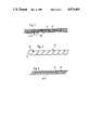
- FIG. 2 is a very enlarged diagrammatic representation of a prestrengthened sliver formed in accordance with a preferred embodiment of the present invention with a helical winding around of radially outward fibers around the core of sliver fibers;
- FIG. 2A is a schematic view of section 2A of FIG. 2 and showing the helical winding angle of the radially outward wound around fibers;
- FIG. 3 is an enlarged diagrammatic representation of a twisted yarn formed in accordance with a preferred embodiment of the present invention using a pair of prestrengthened slivers according to FIG. 2;
- FIG. 4 is an enlarged, diagrammatic representation of a component of the finished twisted yarn of FIG. 3 depicting the twisting turn and orientation of the prestrengthened wrapped around fibers in the finished twisted yarn.
- FIG. 1 The arrangement shown in FIG. 1, of which a machine has a plurality of similar devices arranged next to one another, contains, in tandem in moving direction of the fiber material to be processed, a drafting frame 1, a twisting zone 2, a withdrawal device 3 and a spooling or winding device 4.
- a drafting frame 1 a twisting zone 2
- a withdrawal device 3 a withdrawal device 3
- a spooling or winding device 4 By means of this arrangement, two slivers 6, 9 are drawn to the desired size and prestrengthened and subsequently are wound jointly in a multiple-wound form onto a cross-wound spool 50.
- the slivers 6, 9 are taken from feed spools 5, 8 or alternatively out of sliver cans and introduced into the drafting frame 1.
- the drafting frame 1 contains bottom cylinders that are not shown and that pass through and are driven in the longitudinal direction of the machine, to which top rollers (12, 15), (13, 16) and (14, 17) that are developed as pressure roller pairs are assigned for the two slivers 6, 9.
- top rollers (12, 15), (13, 16) and (14, 17) that are developed as pressure roller pairs are assigned for the two slivers 6, 9.
- tape guides are provided in the main drafting zone.
- the shafts 18, 19, 20 of the pressure roller pairs are disposed in a joint weighting arm 21 that can be swivelled around a rod 22 that passes through in the longitudinal direction of the machine so that the drafting frame 1 can be opened.
- Sliver guards 23, 24 are connected in front of the drafting frame 1 that control sliver clamps 25, 26 arranged in the feeding area in front of the feeding top rollers 12, 15, and that monitor the feeding of a sliver 6, 9. If it is determined that a sliver 6, 9 is absent, both sliver clamps 25, 26 are actuated so that the continued process is interrupted.
- a total of four air nozzles 28, 29, 32 and 33 are arranged in pairs on a joint supporting plate 27.
- two air nozzles respectively that are arranged behind one another are assigned to respective slivers 6, 9.
- the air nozzles 28, 32 that directly follow the drafting frame 1 and that are connected to compressed-air supply lines 30, 34, are developed as so-called intake nozzles.
- These nozzles 28, 32 generate an injection air flow that acts essentially in the moving direction (A, B) of the slivers 6, 9 and provide the slivers 6, 9 with practically no twist, or no more than a slight twist.
- the air nozzles 29, 33 that follow the air nozzles 28, 32 and that are connected to compressed-air supply lines 31, 35, are constructed as so-called false-twisting nozzles that provide the slivers 6, 9, that were drawn to the desired size in the drafting frame 1, with a false twist by means of an air whirl that is generated in them and has a predetermined direction.
- both slivers 6, 9, receive a false twist in the same direction in the air nozzles 29, 33.
- the slivers 6, 9 receive a prestrengthening that will be explained in greater detail below.
- the wind-on device 4 that follows contains a yarn guide that traverses in the direction of the Arrows (C, D) and in front of which a compensating device 39 is connected that compensates the different lengths of the formed double yarn 11 that are present during the traversing.
- a yarn monitoring device 41, 42 is also arranged that is designed in such a way that it responds as early as during a breakage of a prestrengthened sliver 7, 10 and then actuates both sliver clamps 25, 26 so that not only one of the prestrengthened slivers 7, 10 alone is wound onto the cross-wound spool 50.
- the cross-wound spool 50 onto which the two prestrengthened yarn components 7, 10 are wound in a multiple-wound way as a double yarn 11, is used as a feed spool for a subsequent twisting by means of a known twisting machine, such as a double-twist frame.
- the prestrengthening in the twisting zone 2 takes place in such a way that fiber ends of fibers anchored in the slivers 6, 9 are spread away from the slivers 6, 9 and are wound around the core of the sliver 7, 10.
- the twisting zone 2 is operated in such a way that the fiber ends 44 are wound around the core 43, that consists essentially of unturned fibers that are disposed in parallel to one another, this winding taking place in the form of steep helixes.
- the winding-around must be distributed as uniformly as possible over the length of the slivers 7, 10.
- the steepness of the helixes can be affected particularly by the blowing direction of the blow-out openings of the air nozzle 29, 33, as well as the applied excess pressure.
- the blowing direction may be selected in such a way that the openings can blow out into a joint radial plane or have a component in the moving direction (A, B) of the slivers 6, 9.
- the steepness of the helixes can be controlled by the passing-through speed of the slivers 6, 9 by means of which these are guided through the twisting zone 2.
- the yarn tension in the twisting zone 2 that is determined by the delivery speed at the outlet of the drafting frame 1 and the withdrawal speed of the withdrawal device 3.
- This speed ratio is dimensioned in such a way that a negative draft of about 0% to 3% exists in the twisting zone. Particularly, by the adjustment of this negative draft, it is possible to influence the number of the fiber ends that are wound around.
- the winding-around of fiber ends and thus the steepness of the helixes can be influenced by frictional relationships, i.e., by the frictional relationships between the interior walls, particularly of the air nozzles 29, 33, and the fibers.
- FIG. 2A schematically depicts the steepness angle A between the radius of the sliver (axis y--y) and the vertical inclination of the wrapped around fiber ends 44.
- the x--x axis of FIG. 1A corresponds to the longitudinal direction of the sliver core 43. In especially preferred embodiments, this helix angle is 45° or more.
- the twisted yarn 45 that consists of two strands 46, 47 of prestrengthened yarn or stress is produced by means of a twisting turn that is opposed to the winding-around direction of the fiber ends 44. During the twisting, not only the twisted strands 46, 47 are wound around one another, but a turn is also introduced into the twisted strands 46, 47.
- a twisted yarn that is produced in this way has sufficient strength and distinguishes itself mainly by the fact that it is very voluminous and uniform.
- a primary advantage is that this yarn has an excellent textile feel.
Landscapes
- Engineering & Computer Science (AREA)
- Textile Engineering (AREA)
- Mechanical Engineering (AREA)
- Yarns And Mechanical Finishing Of Yarns Or Ropes (AREA)
- Spinning Or Twisting Of Yarns (AREA)
- Filamentary Materials, Packages, And Safety Devices Therefor (AREA)
Abstract
In the case of a process for producing a twisted yarn from slivers that are drawn to the desired size and subsequently are prestrengthened by means of pneumatic false twisting, it is provided that the fiber ends in the form of helixes are wound around the core with such a steep slope that, during the twisting, the fiber ends that were previously wound around the core are wound off the core as much as possible.
Description
The invention relates to a process and apparatus for producing a twisted yarn from two slivers that are drawn to the desired size and are subsequently prestrengthened by means of pneumatic false twisting, the fiber ends being wound around the essentially unturned core, after which the prestrengthened slivers are twisted together with one another in such a way that the twisting turn is opposed to the winding-around direction, and to a feed spool for the twisting. The invention also relates to the twisted yarn feed spool formed by the process.
It is known (EP-A-38 143) to draw two slivers in a drafting frame to the desired size. Subsequently, these slivers, by means of pneumatic false twisting, are provided with a prestrengthening by means of which fiber ends are wound around the essentially unturned core of the slivers. The resulting prestrengthening of the slivers is so low that they cannot be used as individual threads or individual yarns. In the case of the known process, it is provided that the resistance to tearing of the finished twisted yarn is between 150% and 250% of the doubled, not yet twisted-together individual component. In the case of the known process, it is also provided that the twisting turn is opposed to the winding-around direction of the fiber ends so that during the twisting, the bundling is weakened that is obtained by the winding-around of the fiber ends. Since, however, in the case of the known process, the fiber ends are wound around in the form of spirals, i.e., essentially in a radial plane with respect to the core, this weakening of the bundling effect can hardly be achieved. In the case of the known process, it is therefore provided that wind-around fibers are wound around less than 50% and preferably less than 30% of the length of the slivers. This has the objective that subsequently, after the twisting, a yarn is created that is not very hard, like the known air yarns, but has an improved feel. However, in the case of this process, a relatively uneven twisted yarn is obtained that in the areas, in which the winding-around is present, has a hard feel but otherwise has a soft feel.
The invention is based on an objective of providing a process of the initially mentioned type in which a sufficiently firm, but at the same time voluminous yarn is obtained that has a high uniformity.
This objective is achieved by the fact that the fiber ends, in the form of helixes, are wound around the core with such a steep slope during the prestrengthening by pneumatic false twisting that, during the subsequent yarn twisting operation, the fiber ends that were previously wound around the core are as much as possible wound off the core.
By means of the helical winding-around during the prestrengthening, the advantageous effect is achieved that the slivers are prestrengthened over their length in a more uniform way. In addition, the special advantage is achieved that the areas that were surrounded by the winding during the prestrengthening, during the subsequent introduction of the twist, are loosened up again, because the winding-around is practically undone.
In a further development of the invention, it is provided that the predominant part of the fiber ends that were wound around the core of the sliver during the prestrengthening form helixes of an angle of slope of 45° and more. This has the result that also these areas are reduced in which the winding-around sliver ends wind mutually around one another so that the opening-up of these windings is improved further during the twisting.
In a further development of the invention, it is provided that, during the prestrengthening, fiber ends are wound around the core of each of the slivers over the predominant part of the length and as uniformly as possible. As a result, the uniformity of the prestrengthened slivers and mainly the uniformity of the twisted yarn obtained later is improved significantly.
Other objects, advantages and novel features of the present invention will become apparent from the following detailed description of the invention when considered in conjunction with the accompanying drawings.
FIG. 1 is a diagrammatic representation of an arrangement for carrying out the process according to the invention;
FIG. 2 is a very enlarged diagrammatic representation of a prestrengthened sliver formed in accordance with a preferred embodiment of the present invention with a helical winding around of radially outward fibers around the core of sliver fibers;
FIG. 2A is a schematic view of section 2A of FIG. 2 and showing the helical winding angle of the radially outward wound around fibers;
FIG. 3 is an enlarged diagrammatic representation of a twisted yarn formed in accordance with a preferred embodiment of the present invention using a pair of prestrengthened slivers according to FIG. 2; and
FIG. 4 is an enlarged, diagrammatic representation of a component of the finished twisted yarn of FIG. 3 depicting the twisting turn and orientation of the prestrengthened wrapped around fibers in the finished twisted yarn.
The arrangement shown in FIG. 1, of which a machine has a plurality of similar devices arranged next to one another, contains, in tandem in moving direction of the fiber material to be processed, a drafting frame 1, a twisting zone 2, a withdrawal device 3 and a spooling or winding device 4. By means of this arrangement, two slivers 6, 9 are drawn to the desired size and prestrengthened and subsequently are wound jointly in a multiple-wound form onto a cross-wound spool 50.
The slivers 6, 9 are taken from feed spools 5, 8 or alternatively out of sliver cans and introduced into the drafting frame 1.
The drafting frame 1 contains bottom cylinders that are not shown and that pass through and are driven in the longitudinal direction of the machine, to which top rollers (12, 15), (13, 16) and (14, 17) that are developed as pressure roller pairs are assigned for the two slivers 6, 9. In the main drafting zone, tape guides are provided. The shafts 18, 19, 20 of the pressure roller pairs are disposed in a joint weighting arm 21 that can be swivelled around a rod 22 that passes through in the longitudinal direction of the machine so that the drafting frame 1 can be opened. Sliver guards 23, 24 are connected in front of the drafting frame 1 that control sliver clamps 25, 26 arranged in the feeding area in front of the feeding top rollers 12, 15, and that monitor the feeding of a sliver 6, 9. If it is determined that a sliver 6, 9 is absent, both sliver clamps 25, 26 are actuated so that the continued process is interrupted.
In the area of a twisting zone 2, a total of four air nozzles 28, 29, 32 and 33 are arranged in pairs on a joint supporting plate 27. Of these, two air nozzles respectively that are arranged behind one another are assigned to respective slivers 6, 9. The air nozzles 28, 32 that directly follow the drafting frame 1 and that are connected to compressed- air supply lines 30, 34, are developed as so-called intake nozzles. These nozzles 28, 32 generate an injection air flow that acts essentially in the moving direction (A, B) of the slivers 6, 9 and provide the slivers 6, 9 with practically no twist, or no more than a slight twist.
The air nozzles 29, 33 that follow the air nozzles 28, 32 and that are connected to compressed- air supply lines 31, 35, are constructed as so-called false-twisting nozzles that provide the slivers 6, 9, that were drawn to the desired size in the drafting frame 1, with a false twist by means of an air whirl that is generated in them and has a predetermined direction. In this case, both slivers 6, 9, receive a false twist in the same direction in the air nozzles 29, 33. Within the twisting zone 2, the slivers 6, 9 receive a prestrengthening that will be explained in greater detail below.
The air nozzles 28, 29; 32, 33 are arranged so that they converge in a V-shape and so that the prestrengthened slivers 7, 10 can approach one another as early as in the area of the false-twisting zone 2. These prestrengthened slivers 7, 10 are guided subsequently by means of yarn guides 36, 37 farther toward one another so that they move next to one another at a close distance. The yarn guides 36, 37 are followed by the withdrawal device 3 that comprises a bottom cylinder that is not shown and passes through and is driven in the longitudinal direction of the machine, a pressure roller 38 being assigned to this bottom cylinder at each arrangement that is elastically pressed against it.
The wind-on device 4 that follows contains a yarn guide that traverses in the direction of the Arrows (C, D) and in front of which a compensating device 39 is connected that compensates the different lengths of the formed double yarn 11 that are present during the traversing.
In the area behind the withdrawal device 3, a yarn monitoring device 41, 42 is also arranged that is designed in such a way that it responds as early as during a breakage of a prestrengthened sliver 7, 10 and then actuates both sliver clamps 25, 26 so that not only one of the prestrengthened slivers 7, 10 alone is wound onto the cross-wound spool 50.
The cross-wound spool 50, onto which the two prestrengthened yarn components 7, 10 are wound in a multiple-wound way as a double yarn 11, is used as a feed spool for a subsequent twisting by means of a known twisting machine, such as a double-twist frame.
The prestrengthening in the twisting zone 2 takes place in such a way that fiber ends of fibers anchored in the slivers 6, 9 are spread away from the slivers 6, 9 and are wound around the core of the sliver 7, 10.
As shown in FIG. 2, the twisting zone 2 is operated in such a way that the fiber ends 44 are wound around the core 43, that consists essentially of unturned fibers that are disposed in parallel to one another, this winding taking place in the form of steep helixes. In this case, it is endeavored that, on the one hand, not too many fiber ends 44 are spread away and wound around the core 43, while, on the other hand, the winding-around must be distributed as uniformly as possible over the length of the slivers 7, 10. The steepness of the helixes can be affected particularly by the blowing direction of the blow-out openings of the air nozzle 29, 33, as well as the applied excess pressure. In this case, the blowing direction may be selected in such a way that the openings can blow out into a joint radial plane or have a component in the moving direction (A, B) of the slivers 6, 9. In addition, the steepness of the helixes can be controlled by the passing-through speed of the slivers 6, 9 by means of which these are guided through the twisting zone 2. Also important is the yarn tension in the twisting zone 2 that is determined by the delivery speed at the outlet of the drafting frame 1 and the withdrawal speed of the withdrawal device 3. This speed ratio is dimensioned in such a way that a negative draft of about 0% to 3% exists in the twisting zone. Particularly, by the adjustment of this negative draft, it is possible to influence the number of the fiber ends that are wound around. In addition, the winding-around of fiber ends and thus the steepness of the helixes can be influenced by frictional relationships, i.e., by the frictional relationships between the interior walls, particularly of the air nozzles 29, 33, and the fibers.
FIG. 2A schematically depicts the steepness angle A between the radius of the sliver (axis y--y) and the vertical inclination of the wrapped around fiber ends 44. The x--x axis of FIG. 1A corresponds to the longitudinal direction of the sliver core 43. In especially preferred embodiments, this helix angle is 45° or more.
In practice, it is possible to examine the winding-around and the steepness of the helixes with which the fiber ends 44 are wound around the core 43, for example on yarn samples by means of a microscope, and then to adjust one or several of the above-mentioned parameters.
The two yarn components 7, 10, that were wound on spool 50 as a double yarn 11, subsequently are processed into a twisted yarn 45, as shown very diagrammatically in FIG. 3. The twisted yarn 45 that consists of two strands 46, 47 of prestrengthened yarn or stress is produced by means of a twisting turn that is opposed to the winding-around direction of the fiber ends 44. During the twisting, not only the twisted strands 46, 47 are wound around one another, but a turn is also introduced into the twisted strands 46, 47.
By means of this twisting turn, it is endeavored, as shown in FIG. 4 for one strand 46, 47 of twisted yarn, that the fibers 48 of the previously unturned core 43 have a twist. By means of this twist, the fiber ends 44 that were previously wound around the unturned core 43, see FIG. 2, are wound off so that then they extend essentially in longitudinal direction of the strand 46, 47 of twisted yarn and are located there as fiber ends 49. These fiber ends 49 that, with their beginning, are bound into the respective slivers, during the twisting, are also bound into the twisted yarn 45 so that they are not exposed.
A twisted yarn that is produced in this way has sufficient strength and distinguishes itself mainly by the fact that it is very voluminous and uniform. A primary advantage is that this yarn has an excellent textile feel.
Although the present invention has been described and illustrated in detail, it is to be clearly understood that the same is by way of illustration and example only, and is not to be taken by way of limitation. The spirit and scope of the present invention are to be limited only by the terms of the appended claims.
Claims (6)
1. A process for manufacturing a feed spool of prestrengthened slivers for a subsequent yarn twisting operation, comprising:
forming a prestrengthened sliver comprising a core made up of core fibers extending in a longitudinal direction of the prestrengthened sliver, said forming including winding fiber ends around the core in a helical manner with a predominate part of the fiber ends extending at a helical angle of slope with respect to a radial plane through the core which is 45° and greater,
wherein said fiber ends are wound around continuously and uniformly along the length of the respective cores to facilitate a subsequent yarn twisting operation on the prestrengthened sliver with the fiber ends wound around the core being substantially wound off the core.
2. A process according to claim 1, comprising forming a second prestrengthened sliver by a similar process so that two prestrengthened slivers are formed in side-by-side parallel relationship with one another.
3. A process according to claim 2, wherein the fiber ends are wound around both cores in the same direction.
4. A process according to claim 2, wherein said forming includes pneumatic false twisting, further comprising twisting the prestrengthened slivers together with one another with a twisting turn opposed to the winding around direction of the fiber ends during the pneumatic false twisting such that at least some of the fiber ends previously helically wound around the cores are wound off the respective cores and extend substantially longitudinally of the twisted yarn comprised of the two slivers together.
5. A process according to claim 4, wherein drawing and prestrengthening is performed simultaneously for said two slivers with said slivers traveling in side-by-side relationship through a common drawing and prestrengthening unit, and wherein said prestrengthened slivers are wound onto a feed spool in side-by-side parallel relationship.
6. A process according to claim 2, wherein drawing and prestrengthening is performed simultaneously for said two slivers with said slivers traveling in side-by-side relationship through a common drawing and prestrengthening unit, and wherein said prestrengthened slivers are wound onto a feed spool in side-by-side parallel relationship.
Applications Claiming Priority (2)
| Application Number | Priority Date | Filing Date | Title |
|---|---|---|---|
| DE3700186 | 1987-01-06 | ||
| DE3700186A DE3700186C2 (en) | 1987-01-06 | 1987-01-06 | Method of making a twine and supply spool for twisting |
Related Parent Applications (1)
| Application Number | Title | Priority Date | Filing Date |
|---|---|---|---|
| US07/140,760 Division US4854523A (en) | 1987-01-06 | 1988-01-04 | Twisted yarn feed spool and process for producing same |
Publications (1)
| Publication Number | Publication Date |
|---|---|
| US4974409A true US4974409A (en) | 1990-12-04 |
Family
ID=6318471
Family Applications (2)
| Application Number | Title | Priority Date | Filing Date |
|---|---|---|---|
| US07/140,760 Expired - Fee Related US4854523A (en) | 1987-01-06 | 1988-01-04 | Twisted yarn feed spool and process for producing same |
| US07/313,538 Expired - Fee Related US4974409A (en) | 1987-01-06 | 1989-02-22 | Process for producing a twisted yarn feed spool |
Family Applications Before (1)
| Application Number | Title | Priority Date | Filing Date |
|---|---|---|---|
| US07/140,760 Expired - Fee Related US4854523A (en) | 1987-01-06 | 1988-01-04 | Twisted yarn feed spool and process for producing same |
Country Status (3)
| Country | Link |
|---|---|
| US (2) | US4854523A (en) |
| JP (1) | JPS63303129A (en) |
| DE (1) | DE3700186C2 (en) |
Families Citing this family (8)
| Publication number | Priority date | Publication date | Assignee | Title |
|---|---|---|---|---|
| JPH0778291B2 (en) * | 1988-07-11 | 1995-08-23 | 村田機械株式会社 | Yarn manufacturing method and manufacturing apparatus |
| DE3935705C2 (en) * | 1988-10-26 | 1996-02-29 | Murata Machinery Ltd | Method for producing a multiple thread consisting of spun threads and device for carrying out the method |
| US5566539A (en) * | 1990-07-20 | 1996-10-22 | Binder; Rolf | Method and apparatus for repairing a yarn breakage in a pair of spinning units |
| JPH0525714A (en) * | 1991-07-11 | 1993-02-02 | Murata Mach Ltd | Production device of three-layer structure yarn |
| JPH0525715A (en) * | 1991-07-12 | 1993-02-02 | Murata Mach Ltd | Production device of blend yarn |
| US5749212A (en) * | 1995-06-06 | 1998-05-12 | Dixy Yarns, Inc. | Elastomeric core/staple fiber wrap yarn |
| CA2178017A1 (en) * | 1995-06-06 | 1996-12-07 | John Joseph Matthews Rees | System for forming elastomeric core/staple fiber wrap yarn using a spinning machine |
| IT1298921B1 (en) * | 1998-02-20 | 2000-02-07 | Arratex Srl | PROCEDURE FOR OBTAINING A COMBINED WIRE THROUGH INDEPENDENT WIRES |
Citations (5)
| Publication number | Priority date | Publication date | Assignee | Title |
|---|---|---|---|---|
| US4003194A (en) * | 1973-04-10 | 1977-01-18 | Toray Industries, Inc. | Method and apparatus for producing helically wrapped yarn |
| US4142354A (en) * | 1977-03-24 | 1979-03-06 | Murata Kikai Kabushiki Kaisha | Direct spinning apparatus |
| US4183202A (en) * | 1976-03-04 | 1980-01-15 | Murata Kikai Kabushiki Kaisha | Method and apparatus for producing spun yarn |
| US4484436A (en) * | 1980-04-01 | 1984-11-27 | Toray Industries, Inc. | Process for producing a twisted yarn |
| US4598537A (en) * | 1982-05-05 | 1986-07-08 | Elitex, Koncern Textilniho Strojirenstvi | Method of manufacturing core yarns from fiber bands |
-
1987
- 1987-01-06 DE DE3700186A patent/DE3700186C2/en not_active Expired - Fee Related
- 1987-12-01 JP JP62304404A patent/JPS63303129A/en active Pending
-
1988
- 1988-01-04 US US07/140,760 patent/US4854523A/en not_active Expired - Fee Related
-
1989
- 1989-02-22 US US07/313,538 patent/US4974409A/en not_active Expired - Fee Related
Patent Citations (5)
| Publication number | Priority date | Publication date | Assignee | Title |
|---|---|---|---|---|
| US4003194A (en) * | 1973-04-10 | 1977-01-18 | Toray Industries, Inc. | Method and apparatus for producing helically wrapped yarn |
| US4183202A (en) * | 1976-03-04 | 1980-01-15 | Murata Kikai Kabushiki Kaisha | Method and apparatus for producing spun yarn |
| US4142354A (en) * | 1977-03-24 | 1979-03-06 | Murata Kikai Kabushiki Kaisha | Direct spinning apparatus |
| US4484436A (en) * | 1980-04-01 | 1984-11-27 | Toray Industries, Inc. | Process for producing a twisted yarn |
| US4598537A (en) * | 1982-05-05 | 1986-07-08 | Elitex, Koncern Textilniho Strojirenstvi | Method of manufacturing core yarns from fiber bands |
Also Published As
| Publication number | Publication date |
|---|---|
| DE3700186C2 (en) | 1995-04-20 |
| JPS63303129A (en) | 1988-12-09 |
| US4854523A (en) | 1989-08-08 |
| DE3700186A1 (en) | 1988-07-14 |
Similar Documents
| Publication | Publication Date | Title |
|---|---|---|
| US5115630A (en) | Process and apparatus for the spinning of fiber yarns, possibly comprising at least one core | |
| US3978648A (en) | Helically wrapped yarn | |
| US2884756A (en) | Apparatus and method for producing bulk yarn | |
| EP0745151B1 (en) | Core/wrap yarn | |
| US4003194A (en) | Method and apparatus for producing helically wrapped yarn | |
| US4384448A (en) | Ring spinning frame | |
| US4667463A (en) | Process and apparatus for making fasciated yarn | |
| EP0561362B1 (en) | Glass yarn, method and apparatus for manufacturing the same | |
| US3945189A (en) | Method of producing knop yarn | |
| US4584830A (en) | Method for producing a fiber-spun yarn | |
| US5481863A (en) | Spinning device having spaced apart front rollers and delivery rollers | |
| US4302926A (en) | Multi-component yarn and method of apparatus for its manufacture | |
| US4974409A (en) | Process for producing a twisted yarn feed spool | |
| JPS6065123A (en) | False twist spinning method and device | |
| US5170619A (en) | Apparatus for producing yarn | |
| US4365464A (en) | Apparatus to uniformly control wrapping a filament around the surface of a spun core yarn during ring spinning | |
| JPH0333804B2 (en) | ||
| GB2060723A (en) | Winding of yarns from open- end spinners onto common former | |
| US4972668A (en) | Arrangement for the intermediate storage of a yarn at a spinning machine | |
| US4866924A (en) | Two-component yarn | |
| JPS62206028A (en) | Apparatus for pre-reinforcing yarn components twisted to each other | |
| US5067315A (en) | Process for splicing the ends of two double yarns | |
| US4768337A (en) | Process and arrangement for producing feed spools for a twisting operation | |
| JPH02234941A (en) | Production of blended filaments | |
| US5802826A (en) | Production of core/wrap yarns by airjet and friction spinning in tandem |
Legal Events
| Date | Code | Title | Description |
|---|---|---|---|
| FEPP | Fee payment procedure |
Free format text: PAYOR NUMBER ASSIGNED (ORIGINAL EVENT CODE: ASPN); ENTITY STATUS OF PATENT OWNER: LARGE ENTITY |
|
| FPAY | Fee payment |
Year of fee payment: 4 |
|
| REMI | Maintenance fee reminder mailed | ||
| LAPS | Lapse for failure to pay maintenance fees | ||
| FP | Lapsed due to failure to pay maintenance fee |
Effective date: 19981204 |
|
| STCH | Information on status: patent discontinuation |
Free format text: PATENT EXPIRED DUE TO NONPAYMENT OF MAINTENANCE FEES UNDER 37 CFR 1.362 |