US497369A - Cultivator - Google Patents
Cultivator Download PDFInfo
- Publication number
- US497369A US497369A US497369DA US497369A US 497369 A US497369 A US 497369A US 497369D A US497369D A US 497369DA US 497369 A US497369 A US 497369A
- Authority
- US
- United States
- Prior art keywords
- lever
- standard
- handles
- braces
- bar
- Prior art date
- Legal status (The legal status is an assumption and is not a legal conclusion. Google has not performed a legal analysis and makes no representation as to the accuracy of the status listed.)
- Expired - Lifetime
Links
Images

Classifications
-
- A—HUMAN NECESSITIES
- A01—AGRICULTURE; FORESTRY; ANIMAL HUSBANDRY; HUNTING; TRAPPING; FISHING
- A01B—SOIL WORKING IN AGRICULTURE OR FORESTRY; PARTS, DETAILS, OR ACCESSORIES OF AGRICULTURAL MACHINES OR IMPLEMENTS, IN GENERAL
- A01B35/00—Other machines for working soil
- A01B35/20—Tools; Details
- A01B35/22—Non-rotating tools; Resilient or flexible mounting of rigid tools
- A01B35/26—Rigid tools
Definitions
- My invention relates to certain new and useful improvements in cul-tivators, and more particularly to an improved lever cultivator, of superior simplicity, efficiency and durability.
- the special object of my invention is to provide an implement of this class whereby the side bars of the cultivator may be spread or contracted, as may be desired, and also whereby the handles shall be firmly braced, the operation of the device being easily, quickly and readily accomplished.
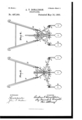
- FIG. 1 is a view in perspective.
- Fig. 2 is a side elevation, one of the side bars being removed.
- Fig. 3 is a vertical cross section, showing the tooth bearing bars expanded, and
- Fig. 4 is a similar view, showing said bars contracted toward the central bar.
- A represents a central bar, carrying any desired teeth or shovels B, engaged therewith in any desired manner.
- a and A represent side bars also carrying teeth or shovels B.
- Thebars A, A and A are united at their forward ends by a yoke C, with which the side bars A A havea jointed connection.
- E E denote the handles firmly engaged at their lower ends with the center bar A, by any suitable means, as by a bolt E.
- This standard is constructed preferably in two upright parts e and e,
- braces H, H lead from the standard to the handles. Additional braces H H are located between the upper end of the standard and the upper portion of the braces H, H, giving much firmness to the construction.
- ' I denotes a lever provided with a pawl G, to engage the rack bar F.
- G is aspring actuating said pawl.
- This lever passes through the elongated slot e ,'and works vertically therein.
- the forward end of this lever is jointedly engaged with a rock bar J, pivotally engaged in the lower ends of the handles, as at a and a, and with an upright arm j, with which the forward end of the lever I is jointedly connected, as indicated at a
- This construction and arrangement obviously, allows the rear end of the lever I to be raised and lowered by disengaging the pawl from the rack bar,'the pawl holding the lever in any desired position.
- K and K denote spread irons, jointedly connected with the lever I at their inner ends, as shown at v1, and with the rear extremities of the bars A A at their outer ends, as shown at In.
- L denote braces jointedly connected at their outer ends with the spread irons, as shown at 1, their inner ends being also jointedly connected at the lower end of the standard, as shown at Z, the standard being provided, for this purpose, with ears f
- What I claim as my invention is- 1.
- a cultivator provided with a center bar, laterally adjustable side bars, and handles, of a rock bar J journaled in said handles, an operating lever I jointedly engaged with said rock bar toward its forward end, an upright standard E braces II and H connecting said standard with said handles, vertically movable spread irons K and K connected with the operating lever and side bars, braces L and L connecting said spread irons to the center bar, and mechanism to hold said lever in given position, substantially as described.
- a cultivator provided with a central tooth bearing bar, adjustable side bars, and handles, an upright standard formed with an elongated slot engaged with the central bar, an operating lever vertically movable in said slot, braces connecting the standard and handles, spread irons jointedly connected with said lever and side bars,braces jointedly connected with the central bar and spreadirons, and mechanism to hold the lever in a given position, substantially as described.
Landscapes
- Life Sciences & Earth Sciences (AREA)
- Engineering & Computer Science (AREA)
- Mechanical Engineering (AREA)
- Soil Sciences (AREA)
- Environmental Sciences (AREA)
- Soil Working Implements (AREA)
Description
(N0 Modl.)
A. DONALDSON.
2 Sheets-Sheet 1.
GULTIVATOR- No. 497,369. Patented May 16, 1 893.
UNrrED STATES PATENT OFFICE;
ANDRE\V T. DONALDSON, OF MOUNT CLEMENS, MICHIGAN.
CU LTlVATO R.
SPECIFICATION forming part of Letters Patent No. 497,369, dated May 16, 1893.
Application filedNovemher 21,1892. Serial No. 452,618. (No model.)
To all whom it may concern:
Be it known that I, ANDREW T. DONALD- SON, a citizen of the United States, residing at Mount Clemens, in the county of Macomb, State of Michigan, have invented certain new and useful Improvements in Cultivators; and I'declare the following to bea full, clear, and exact description of the invention, such as will enable others skilled in the art to which it appertains to make and use the same, reference being had to the accompanying draw ings, which form a part of this specification.
My invention relates to certain new and useful improvements in cul-tivators, and more particularly to an improved lever cultivator, of superior simplicity, efficiency and durability.
The special object of my invention is to provide an implement of this class whereby the side bars of the cultivator may be spread or contracted, as may be desired, and also whereby the handles shall be firmly braced, the operation of the device being easily, quickly and readily accomplished.
To these ends my invention consists of the devices and appliances, their construction, combination and arrangement as hereinafter specified and claimed, and illustrated in the accompanying drawings, in which Figure 1 is a view in perspective. Fig. 2 is a side elevation, one of the side bars being removed. Fig. 3 is a vertical cross section, showing the tooth bearing bars expanded, and Fig. 4 is a similar view, showing said bars contracted toward the central bar.
I carry out my invention as follows:
In the drawings A represents a central bar, carrying any desired teeth or shovels B, engaged therewith in any desired manner. A and A represent side bars also carrying teeth or shovels B. Thebars A, A and A are united at their forward ends by a yoke C, with which the side bars A A havea jointed connection. E E denote the handles firmly engaged at their lower ends with the center bar A, by any suitable means, as by a bolt E. These parts may be constructed in the usual manner.
Toward the rear end of the center bar A is rigidly engaged therewith an upright standard E. This standard is constructed preferably in two upright parts e and e,
united at top and bottom to leave an elongated slot c therebetween. The standard is provided with a rack bar F. Braces H, H lead from the standard to the handles. Additional braces H H are located between the upper end of the standard and the upper portion of the braces H, H, giving much firmness to the construction.
' I denotes a lever provided with a pawl G, to engage the rack bar F. G is aspring actuating said pawl. This lever passes through the elongated slot e ,'and works vertically therein. The forward end of this lever is jointedly engaged with a rock bar J, pivotally engaged in the lower ends of the handles, as at a and a, and with an upright arm j, with which the forward end of the lever I is jointedly connected, as indicated at a This construction and arrangement, obviously, allows the rear end of the lever I to be raised and lowered by disengaging the pawl from the rack bar,'the pawl holding the lever in any desired position.
K and K denote spread irons, jointedly connected with the lever I at their inner ends, as shown at v1, and with the rear extremities of the bars A A at their outer ends, as shown at In. To effect the jointed engagement of may be provided with angle irons or ears i' L, L denote braces jointedly connected at their outer ends with the spread irons, as shown at 1, their inner ends being also jointedly connected at the lower end of the standard, as shown at Z, the standard being provided, for this purpose, with ears f From the above description it will be evident that by manipulating the lever I, the outside bars A and A may be correspondingly spread or contracted as may be desired. The spread irons, in connection with the braces L L between the outside bars, with the standard E together with the upper braces between said standard and the handles, afford greater firmness to the handles, and effectually prevents any shaking or loose motion. It will be observed that the action of the operating lever and its connections with the side bars A and A is in a vertical direction. It will be evident that the lever I has both a vertical and longitudinal movement,
since the rock bar J is rotatably connected the spread irons with the lever I, the latter with the handles. This method of construction does away with a number of pieces or parts required in analogous constructions, and combines spread irons and handle braces in a superior manner, forminga construction of superior simplicity and utility.
What I claim as my invention is- 1. The combination with a cultivator provided with a center bar, laterally adjustable side bars, and handles, of a rock bar J journaled in said handles, an operating lever I jointedly engaged with said rock bar toward its forward end, an upright standard E braces II and H connecting said standard with said handles, vertically movable spread irons K and K connected with the operating lever and side bars, braces L and L connecting said spread irons to the center bar, and mechanism to hold said lever in given position, substantially as described.
2. In a cultivator, the combination with a center bar, adjustable side bars, and handles, of an upright standard, braces leading from said standard to said handles, an operating lever, spread irons leading from said lever to said side bars and having a jointed engagement therewith, braces jointedly connected with said spread irons and said standard, and pawl and ratchet mechanism to hold the operating lever in any given position, substantially as described.
3. In a cultivator provided with a central tooth bearing bar, adjustable side bars, and handles, an upright standard formed with an elongated slot engaged with the central bar, an operating lever vertically movable in said slot, braces connecting the standard and handles, spread irons jointedly connected with said lever and side bars,braces jointedly connected with the central bar and spreadirons, and mechanism to hold the lever in a given position, substantially as described.
4. In a cultivator, the combination with a center bar, laterally adjustable side bars, and handles, of a vertically and longitudinally movable operating lever, a standard provided with a rack bar, vertically operated spread irons connecting the operating lever side bars and cen terbar, apawl engaging said lever and rock bar, and braces connecting the handles with said standard,substantially as described.
In testimony whereof I sign this specification in the presence of two witnesses.
.ANDREVV T. DONALDSON.
\Vitnesses:
N. S. WRIGHT, JOHN F. MILLER.
Publications (1)
| Publication Number | Publication Date |
|---|---|
| US497369A true US497369A (en) | 1893-05-16 |
Family
ID=2566207
Family Applications (1)
| Application Number | Title | Priority Date | Filing Date |
|---|---|---|---|
| US497369D Expired - Lifetime US497369A (en) | Cultivator |
Country Status (1)
| Country | Link |
|---|---|
| US (1) | US497369A (en) |
-
0
- US US497369D patent/US497369A/en not_active Expired - Lifetime
Similar Documents
| Publication | Publication Date | Title |
|---|---|---|
| US799445A (en) | Post-hole digger. | |
| US555059A (en) | Cultivator | |
| US202903A (en) | Improvement in harrows | |
| US137782A (en) | Improvement in cultivators | |
| US516521A (en) | Hand-plow | |
| US756255A (en) | Harrow. | |
| US334641A (en) | Cultivator | |
| US416475A (en) | Harrow | |
| US149181A (en) | Improvement in corn-plows | |
| US1013099A (en) | Self-locking lever. | |
| US508398A (en) | Harrow for listed corn | |
| US226448A (en) | Half of his eight to stewaet d | |
| US495207A (en) | Cultivator | |
| US619382A (en) | Cultivator | |
| US386146A (en) | Cultivator | |
| US510044A (en) | Elijah a | |
| US492307A (en) | Cultivator | |
| US696623A (en) | Cultivator. | |
| US1276531A (en) | Furrowing-machine. | |
| US508995A (en) | Garden-cultivator | |
| US449642A (en) | Cultivator | |
| US816382A (en) | Cultivator. | |
| US476834A (en) | Cultivator | |
| US141462A (en) | Improvep | |
| US303758A (en) | Harrow |