US497339A - Corn-planter - Google Patents
Corn-planter Download PDFInfo
- Publication number
- US497339A US497339A US497339DA US497339A US 497339 A US497339 A US 497339A US 497339D A US497339D A US 497339DA US 497339 A US497339 A US 497339A
- Authority
- US
- United States
- Prior art keywords
- seed
- platform
- axle
- lever
- machine
- Prior art date
- Legal status (The legal status is an assumption and is not a legal conclusion. Google has not performed a legal analysis and makes no representation as to the accuracy of the status listed.)
- Expired - Lifetime
Links
- 240000008042 Zea mays Species 0.000 description 5
- 235000005824 Zea mays ssp. parviglumis Nutrition 0.000 description 4
- 235000002017 Zea mays subsp mays Nutrition 0.000 description 4
- 235000005822 corn Nutrition 0.000 description 4
- 238000010276 construction Methods 0.000 description 3
- 208000028659 discharge Diseases 0.000 description 3
- 241000196324 Embryophyta Species 0.000 description 2
- 239000003550 marker Substances 0.000 description 2
- 241000562516 Thisbe Species 0.000 description 1
- 230000008878 coupling Effects 0.000 description 1
- 238000010168 coupling process Methods 0.000 description 1
- 238000005859 coupling reaction Methods 0.000 description 1
- 230000006870 function Effects 0.000 description 1
- 230000013707 sensory perception of sound Effects 0.000 description 1
- 239000002689 soil Substances 0.000 description 1
Images


Classifications
-
- A—HUMAN NECESSITIES
- A01—AGRICULTURE; FORESTRY; ANIMAL HUSBANDRY; HUNTING; TRAPPING; FISHING
- A01C—PLANTING; SOWING; FERTILISING
- A01C7/00—Sowing
- A01C7/08—Broadcast seeders; Seeders depositing seeds in rows
- A01C7/10—Devices for adjusting the seed-box ; Regulation of machines for depositing quantities at intervals
Definitions
- My invention relates to improvements in corn'planters; the objects in view beingto provide a machine of simple construction and operation, the same being designed to uniformly plant corn in 'hills without the em ployment of check-row wires, their attendant expense, and additional labor.
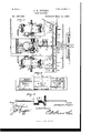
- Figure 1 is a perspective view of a corn-planter embodying my invention.
- Fig. 2 is a plan view thereof.
- Fig. 3 is a longitudinal sectional view taken centrally through the machine.
- Fig. 4 is a plan view of the hoppers, the seed-disk and cut-0E removed.
- Fig. 5 is a detail of the axle.
- Fig. 6 is a vertical longitudinal section through one of the hoppers and seed-spout or tube.
- Fig.7 is a detail in side elevation of the lever and locking pawl for operating the axle.
- Clutch-sleeves 6 having teeth are splined upon the axle and may be thrown into en gagement either singly or simultaneously with the teeth of the hubs through the medium of a pair of levers 7, that are fulcrumed in brackets 8 with which each'of the side bars are provided.
- Each lever has pivoted in a are out of engagement with the hubs of the wheels, so that the latter are free to revolve independent of the axle, but when the pawls are engaged with the inner notches the lower ends of the levers have been swung outward and the clutch-sleeves engaging the toothed hubs of the wheels, the axle and wheels will therefore move together, and when this is accomplished the motion, as hereinafter described, will be imparted to the feeding mechanism of the machine.
- a transverse bar 11 connects the side-bars 1 intermediate their ends, and a central bar 12 connects the intermediate bar 11 with the cross-bar 2 at therear end'of the frame.
- the seat standard 13 Upon this bar 12 there is supported the seat standard 13, the seat 14: 'surmounting the standard and thus accommodating the driver who is seated between the two levers at the opposite sides of the machine, whereby he may readily operate the same.
- Bearings 15 are located at opposite sides of a slot in the longitudinal bar 12, and in these hearings a short cranked rock-shaft 16 is journaled, one end of which is extended upward beyond the bearings to form an operating lever or arm 17.
- a platform 27 Surmounting the sidebars 1 near their front ends is a platform 27, and secured to the same at its front edge is a transverse yoke 28 which supports a bowed runner or track 29.
- a ring 30 is loosely mounted on the runner and adapted to travel from one end to the other thereof, and to this ring is connected the cord or chain the rear end being secured to a markingbar 31 carrying a marker 32 and pivoted at its inner end to the center of the rear cross bar 2 of the framework.
- This marking bar may be swung to either side of the machine and in so doing the ring will travel over the runner to the opposite end and the chain or rope connecting the ring with the marking bar and by which the markingbar is swung will be carried up over the mechanism of the machine and over the head of the driver or operator.
- a rockshaft 34 is journaled, the ends of which extend beyond the platform.
- the rear or inner end of the rock-shaft is bent to form a crank handle 36 and the outer or forward end a long crank arm 37.
- a block 38 connects the two ends of the side-bars 1 in advance of the plat form, and to the same is pivoted as at 39 an arm 40, which at its outer end is provided with a rearwardly-extending rod 41 carrying a dou ble-ended marker +12.
- the arm is provided with a longitudinal slot 43, and in the same loosely rides the extremity of the crank-arm 37. It will thus be seen that the driver while perched upon his seat may by operating the crank-handle swing the arm 40 to either side of the machine.
- the seed-platform 44 is located under the front ends of the side-bars 1 in advance of the wheels and is provided upon its upper side at each side of its center with convexed bolster-blocks 45 whose lower edges are recessed or provided with openings 46 and whose upper convexed portions are loosely connected by couplings 47 with the lower edges of the side-bars 1.
- a draft-tongue 48 is secured to the seed-platform and carries the usual double and single trees.
- Seed hoppers 4E9 surmount the seed-platform at the outer sides of the sidebars 1 and have openings in their side walls which agree with the openings in the bolsters.
- a transversely -reeiprocating seed bar 53 surmounts the seed-platform and is mounted in the openings in the bolster and walls of the hoppers, and said seed-bar is provided near its ends with openings 5t which align with the central openings in the hopper bottoms.
- the seed bar has loosely pivoted thereto gravity-pawls 54, Whose free ends ride loosely over the corn platform and alternately engage the radial arms of a star-shaped plate 55, one of which is located upon the seed-platform below the central opening of each of the hopper bottoms, and each plate is provided with a plurality of upwardly-disposed pins 56.
- Circular seed-disks 57 surmount the bottoms of the hoppers and are provided with openings 58 through which the pins of the plates take.
- Each seed plate is further provided with an annular series of perforations 59, which are designed to be successively brought into register with the discharge openings in the bottoms of the hoppers.
- the axle is provided with a grooved cam 63, and moving in the track of the cam is a loose anti-friction roller 64, which is carried by the rear end of a vibratory lever 65 that is fulcrumed on the under side of the intermediate cross-barll, and has its front end slotted at 66 and loosely connected or engaged with a stud 67 that extends upward from the seed-bar, whereby as the axle rotates the cam serves to oscillate or vibrate the lever and it in turn reciprocates in a transverse manner the seed-bar, thus feeding through the instrumentality of the ratchet or star-shaped disks the seed disks of the hoppers.
- the axle is provided with a cog-wheel 68, and at one side of the cog-wheel, which is fast upon the axle, there is loosely connected or journaled a vibrating-lever 69, which has pi voted thereto a pawl-lever 70, the lower end of which is designed to engage with the teeth of the cogwheel, but is normally maintained out of such engagement by means of a spring 71 interposed between it and the aforesaid lever.
- a rock-shaft 72 is rigidly secured thereto is a lever 73 that extends upwardthrough an opening 74 formed inplatform 27.
- This lever is provided with a look ing pawl 75 spring-pressed by a spring 76 so that its lower end will engage with either one of a pair of notches 77 formed in the edge of the opening in the platform.
- arms 78 extend from the rock-shaft and the same are connected loosely by means of links 79 with the rear extremities of the hounds 80 which are secured rigidly to the underside of the seed-platform and project a slight dis tance in rear thereof.
- the lever at the side of the driver is oscillated so as to bring the plain or unheaded arms of the rotatable indicators opposite the indicating-arms or pointers thatproject from the side bars after which the levers at the sides of the frame are swung inward and locked, thus locking the ground-wheels and axle together.
- the rock-shaft is then operated by its lever in the manner described, so as to lower the runners into the ground or into operative position, and the marking-bars swung to the proper side of the machine.
- the machine is then started and the first row planted.
- the parts are so provided in the present instance that two corn-hills will be formed with every one revolution of the ground-wheels, and at points opposite the corn-hills the headed indicating arms will make an impression in the soil so as to indicate the points of planting. Then the machine has reached the end of the row or field and it is desired to turn the same, the levers at the sides of the machine are swung outward so as to disengage the clutches with the wheels, and thus the machine may swing around without operating the planting mechanism.
- the marker-bar or arm When swung around to travel in the reverse direction from which it started, or to form the second row, the marker-bar or arm is reversed and the driver ascertains that the tongue or draft-pole is in direct alignment with the previously made mark; next he ascertains if the indicator at the front of the machine is directly over the first hill of the row. If thisbe not so, then it is necessary to move the machine until it is. Such movement may be accurately accomplished by means of the lever at the side of the driver; after which he adjusts his rotatable hillmarkers so that the plain arms thereof are directly under the indicating wire or rod extending from the side of the machine.
- the machine is comparatively simple in its mechanism, comprising few parts, is adapted to uniformly plant, and is under complete and convenient control of a single operator.
- the seed-chute 60 is'provided with the usual flirt-valve the same performing its usual function, and being provided at its upper end with the bent or L- shaped arm 60 which is engaged and oscillated by two pins 60 which depend from the slide 53.
- the combination with the rectangular platform comprising the opposite side bars, the axle and the groundrwheels for supporting the same, of a seed platform '10- cated below the side bars opposite, convexed' 10o bolsters surmounting the platform and loosely coupled with the side bars of the framework, planting mechanism carried by the platform, and means for inclining the front or rear edge of the platform, substantially as specified.
Landscapes
- Life Sciences & Earth Sciences (AREA)
- Soil Sciences (AREA)
- Environmental Sciences (AREA)
- Sowing (AREA)
Description
(No Model.) a Sheets-Sheet 1.
J. H. PETERS.
CORN PLANTER.
No. 497,339. Patented May 16, 1893.
Iryhgiir, Jami P636715,
13y mu firgzys,
(No Model.) a Sheets-Sheet 2.
' J. H. PETERS.
- CORN PLANIER.
No. 497,339. Patented May 16, 1893.
m: poems PETERS co. womuma. WASNINETON. m c.
(No Model.) s Sheets-Sheet a,
J. HQPBTBRS.
CORN PLANTBR. No. 497,339. Patented May 16, 1893.
mmmmmnnnm E E alqfim'geys,
THE NQRR'S PETERS C01, PHmQ-LlTFiO WAsHINGTON. Dv C. I
UNITED STATES PATENT OFFICE.
JAMES HARDEN PETERS, on sTow Rs, KENTUCKY.
CORN-PLANTER.
SPECIFICATION forming part of Letters Patent N' o. 497,339, dated May 16, 1893. Application filed December 5, 1892., Serial No.4:54,160. (N0 model.)
To (1 whom it may concern:
Be it known that 1, JAMES HARDEN PETERS, a citizen of the United States, residing at Stowers, in the county of Simpson and State of Kentucky, have invented a new and useful Corn-Planter, of which the following is a specification.
My invention relates to improvements in corn'planters; the objects in view beingto provide a machine of simple construction and operation, the same being designed to uniformly plant corn in 'hills without the em ployment of check-row wires, their attendant expense, and additional labor.
With the above as the main objects of my inventiomthe same consists in certain features of construction and combinations of parts hereinafter specified and particularly pointed out in the claims.
Referring to the drawings:Figure 1 is a perspective view of a corn-planter embodying my invention. Fig. 2 is a plan view thereof.
Fig. 3 is a longitudinal sectional view taken centrally through the machine. Fig. 4 is a plan view of the hoppers, the seed-disk and cut-0E removed. Fig. 5 is a detail of the axle. Fig. 6 is a vertical longitudinal section through one of the hoppers and seed-spout or tube. Fig.7 is a detail in side elevation of the lever and locking pawl for operating the axle.
Like numerals of reference indicate like parts in all the figures of the drawings.
In practicing my invention I employ opposite side bars 1, which are widened toward their centers and are connected at their rear ends by a transverse bar 2. At their widest portions, or in other words, at the centers or, the side bars, the same are provided with journaled bearings, and mounted loosely for rotation in said bearings is the'axle 3. The axle 3 extends beyond its bearings, and carries ground-wheels 4, which preferably are provided with concaved tires. The hubs or inner faces of the ground wheels are provided with teeth 5 and are loosely mounted on the axle. Clutch-sleeves 6 having teeth are splined upon the axle and may be thrown into en gagement either singly or simultaneously with the teeth of the hubs through the medium of a pair of levers 7, that are fulcrumed in brackets 8 with which each'of the side bars are provided. Each lever has pivoted in a are out of engagement with the hubs of the wheels, so that the latter are free to revolve independent of the axle, but when the pawls are engaged with the inner notches the lower ends of the levers have been swung outward and the clutch-sleeves engaging the toothed hubs of the wheels, the axle and wheels will therefore move together, and when this is accomplished the motion, as hereinafter described, will be imparted to the feeding mechanism of the machine. I
A transverse bar 11 connects the side-bars 1 intermediate their ends, and a central bar 12 connects the intermediate bar 11 with the cross-bar 2 at therear end'of the frame. Upon this bar 12 there is supported the seat standard 13, the seat 14: 'surmounting the standard and thus accommodating the driver who is seated between the two levers at the opposite sides of the machine, whereby he may readily operate the same. Bearings 15 are located at opposite sides of a slot in the longitudinal bar 12, and in these hearings a short cranked rock-shaft 16 is journaled, one end of which is extended upward beyond the bearings to form an operating lever or arm 17. I In bearings 18 located uponthe under sides of the bars 1 near their rear ends a rock-shaft 19 is journaled, and the same at its ,ends carries convexed scraping-blades 20. The center of this rock-shaft is provided with a cranked portion 21, and the same is'bya link 22 connected loosely with the central cranked portion of the rock-shaft 16. It will thus be seen that the driver by manipulating the lever 17 Ice bars 1 immediately above the axle, and the same are used in conjunction with the markers just described in a manner that will here inafter be made apparent.
Surmounting the sidebars 1 near their front ends is a platform 27, and secured to the same at its front edge is a transverse yoke 28 which supports a bowed runner or track 29. A ring 30 is loosely mounted on the runner and adapted to travel from one end to the other thereof, and to this ring is connected the cord or chain the rear end being secured to a markingbar 31 carrying a marker 32 and pivoted at its inner end to the center of the rear cross bar 2 of the framework. This marking bar may be swung to either side of the machine and in so doing the ring will travel over the runner to the opposite end and the chain or rope connecting the ring with the marking bar and by which the markingbar is swung will be carried up over the mechanism of the machine and over the head of the driver or operator.
In bearings 33 located longitudinallyropposite each other upon the platform 27 a rockshaft 34 is journaled, the ends of which extend beyond the platform. The rear or inner end of the rock-shaft is bent to form a crank handle 36 and the outer or forward end a long crank arm 37. A block 38 connects the two ends of the side-bars 1 in advance of the plat form, and to the same is pivoted as at 39 an arm 40, which at its outer end is provided with a rearwardly-extending rod 41 carrying a dou ble-ended marker +12. The arm is provided with a longitudinal slot 43, and in the same loosely rides the extremity of the crank-arm 37. It will thus be seen that the driver while perched upon his seat may by operating the crank-handle swing the arm 40 to either side of the machine.
The seed-platform 44: is located under the front ends of the side-bars 1 in advance of the wheels and is provided upon its upper side at each side of its center with convexed bolster-blocks 45 whose lower edges are recessed or provided with openings 46 and whose upper convexed portions are loosely connected by couplings 47 with the lower edges of the side-bars 1. A draft-tongue 48 is secured to the seed-platform and carries the usual double and single trees. Seed hoppers 4E9 surmount the seed-platform at the outer sides of the sidebars 1 and have openings in their side walls which agree with the openings in the bolsters. Above these openings in the hoppers the bottoms 50 thereof are located, and the bottoms are provided with central circular openings 51 and in rear of the same with discharge openings 52. A transversely -reeiprocating seed bar 53 surmounts the seed-platform and is mounted in the openings in the bolster and walls of the hoppers, and said seed-bar is provided near its ends with openings 5t which align with the central openings in the hopper bottoms. At diagonally opposite corners of its openings the seed bar has loosely pivoted thereto gravity-pawls 54, Whose free ends ride loosely over the corn platform and alternately engage the radial arms of a star-shaped plate 55, one of which is located upon the seed-platform below the central opening of each of the hopper bottoms, and each plate is provided with a plurality of upwardly-disposed pins 56. Circular seed-disks 57 surmount the bottoms of the hoppers and are provided with openings 58 through which the pins of the plates take. Each seed plate is further provided with an annular series of perforations 59, which are designed to be successively brought into register with the discharge openings in the bottoms of the hoppers. From the dis charge openings in the bottoms of the hoppers and platforms which are but continuations of those in the hoppers, depend the usual seedtubes 60, which arelocated in the runners 01, the forward ends of said runners being so cured to a transverse bar 62 which is supported by the draft-tongue and is therefore rigid with the seed-platform.
Between its bearings the axle is provided with a grooved cam 63, and moving in the track of the cam is a loose anti-friction roller 64, which is carried by the rear end of a vibratory lever 65 that is fulcrumed on the under side of the intermediate cross-barll, and has its front end slotted at 66 and loosely connected or engaged with a stud 67 that extends upward from the seed-bar, whereby as the axle rotates the cam serves to oscillate or vibrate the lever and it in turn reciprocates in a transverse manner the seed-bar, thus feeding through the instrumentality of the ratchet or star-shaped disks the seed disks of the hoppers. At one side of the cam the axle is provided with a cog-wheel 68, and at one side of the cog-wheel, which is fast upon the axle, there is loosely connected or journaled a vibrating-lever 69, which has pi voted thereto a pawl-lever 70, the lower end of which is designed to engage with the teeth of the cogwheel, but is normally maintained out of such engagement by means of a spring 71 interposed between it and the aforesaid lever. .Tournaled in the side bars 1 below the platform 27 is a rock-shaft 72, and rigidly secured thereto is a lever 73 that extends upwardthrough an opening 74 formed inplatform 27. This lever is provided with a look ing pawl 75 spring-pressed by a spring 76 so that its lower end will engage with either one of a pair of notches 77 formed in the edge of the opening in the platform. arms 78 extend from the rock-shaft and the same are connected loosely by means of links 79 with the rear extremities of the hounds 80 which are secured rigidly to the underside of the seed-platform and project a slight dis tance in rear thereof. This completes the construction of the machine, and it will be seen that by a manipulation of those levers at the sides of the frame either one or both of the wheels maybe made rigid with the axle or independent thereof; furthermore that IIO Short rocki when said wheels are loose orindependent of the axle, the axle will be rotated through the medium of the lever and lever-pawl atthe side of the driver and the cog-wheel of the axle so that the indicating-arms carried by the axle may be rotated or brought to a proper point for a purpose hereinafter apparent; and finally it will be seen that by a manipulation of a lever controlling the rockshaft the runners may be set into the ground so as to form a furrow for planting the seed, or withdrawn from such lowered position. Such movement upon the parts of the runners is permitted by reason of the loose connection between the framework and the seedplatform, which has been previously described.
To operate the machine the lever at the side of the driver is oscillated so as to bring the plain or unheaded arms of the rotatable indicators opposite the indicating-arms or pointers thatproject from the side bars after which the levers at the sides of the frame are swung inward and locked, thus locking the ground-wheels and axle together. The rock-shaft is then operated by its lever in the manner described, so as to lower the runners into the ground or into operative position, and the marking-bars swung to the proper side of the machine. The machine is then started and the first row planted. The parts are so provided in the present instance that two corn-hills will be formed with every one revolution of the ground-wheels, and at points opposite the corn-hills the headed indicating arms will make an impression in the soil so as to indicate the points of planting. Then the machine has reached the end of the row or field and it is desired to turn the same, the levers at the sides of the machine are swung outward so as to disengage the clutches with the wheels, and thus the machine may swing around without operating the planting mechanism. When swung around to travel in the reverse direction from which it started, or to form the second row, the marker-bar or arm is reversed and the driver ascertains that the tongue or draft-pole is in direct alignment with the previously made mark; next he ascertains if the indicator at the front of the machine is directly over the first hill of the row. If thisbe not so, then it is necessary to move the machine until it is. Such movement may be accurately accomplished by means of the lever at the side of the driver; after which he adjusts his rotatable hillmarkers so that the plain arms thereof are directly under the indicating wire or rod extending from the side of the machine. He is now read yto plant the second row, and at the end of this row the operation is repeated, so that when the field has been'planted the rows are absolutely uniform. Should the machine come to an obstruction around which it is necessary to drive, the parts may be thrown out of operative position, as will be obvious, V and when the opposite side of the obstruction is reached, the machine may be started in the same manner as when at the beginning of a row.
It will be seen that the machine is comparatively simple in its mechanism, comprising few parts, is adapted to uniformly plant, and is under complete and convenient control of a single operator. It will of course be understood that the seed-chute 60, is'provided with the usual flirt-valve the same performing its usual function, and being provided at its upper end with the bent or L- shaped arm 60 which is engaged and oscillated by two pins 60 which depend from the slide 53.
Having described my invention, what I claim is 1. In a planter, the combination with the rectangular frame provided upon its upper side with longitudinally-opposite bearings, of a-rock-shaft mounted in the bearings and terminating at its front and rear ends in crankarms, a lever or arm pivoted at its inner end to the frame-work and longitudinally-slotted to engage the outer crank arm, and an indicator terminating transversely opposite the planting mechanism and carried by said arm, substantially as specified.
2. In a planter, the combination with the rectangular platform comprising the opposite side bars, the axle and the groundrwheels for supporting the same, of a seed platform '10- cated below the side bars opposite, convexed' 10o bolsters surmounting the platform and loosely coupled with the side bars of the framework, planting mechanism carried by the platform, and means for inclining the front or rear edge of the platform, substantially as specified.
3. In a planter, the combination with the rectangular platform, the axle and ground wheels, of a seed-platform carrying the planting mechanism, convexed bolsters surmounting the seed-platform and loosely coupled [to with and supporting the side bars of the framework, hounds secured to the under side of the seed-platform and extending inrear thereof, a rock-shaft journaled in the side bars of the frame, rock-arms extending from the x15 shaft, links loosely connecting the ends of the rock-arms with the rear ends of the bounds, a superimposed platform having an opening provided with locking notches at one side thereof, and a lever extending from the rockshaft through the opening and provided with a pawl for engagingthe notches, substantially as specified.
In testimony that I claim the foregoing as my own I have hereto affixed my signature in 12 5 the presence of two witnesses.
V JAMES I-IARDEN PETERS. Witnesses:
GEo. CLHARRIS,
C. B. MOORE.
Publications (1)
| Publication Number | Publication Date |
|---|---|
| US497339A true US497339A (en) | 1893-05-16 |
Family
ID=2566177
Family Applications (1)
| Application Number | Title | Priority Date | Filing Date |
|---|---|---|---|
| US497339D Expired - Lifetime US497339A (en) | Corn-planter |
Country Status (1)
| Country | Link |
|---|---|
| US (1) | US497339A (en) |
Cited By (2)
| Publication number | Priority date | Publication date | Assignee | Title |
|---|---|---|---|---|
| US5027525A (en) * | 1989-10-02 | 1991-07-02 | Duane Haukaas | Field marker |
| US5425427A (en) * | 1994-01-13 | 1995-06-20 | Poma Industries, Inc. | Folding marker for agricultural implement |
-
0
- US US497339D patent/US497339A/en not_active Expired - Lifetime
Cited By (2)
| Publication number | Priority date | Publication date | Assignee | Title |
|---|---|---|---|---|
| US5027525A (en) * | 1989-10-02 | 1991-07-02 | Duane Haukaas | Field marker |
| US5425427A (en) * | 1994-01-13 | 1995-06-20 | Poma Industries, Inc. | Folding marker for agricultural implement |
Similar Documents
| Publication | Publication Date | Title |
|---|---|---|
| US242063A (en) | Signoe op one-half to william e | |
| US225426A (en) | Marking and dropping attachment for planters | |
| US941874A (en) | Corn-planter. | |
| US352315A (en) | Combined drill and planter | |
| US148246A (en) | Improvement in corn-planters | |
| US328160A (en) | Combined check-rower and self-dropping corn-planter | |
| US212469A (en) | Improvement in check-row planter and drill | |
| US174179A (en) | Improvement in corn-planters | |
| US176244A (en) | Improvement in check-row planters | |
| US819409A (en) | Corn-planter. | |
| US444030A (en) | Corn-planter | |
| US304825A (en) | Self-dropping corn-planter | |
| US371051A (en) | Corn-planter | |
| US500909A (en) | Corn-planter | |
| US290670A (en) | dillee | |
| US393531A (en) | Row-checking corn-planter | |
| US929971A (en) | Planter. | |
| USRE8547E (en) | Improvement in corn-planters | |
| US227822A (en) | Corn-planter | |
| US202196A (en) | Improvement in corn-planter attachments | |
| US420280A (en) | Check-row planter | |
| US159210A (en) | Improvement in seeding-machines | |
| US559825A (en) | Check-row corn-planter | |
| US339124A (en) | Corn-planter | |
| US425364A (en) | berrien |