US4970547A - System and method for generating and codifying photo cropping and enlargement information - Google Patents
System and method for generating and codifying photo cropping and enlargement information Download PDFInfo
- Publication number
- US4970547A US4970547A US07/482,192 US48219290A US4970547A US 4970547 A US4970547 A US 4970547A US 48219290 A US48219290 A US 48219290A US 4970547 A US4970547 A US 4970547A
- Authority
- US
- United States
- Prior art keywords
- photo
- overlay
- board
- grid
- window
- Prior art date
- Legal status (The legal status is an assumption and is not a legal conclusion. Google has not performed a legal analysis and makes no representation as to the accuracy of the status listed.)
- Expired - Fee Related
Links
Images


Classifications
-
- G—PHYSICS
- G03—PHOTOGRAPHY; CINEMATOGRAPHY; ANALOGOUS TECHNIQUES USING WAVES OTHER THAN OPTICAL WAVES; ELECTROGRAPHY; HOLOGRAPHY
- G03B—APPARATUS OR ARRANGEMENTS FOR TAKING PHOTOGRAPHS OR FOR PROJECTING OR VIEWING THEM; APPARATUS OR ARRANGEMENTS EMPLOYING ANALOGOUS TECHNIQUES USING WAVES OTHER THAN OPTICAL WAVES; ACCESSORIES THEREFOR
- G03B27/00—Photographic printing apparatus
- G03B27/32—Projection printing apparatus, e.g. enlarger, copying camera
- G03B27/52—Details
- G03B27/62—Holders for the original
- G03B27/6207—Holders for the original in copying cameras
- G03B27/6242—Masks; Overlays; Transparent carriers
-
- G—PHYSICS
- G03—PHOTOGRAPHY; CINEMATOGRAPHY; ANALOGOUS TECHNIQUES USING WAVES OTHER THAN OPTICAL WAVES; ELECTROGRAPHY; HOLOGRAPHY
- G03B—APPARATUS OR ARRANGEMENTS FOR TAKING PHOTOGRAPHS OR FOR PROJECTING OR VIEWING THEM; APPARATUS OR ARRANGEMENTS EMPLOYING ANALOGOUS TECHNIQUES USING WAVES OTHER THAN OPTICAL WAVES; ACCESSORIES THEREFOR
- G03B27/00—Photographic printing apparatus
- G03B27/32—Projection printing apparatus, e.g. enlarger, copying camera
- G03B27/52—Details
- G03B27/62—Holders for the original
- G03B27/6271—Holders for the original in enlargers
Definitions
- This invention relates generally to photography accessories and more particularly to a system and method for generating and codifying cropping and enlargement information for a photograph.
- the individual For an individual to obtain an enlargement of a selected area of a photograph, the individual commonly takes his photograph to a photo shop where the necessary cropping information is generated and recorded. Normally, much detailed information regarding the photo area to be cropped and enlarged is accumulated and recorded in order that the area to be enlarged may be accurately isolated at a later time. In some instances, the photograph is marked upon to indicate the area to be cropped. The recorded information is subsequently sent, along with the photograph, to a photo laboratory where the preselected area of the photograph is enlarged.
- Another object of the present invention is to provide such a system which is particularly well-suited for the communication of photo cropping and enlargement information to a recipient who is responsible for the enlargement of a selected area of the photo.
- Still another object of the present invention is to provide such a system which enables an individual to readily isolate an area of a photo for cropping purposes and which does not require that the photo be marked upon.
- Yet another object of the present invention is to provide such a system which is economical to construct and uncomplicated to use.
- This invention resides in a system and method for generating and codifying cropping and enlargement information for a rectangular photo and transfer of such information to a remote location for use in the reproduction of such photo.
- the system includes at least one transparent overlay and a grid board for underlying the overlay.
- the overlay includes means defining a plurality of concentric rectangular windows arranged about a common center and identification indicia associated with each rectanglar window. Each window is sized to correspond to a fraction of a predetermined photo size so that by enlarging the size of the window by a preselected multiple, the window size is equal to the predetermined photo size.
- each rectangular window is arranged so that two of its opposite sides are generally parallel to two sides of the other rectangular windows of the overlay so that by placing the overlay over a photo and viewing an area of the photo through the plurality of windows as the photo area is substantially centered beneath the common center of the windows, the viewer may readily select one of the rectangular windows as the one window which most suitably frames the photo area.
- the grid board of the system has a flat surface and means defining a pair of intersecting lines viewable on the flat surface and which are disposed at a right angle to one another and which intersect so as to divide the flat surface into four quadrants.
- the board also includes means defining a pattern of markings associated with the intersecting lines which provide one of the four quadrants with a two-coordinate grid wherein each of the two coordinate axes of the grid is parallel to a corresponding one of the intersecting lines and indicia for identifying coordinate locations on the grid.
- the transparent overlay is positionable over the flat surface of the board so that when the overlay is arranged in overlying relationship with the board surface so that the common center of the rectangular windows overlies the intersection of the intersecting lines of the grid board and each side of each rectangular window is parallel to one of the two coordinate axes of the grid, one corner of each rectangular window overlies the grid of the grid board.
- the transparent overlay and a rectangular photo having an area desired to be enlarged are positioned upon the board surface so that the photo is positioned between the overlay and the board surface and so that the common center of the rectangular windows of the overlay overlies the intersection of the intersecting lines of the grid board and each side of each rectangular window is parallel to one of the two coordinate axes of the grid. While maintaining each edge of the photo in a parallel relationship with a corresponding one of the two coordinate axes of the grid and maintaining the positional relationship between the overlay and the board surface, the photo is manipulated between positions beneath the transparent overlay until the photo area desired to be enlarged is suitably framed by one of the rectangular windows of the overlay.
- the identity of the one rectangular window of the transparent overlay chosen as suitably framing the photo area is noted and the location on the grid overlain by a corner of the photo is also noted.
- the photo area desired to be enlarged can be accurately isolated with the system at a later time.
- FIG. 1 is a perspective view of an embodiment of a system used to obtain cropping and enlargement information for a rectangular photograph.
- FIG. 2 is a plan view of the front face of the transparent overlay of the FIG. 1 system.
- FIGS. 3-5 are views similar to that of FIG. 2 illustrating the front faces of extra overlays of the FIG. 2 system, but drawn to a smaller scale.
- FIG. 6 is a plan view of the flat surface of the grid board of the FIG. 1 system.
- FIG. 7 is a cross-sectional view taken about on line 7--7 of FIG. 6.
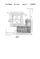
- FIG. 8 is a view of the FIG. 1 system being used to select an area of a photograph to be enlarged.
- FIG. 9 is a view of a fragment of the FIG. 1 system and a photograph wherein the photograph has been positioned in a desired location beneath the transparent overlay of the system.
- FIG. 1 an embodiment of a system 20 used for generating and codifying cropping and enlargement information relating to a rectangular photograph 22.
- the photograph 22 is a snapshot which has an area which is desired to be enlarged to a predetermined size.
- the system 20 enables a selected area of the photo 20 to be readily chosen and information regarding the chosen area, such as its precise location on the photo, to be codified so that the chosen area of the photo may be accurately isolated at a later time for enlargement to a desired size.
- the system 20 includes a grid board 24 and a series of transparent overlays 30, 32, 34 and 36 for use with the board 24.
- Each transparent overlay 30, 32, 34 or 36 corresponds to a predetermined photograph size to which an area of the photo 22 may be enlarged and in the illustrated system 20, corresponds to a standard rectangular photo size.
- the overlay 30 corresponds to a preselected photo size having rectangular edges which measure 5.0 inches by 7.0 inches; the overlay 32 corresponds to a preselected photo size having rectangular edges which measure 8.0 inches by 10.0 inches; the overlay 34 corresponds to a preselected photo size having rectangular edges which measure 11.0 inches by 14.0 inches; and the overlay 36 corresponds to a preselected photo size having rectangular edges which measure 16.0 inches by 20.0 inches.
- the system 20 is used by first selecting the size of the photograph to which an area of the photo 22 is desired to be enlarged. Once the photograph size is selected, the transparent overlay which corresponds to that photograph size is used with the grid board 24.
- a system embodiment in accordance with the broader aspects of this invention may include only one transparent overlay, but the advantage provided by the series of overlays 30, 32, 34 or 36 relates to the plurality of choices: of enlargement sizes from which the user of the system may select.
- Each overlay 30, 32, 34 or 36 is constructed of a flexible, yet durable sheet of plastic material which is relatively square in shape. In the depicted system 20, the edges of each overlay are about 14.0 inches long.
- each overlay 30, 32, 34 or 36 includes a pair of apertures 38 disposed adjacent the top edge of the overlay for a purpose apparent herein. In the embodiment 20, each aperture 38 is somewhat oval in shape.
- each overlay 30, 32, 34 or 36 includes means defining two intersecting lines 40, 42 disposed at a right angle with respect to one another and which intersect at a point 44 which corresponds generally to the center of the overlay.
- the intersecting lines 40, 42 are printed on one side of the overlay sheet so as to be visible through the front surface of the overlay sheet.
- Each overlay 30, 32, 34 or 36 also includes means defining a plurality of concentrically-arranged rectangular windows 46 having a common center which coincides with the intersection 44 of the lines 40, 42.
- the side of each window 46 is provided by lines which are printed on one side of the overlay sheet and which are joined together at the window corners to form the rectangular boundary around the window 46.
- each overlay 30, 32, 34 or 36 includes at least five rectangular windows 46.
- Each overlay 30, 32, 34 or 36 also includes identifying indicia 48 for separately identifying each window 46.
- the indicia 48 includes a numeral associated with each window 46 wherein the numeral designates the percentage multiple to which the rectangular window must be enlarged to enlarge the size of the window to the photo size to which the overlay corresponds.
- the numerals printed upon the overlay 30 range from 100 to 500 wherein the rectangular window 46 identified by the numeral designation 100 has edge dimensions which measure 5.0 inches by 7.0 inches, i.e., the actual photo size to which the overlay 30 corresponds.
- the size of the rectangular window 46 designated by the numeral 500 must be enlarged by five hundred percent to render the edge dimensions of this window equal to 5.0 inches by 7.0 inches.
- the grid board 24 includes a rigid, generally square platen 50 having a smooth, flat front surface 52 and a flat rear surface 54.
- indicia 56 including a pair of intersecting lines 58, 60 disposed at a right angle with respect to one another and which intersect at point 62 located at about the center of the platen surface 52.
- One line 58 is parallel to the top and bottom edges of the platen 50, and the other line 60 is parallel to the side edges of the platen 50 so that the lines 58, 60 mark off the front surface 52 of the platen 50 into four quadrants.
- the grid board indicia 56 also includes a pattern of intersecting lines 64 which provide one of the four quadrants with a two-coordinate grid 66 wherein one coordinate of the grid 66 is parallel to one intersecting line 58 and the other coordinate of the grid 66 is parallel to the other intersecting line 60.
- the grid 66 markings 68 enabling an individual to identify any coordinate location on the grid 66 with two coordinate information.
- the grid locations are identified by a series of letters and numerals extending along the left and bottom edges, as shown in FIGS. 6 and 9, of the grid 66.
- Also outlined in dotted lines upon the board surface 52 are printed outlines 70, in actual size, of the edges of preselected photos wherein each photo is centered about the intersection 62 of the lines 58, 60.
- the platen 50 of the board 24 is comprised of a rigid layer of transparent plastic, and the indicia 56 is printed upon an opaque plastic sheet 72 which is laminated to the rear surface 54 of the platen 50 so that the indicia 56 printed upon the sheet 72 are visible through the front surface 52 of the platen 50.
- each edge of the platen 50 is about 15.0 inches long.
- the board 24 also includes a bracket 74 which is glued or otherwise affixed to the platen 50 adjacent its top edge for securing an overlay in position upon the platen surface 52.
- the bracket 74 has two cylindrically-bodied posts, or lugs 76, which extend generally away from the platen surface 52 and which ar sized to snugly accept the apertures 38 of an overlay placed upon the surface 52. Therefore, when an overlay is placed in overlying relationship with the platen surface 52 and the overlay apertures 38 are snugly received by the bracket lugs 76, one edge, i.e. the top edge, of the overlay and platen 50 cooperate to releasably secure the overlay in position over the platen surface 52. For a reason apparent herein, the lower edge of the overlay is free to be lifted from the platen surface 52 in the manner illustrated in FIG. 8.
- an individual must first select the size to which an area of the photo 22 is desired to be enlarged. It will be assumed for exemplary purposes that an area of the photo 22 is desired to be enlarged to a standard photo size having edges which measure 5.0 inches by 7.0 inches. Accordingly and with reference again to FIG. 1, the transparent overlay 30 which corresponds to the 5.0 inch by 7.0 inch photo size is placed in overlying relationship with the grid board 24 with its apertures 38 snugly positioned about the lugs 76 of the board bracket 74. The photo 22 is then positioned face-up between the overlay 30 and platen surface 52 by lifting one corner of the overlay 30, as viewed in FIG. 1, and sliding the photo 22 edgewise between the overlay 30 and the platen surface 52 so that the photo is viewed in the correct orientation through the overlay 30.
- the photo 22 is shifted between positions upon the platen surface 52 until the user centers the area of the photo 22 desired to be enlarged beneath the common center 44 of the rectangular windows 46 of the overlay 30. It will be understood that during this manipulation step, each edge of the photo 22 is maintained in a parallel relationship with a corresponding one of the coordinates of the grid 66 and the cooperation between the bracket lugs 76 and overlay apertures 38 maintain the positional relationship between the overlay 30 and board surface 52. The user then replaces the lower edge of the overlay upon the board surface 32 and chooses one of the rectangular windows 46 which best frames the photo area to his satisfaction.
- a record is made of the indicia numeral corresponding to the chosen window 46.
- the user records the percentage multiple by which the size of the chosen window 46 must be increased to enlarge the area of the chosen window to a 5.0 inch by 7.0 inch photo size, as well as the identity of the chosen window 46.
- one corner i.e., the lower, righthand corner, of the photo 22 overlies the grid 66 of the board 24 as best shown in FIG. 9.
- a notation is made of the grid location overlain by the corner of the photo 22.
- the grid location overlain by the photo corner is indicated 80 in FIG. 8 and can be identified, of course, by the numerals and letters bordering the left and bottom edges of the grid 66 for identifying in a conventional manner any location on the grid 66 crossed by the grid lines 64.
- an individual places the photo 22 correct-side-up on the board surface 52 so that the lower, right hand corner of the photo 22 is positioned over the location 80 of the grid 66 corresponding to the coordinate information noted to designate the coordinate location on the grid 66 previously overlain by the lower, right hand corner of the photo.
- the appropriate transparent overlay which corresponds to the photo size to which the selected photo area is to be enlarged is then placed in overlying relationship with the photo 22 and board surface 52 so that its apertures 38 are positioned about the bracket lugs 76.
- the rectangular window 46 chosen as the one which best frames the photo area isolates the area.
- the indicia numeral used for identifying the window also provides the enlargement multiple by which the isolated area must be enlarged to provide the desired enlargement.
- the photo cropping and enlargement information generated at the photo shop may simply be passed on, with the photo, to the laboratory where the desired photo area may be accurately isolated and enlarged to the desired size.
- a mounting board is used in a photo laboratory upon which a photo is supported in a stationary position in front of a camera used for shooting the enlargement photo.
- the laboratory technician can, with the grid information supplied with the photo 22, accurately position the photo 22 upon the board surface 52, and with the supplied enlargement factor information, appropriately set the enlargement factor of his camera and then simply shoot the picture.
- Such a procedure eliminates all guess work as to what subject matter of the photo 22 should be contained within the borders of the enlargement.
- the dotted line rectangular outlines 70 (FIG. 7) of the board 24 may be used by the laboratory technician to properly position a photo on the board surface 52 if the enlargement is to include the full content of the photo.
- the transparent overlay 30 is described as being used in the aforementioned example to enlarge the preselected area of the photo 22 to a 5.0 inch by 7.0 inch photo, bit it will be understood that in an instance where it is desired to enlarge a preselected photo area to a photo size whose edges measure 8.0 inches by 10.0 inches, the transparent overlay 32 would be used with the board 24. Accordingly, the aforedescribed embodiments are intended for the purpose of illustration and not as limitation.
Landscapes
- Physics & Mathematics (AREA)
- General Physics & Mathematics (AREA)
- Image Processing (AREA)
Abstract
Description
Claims (8)
Priority Applications (1)
| Application Number | Priority Date | Filing Date | Title |
|---|---|---|---|
| US07/482,192 US4970547A (en) | 1990-02-20 | 1990-02-20 | System and method for generating and codifying photo cropping and enlargement information |
Applications Claiming Priority (1)
| Application Number | Priority Date | Filing Date | Title |
|---|---|---|---|
| US07/482,192 US4970547A (en) | 1990-02-20 | 1990-02-20 | System and method for generating and codifying photo cropping and enlargement information |
Publications (1)
| Publication Number | Publication Date |
|---|---|
| US4970547A true US4970547A (en) | 1990-11-13 |
Family
ID=23915086
Family Applications (1)
| Application Number | Title | Priority Date | Filing Date |
|---|---|---|---|
| US07/482,192 Expired - Fee Related US4970547A (en) | 1990-02-20 | 1990-02-20 | System and method for generating and codifying photo cropping and enlargement information |
Country Status (1)
| Country | Link |
|---|---|
| US (1) | US4970547A (en) |
Cited By (9)
| Publication number | Priority date | Publication date | Assignee | Title |
|---|---|---|---|---|
| US5534971A (en) * | 1993-08-18 | 1996-07-09 | Think, Inc. | Method and apparatus for selectively composing the content of a photograph |
| US5592260A (en) * | 1995-08-18 | 1997-01-07 | Thompson; Brett R. | Photographic cropping device and method |
| US5692438A (en) * | 1992-05-18 | 1997-12-02 | Riso Kagaku Corporation | Card printing method, original positioning holder, and card printing paper |
| US5838836A (en) * | 1995-11-06 | 1998-11-17 | Agfa Division-Bayer Corporation | Method and apparatus for rough cropping images |
| US6147743A (en) * | 1998-08-31 | 2000-11-14 | Eastman Kodak Company | Method and apparatus for providing zoom and crop functions in a photographic print copying station |
| US6320650B1 (en) | 1999-12-20 | 2001-11-20 | Eastman Kodak Company | Positioning apparatus for image capturing apparatus |
| US6366407B2 (en) * | 1999-07-12 | 2002-04-02 | Eastman Kodak Company | Lenticular image product with zoom image effect |
| US20050180778A1 (en) * | 2002-08-13 | 2005-08-18 | Hooley Ian W. | Enlarging and reducing templates |
| USD753219S1 (en) * | 2014-12-19 | 2016-04-05 | Cindy Louise Needham | Quilting stencil |
Citations (12)
| Publication number | Priority date | Publication date | Assignee | Title |
|---|---|---|---|---|
| US1266060A (en) * | 1913-01-15 | 1918-05-14 | Cameragraph Company | Photographic apparatus. |
| US1330353A (en) * | 1917-09-12 | 1920-02-10 | George M Matzet | Printer's reducing-gage |
| US1679927A (en) * | 1926-12-23 | 1928-08-07 | Kenneth D Bell | Measuring device |
| US2494077A (en) * | 1945-10-26 | 1950-01-10 | Charles E Wilkinson | Composition-selecting frame |
| US2552460A (en) * | 1948-12-01 | 1951-05-08 | Frederick W Rodman | Graphic proportionator |
| US2560937A (en) * | 1948-05-06 | 1951-07-17 | Magnus Res Inc | Adjustable cropping angle device |
| US3124997A (en) * | 1964-03-17 | figure | ||
| US3620624A (en) * | 1969-09-16 | 1971-11-16 | Addressograph Multigraph | Work arranging system |
| US3878615A (en) * | 1974-03-05 | 1975-04-22 | Hafner Frederick F | Device for determining dimensional reductions and enlargements |
| US4171573A (en) * | 1978-08-23 | 1979-10-23 | Anthony Picciotto | Cropping guide |
| US4595285A (en) * | 1983-11-24 | 1986-06-17 | Sharp Kabushiki Kaisha | Translucent document cover for use in electrophotographic copying machine |
| US4704796A (en) * | 1986-05-12 | 1987-11-10 | Gauer Glenn G | Framer |
-
1990
- 1990-02-20 US US07/482,192 patent/US4970547A/en not_active Expired - Fee Related
Patent Citations (12)
| Publication number | Priority date | Publication date | Assignee | Title |
|---|---|---|---|---|
| US3124997A (en) * | 1964-03-17 | figure | ||
| US1266060A (en) * | 1913-01-15 | 1918-05-14 | Cameragraph Company | Photographic apparatus. |
| US1330353A (en) * | 1917-09-12 | 1920-02-10 | George M Matzet | Printer's reducing-gage |
| US1679927A (en) * | 1926-12-23 | 1928-08-07 | Kenneth D Bell | Measuring device |
| US2494077A (en) * | 1945-10-26 | 1950-01-10 | Charles E Wilkinson | Composition-selecting frame |
| US2560937A (en) * | 1948-05-06 | 1951-07-17 | Magnus Res Inc | Adjustable cropping angle device |
| US2552460A (en) * | 1948-12-01 | 1951-05-08 | Frederick W Rodman | Graphic proportionator |
| US3620624A (en) * | 1969-09-16 | 1971-11-16 | Addressograph Multigraph | Work arranging system |
| US3878615A (en) * | 1974-03-05 | 1975-04-22 | Hafner Frederick F | Device for determining dimensional reductions and enlargements |
| US4171573A (en) * | 1978-08-23 | 1979-10-23 | Anthony Picciotto | Cropping guide |
| US4595285A (en) * | 1983-11-24 | 1986-06-17 | Sharp Kabushiki Kaisha | Translucent document cover for use in electrophotographic copying machine |
| US4704796A (en) * | 1986-05-12 | 1987-11-10 | Gauer Glenn G | Framer |
Cited By (9)
| Publication number | Priority date | Publication date | Assignee | Title |
|---|---|---|---|---|
| US5692438A (en) * | 1992-05-18 | 1997-12-02 | Riso Kagaku Corporation | Card printing method, original positioning holder, and card printing paper |
| US5534971A (en) * | 1993-08-18 | 1996-07-09 | Think, Inc. | Method and apparatus for selectively composing the content of a photograph |
| US5592260A (en) * | 1995-08-18 | 1997-01-07 | Thompson; Brett R. | Photographic cropping device and method |
| US5838836A (en) * | 1995-11-06 | 1998-11-17 | Agfa Division-Bayer Corporation | Method and apparatus for rough cropping images |
| US6147743A (en) * | 1998-08-31 | 2000-11-14 | Eastman Kodak Company | Method and apparatus for providing zoom and crop functions in a photographic print copying station |
| US6366407B2 (en) * | 1999-07-12 | 2002-04-02 | Eastman Kodak Company | Lenticular image product with zoom image effect |
| US6320650B1 (en) | 1999-12-20 | 2001-11-20 | Eastman Kodak Company | Positioning apparatus for image capturing apparatus |
| US20050180778A1 (en) * | 2002-08-13 | 2005-08-18 | Hooley Ian W. | Enlarging and reducing templates |
| USD753219S1 (en) * | 2014-12-19 | 2016-04-05 | Cindy Louise Needham | Quilting stencil |
Similar Documents
| Publication | Publication Date | Title |
|---|---|---|
| US5279880A (en) | Mat structure and method of matting a picture | |
| US4231833A (en) | Laminated frame assembly and process | |
| AU593834B2 (en) | Crt composite image printing method | |
| US3687770A (en) | Picture mat and mount method and article | |
| US4970547A (en) | System and method for generating and codifying photo cropping and enlargement information | |
| US4645334A (en) | Printing and trimming apparatus | |
| US4601573A (en) | Continuous photo mount | |
| US4704796A (en) | Framer | |
| WO1987006887A1 (en) | Framer | |
| US4314416A (en) | Diapositive frames | |
| US5510162A (en) | Apparatus for performing a method of aligning and coupling a pair of stereoscopic prints | |
| US4312691A (en) | System for preparing identification cards | |
| US3596584A (en) | Method for converting relief photographs | |
| US4348188A (en) | Playground design kit and method of using the same | |
| US3124997A (en) | figure | |
| US4426000A (en) | Slide holder for composite photographs and method of photographing slides | |
| US6295067B1 (en) | Method of manufacturing a 3D viewing disk | |
| JPH06305283A (en) | Mounting sheet for album | |
| US4811415A (en) | Digital scaling accessory | |
| JPS58102237A (en) | Instrument for determining position of multiimage printing on printing plate | |
| US2018542A (en) | Apparatus and method for making projection prints | |
| GB2177655A (en) | Identity cards | |
| JP3107477U (en) | Photo for proof | |
| JP2564925Y2 (en) | Trimming instruction sheet | |
| JPS6213078Y2 (en) |
Legal Events
| Date | Code | Title | Description |
|---|---|---|---|
| AS | Assignment |
Owner name: VISICON INC., A CORP. OF DE, TENNESSEE Free format text: ASSIGNMENT OF ASSIGNORS INTEREST.;ASSIGNOR:DESAI, BASAVARAJ R.;REEL/FRAME:005235/0413 Effective date: 19900219 |
|
| AS | Assignment |
Owner name: VENTURE FIRST I ANNEX L.P. Free format text: SECURITY INTEREST;ASSIGNOR:VISICON, INC., A CORP. OF DE;REEL/FRAME:005639/0378 Effective date: 19910521 Owner name: VENTURE FIRST II L.P. Free format text: SECURITY INTEREST;ASSIGNOR:VISICON, INC., A CORP. OF DE;REEL/FRAME:005639/0378 Effective date: 19910521 |
|
| AS | Assignment |
Owner name: VENTURE FIRST II L.P., GEORGIA Free format text: SECURITY INTEREST;ASSIGNOR:VISICON, INC. A CORP. OF DE;REEL/FRAME:006276/0445 Effective date: 19900927 |
|
| AS | Assignment |
Owner name: PICTURE PRODUCTIONS LIMITED PARTNERSHIP, A TN LIMI Free format text: ASSIGNMENT OF ASSIGNORS INTEREST.;ASSIGNORS:VENTURE FIRST II LP, A LIMITED PARTNERSHIP OF DE;VENTURE FIRST I ANNEX LP, A LIMITED PARTNERSHIP OF DE;JOHN HANCOCK VENTURE CAPITAL FUND LIMITED PARTNERSHIP II, A LIMITED PARTNERSHIP OF DE;AND OTHERS;REEL/FRAME:006385/0686 Effective date: 19920806 |
|
| FEPP | Fee payment procedure |
Free format text: PAYOR NUMBER ASSIGNED (ORIGINAL EVENT CODE: ASPN); ENTITY STATUS OF PATENT OWNER: LARGE ENTITY |
|
| FPAY | Fee payment |
Year of fee payment: 4 |
|
| FEPP | Fee payment procedure |
Free format text: PAYER NUMBER DE-ASSIGNED (ORIGINAL EVENT CODE: RMPN); ENTITY STATUS OF PATENT OWNER: LARGE ENTITY |
|
| REMI | Maintenance fee reminder mailed | ||
| LAPS | Lapse for failure to pay maintenance fees | ||
| FP | Lapsed due to failure to pay maintenance fee |
Effective date: 19981113 |
|
| STCH | Information on status: patent discontinuation |
Free format text: PATENT EXPIRED DUE TO NONPAYMENT OF MAINTENANCE FEES UNDER 37 CFR 1.362 |