US4967453A - Resilient clip - Google Patents
Resilient clip Download PDFInfo
- Publication number
- US4967453A US4967453A US07/345,946 US34594689A US4967453A US 4967453 A US4967453 A US 4967453A US 34594689 A US34594689 A US 34594689A US 4967453 A US4967453 A US 4967453A
- Authority
- US
- United States
- Prior art keywords
- edges
- spring member
- wall
- clip
- hole
- Prior art date
- Legal status (The legal status is an assumption and is not a legal conclusion. Google has not performed a legal analysis and makes no representation as to the accuracy of the status listed.)
- Expired - Fee Related
Links
Images
Classifications
-
- B—PERFORMING OPERATIONS; TRANSPORTING
- B42—BOOKBINDING; ALBUMS; FILES; SPECIAL PRINTED MATTER
- B42F—SHEETS TEMPORARILY ATTACHED TOGETHER; FILING APPLIANCES; FILE CARDS; INDEXING
- B42F1/00—Sheets temporarily attached together without perforating; Means therefor
- B42F1/02—Paper-clips or like fasteners
-
- Y—GENERAL TAGGING OF NEW TECHNOLOGICAL DEVELOPMENTS; GENERAL TAGGING OF CROSS-SECTIONAL TECHNOLOGIES SPANNING OVER SEVERAL SECTIONS OF THE IPC; TECHNICAL SUBJECTS COVERED BY FORMER USPC CROSS-REFERENCE ART COLLECTIONS [XRACs] AND DIGESTS
- Y10—TECHNICAL SUBJECTS COVERED BY FORMER USPC
- Y10T—TECHNICAL SUBJECTS COVERED BY FORMER US CLASSIFICATION
- Y10T24/00—Buckles, buttons, clasps, etc.
- Y10T24/20—Paper fastener
- Y10T24/202—Resiliently biased
-
- Y—GENERAL TAGGING OF NEW TECHNOLOGICAL DEVELOPMENTS; GENERAL TAGGING OF CROSS-SECTIONAL TECHNOLOGIES SPANNING OVER SEVERAL SECTIONS OF THE IPC; TECHNICAL SUBJECTS COVERED BY FORMER USPC CROSS-REFERENCE ART COLLECTIONS [XRACs] AND DIGESTS
- Y10—TECHNICAL SUBJECTS COVERED BY FORMER USPC
- Y10T—TECHNICAL SUBJECTS COVERED BY FORMER US CLASSIFICATION
- Y10T24/00—Buckles, buttons, clasps, etc.
- Y10T24/44—Clasp, clip, support-clamp, or required component thereof
- Y10T24/44641—Clasp, clip, support-clamp, or required component thereof having gripping member formed from, biased by, or mounted on resilient member
Definitions
- the invention relates to devices for releasably retaining flat objects.
- such a clip desirably has a spring member held at its end between the edges of a hole in a spring housing and stop means.
- the spring member is flattenable in use and movable then with respect to the hole edges, a housing wall toward which the spring member is biased is movable relative to the hole edges in use, the housing is of metal, and the stop means are portions of a plastic cap riveted to the housing means.
- the presently preferred embodiment is as follows.
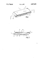
- FIG. 1 shows a perspective view of a clip according to the present invention.
- FIG. 2 shows the FIG. 1 clip shown along the lines 2--2.
- clip 10 includes metal housing 12, steel spring member 14 and plastic top structure 16 having a recess 17.
- Top structure 16 is attached to support structure 12 by plastic rivets 18 which are ultrasonically welded or staked to corresponding holes of support structure 12.
- Support structure 12 includes top portion 22, bottom portion 24 and connecting portion 26.
- Top portion 22 defines hole 28 having opposing surfaces 30, 32.
- Spring member 14 is resiliently mounted between opposing surfaces 30, 32 as well as between top portion 22 and the top of recess 17 of top structure 16.
- clip 10 is constructed by riveting top structure 16 to support structure 12, slipping spring member 14 between top portion 22 and bottom portion 24 such that one end of spring member 14 contacts opposing portion 30 and the top of recess 17. Spring member 14 is then biased until the other end can slip past portion 32. This end is then released allowing spring member 14 to exert a force against opposing portions 30, 32, bottom portion 24 and the top of recess 17.
- a flat object e.g., paper currency
- top structure 16 may easibly be removed for engraving.
- information e.g., advertising, may be printed on top structure 16.
Landscapes
- Clamps And Clips (AREA)
Abstract
A clip having a spring member held at its ends between the edges of a hole in a first wall member and a stop member attached to the first wall member, the clip having a second wall member that is spaced from the first wall member.
Description
The invention relates to devices for releasably retaining flat objects.
1. Background of the Invention
It is known to releasably retain flat objects such as paper currency between a fixed member and a spring member of a clip and to secure a spring member within a clip by placing the spring member between a tongue of a first portion and a square-shaped hole of a second portion, as in Anderson U.S. Pat. No. 3,049,772, "Necktie Clasp", granted Aug. 31, 1962.
2. Summary of the Invention
I have discovered that such a clip desirably has a spring member held at its end between the edges of a hole in a spring housing and stop means.
In preferred embodiments the spring member is flattenable in use and movable then with respect to the hole edges, a housing wall toward which the spring member is biased is movable relative to the hole edges in use, the housing is of metal, and the stop means are portions of a plastic cap riveted to the housing means.
The presently preferred embodiment is as follows.
FIG. 1 shows a perspective view of a clip according to the present invention.
FIG. 2 shows the FIG. 1 clip shown along the lines 2--2.
Referring to FIGS. 1 and 2, clip 10 includes metal housing 12, steel spring member 14 and plastic top structure 16 having a recess 17. Top structure 16 is attached to support structure 12 by plastic rivets 18 which are ultrasonically welded or staked to corresponding holes of support structure 12.
Referring to FIGS. 1 and 2, clip 10 is constructed by riveting top structure 16 to support structure 12, slipping spring member 14 between top portion 22 and bottom portion 24 such that one end of spring member 14 contacts opposing portion 30 and the top of recess 17. Spring member 14 is then biased until the other end can slip past portion 32. This end is then released allowing spring member 14 to exert a force against opposing portions 30, 32, bottom portion 24 and the top of recess 17.
In operation, a flat object, e.g., paper currency, is releasably retained between spring member 14 and bottom portion 24. Also, top structure 16 may easibly be removed for engraving. Additionally, information, e.g., advertising, may be printed on top structure 16.
Claims (4)
1. A clip for releasably retaining a flat object comprising
opposing first and second elongated wall members that are connected to each other at one end only and spaced from each other so as to define a flat region therebetween for receiving said flat object,
said first wall member having a first surface and a second surface,
said second surface facing said second wall member,
said first wall member having an elognated hole through it with edges at two ends,
a stop member connected to said first wall member and spaced from said first surface, and
an elognated spring member having a middle portion that extends between said two edges of said hole toward said second wall member, said elongated spring member also having ends held between said edges and said stop member.
2. The apparatus of claim 1 wherein said spring member is flattenable and movable with the respect to said hole edges.
3. The apparatus of claim 1 wherein said first and second wall members are made of metal.
4. The apparatus of claim 1 wherein said stop member is a plastic cap riveted to said spring housing.
Priority Applications (1)
| Application Number | Priority Date | Filing Date | Title |
|---|---|---|---|
| US07/345,946 US4967453A (en) | 1989-05-01 | 1989-05-01 | Resilient clip |
Applications Claiming Priority (1)
| Application Number | Priority Date | Filing Date | Title |
|---|---|---|---|
| US07/345,946 US4967453A (en) | 1989-05-01 | 1989-05-01 | Resilient clip |
Publications (1)
| Publication Number | Publication Date |
|---|---|
| US4967453A true US4967453A (en) | 1990-11-06 |
Family
ID=23357228
Family Applications (1)
| Application Number | Title | Priority Date | Filing Date |
|---|---|---|---|
| US07/345,946 Expired - Fee Related US4967453A (en) | 1989-05-01 | 1989-05-01 | Resilient clip |
Country Status (1)
| Country | Link |
|---|---|
| US (1) | US4967453A (en) |
Cited By (7)
| Publication number | Priority date | Publication date | Assignee | Title |
|---|---|---|---|---|
| US5495644A (en) * | 1994-06-14 | 1996-03-05 | Mesher; James A. | Ornamental gripping device for holding gift cards onto gift packages |
| US5539159A (en) * | 1991-05-17 | 1996-07-23 | Ncr Corporation | Handwriting capture device |
| US5673952A (en) * | 1995-05-22 | 1997-10-07 | Jim A. Chezem | Door stop |
| WO1999042303A1 (en) * | 1998-02-20 | 1999-08-26 | Luntz S Richard | Writing instrument |
| USD485162S1 (en) | 2002-04-05 | 2004-01-13 | Jake Wadsworth | Clip assembly |
| US10252564B2 (en) * | 2014-06-24 | 2019-04-09 | Keum Tae JANG | Paper clip |
| US12297678B1 (en) * | 2023-07-05 | 2025-05-13 | Erik Kelsey Wade | Device to slow or stop a door from opening |
Citations (11)
| Publication number | Priority date | Publication date | Assignee | Title |
|---|---|---|---|---|
| US386513A (en) * | 1888-07-24 | William e | ||
| US613890A (en) * | 1898-11-08 | Half to william o | ||
| US1405024A (en) * | 1922-01-31 | smith | ||
| US1869032A (en) * | 1931-02-20 | 1932-07-26 | Clyde V Van Buren | Loose leaf holder |
| FR1159029A (en) * | 1956-10-09 | 1958-06-23 | Towel clip | |
| CA636630A (en) * | 1962-02-13 | V. Anderson Olof | Jewelry clasp | |
| DE1129010B (en) * | 1961-01-20 | 1962-05-03 | Kurt Lorber | Cloth clamp |
| US3049772A (en) * | 1959-12-16 | 1962-08-21 | Anson Inc | Necktie clasp |
| US3141213A (en) * | 1962-12-04 | 1964-07-21 | Scovill Manufacturing Co | Pass case binder |
| DE1191942B (en) * | 1955-08-24 | 1965-04-29 | Paul Nievergelt | Terminal strip for hanging flat objects such as drawings, documents, etc. like |
| CA1001037A (en) * | 1973-03-15 | 1976-12-07 | John A. Grant | Device for holding a book open |
-
1989
- 1989-05-01 US US07/345,946 patent/US4967453A/en not_active Expired - Fee Related
Patent Citations (11)
| Publication number | Priority date | Publication date | Assignee | Title |
|---|---|---|---|---|
| US386513A (en) * | 1888-07-24 | William e | ||
| US613890A (en) * | 1898-11-08 | Half to william o | ||
| US1405024A (en) * | 1922-01-31 | smith | ||
| CA636630A (en) * | 1962-02-13 | V. Anderson Olof | Jewelry clasp | |
| US1869032A (en) * | 1931-02-20 | 1932-07-26 | Clyde V Van Buren | Loose leaf holder |
| DE1191942B (en) * | 1955-08-24 | 1965-04-29 | Paul Nievergelt | Terminal strip for hanging flat objects such as drawings, documents, etc. like |
| FR1159029A (en) * | 1956-10-09 | 1958-06-23 | Towel clip | |
| US3049772A (en) * | 1959-12-16 | 1962-08-21 | Anson Inc | Necktie clasp |
| DE1129010B (en) * | 1961-01-20 | 1962-05-03 | Kurt Lorber | Cloth clamp |
| US3141213A (en) * | 1962-12-04 | 1964-07-21 | Scovill Manufacturing Co | Pass case binder |
| CA1001037A (en) * | 1973-03-15 | 1976-12-07 | John A. Grant | Device for holding a book open |
Cited By (8)
| Publication number | Priority date | Publication date | Assignee | Title |
|---|---|---|---|---|
| US5539159A (en) * | 1991-05-17 | 1996-07-23 | Ncr Corporation | Handwriting capture device |
| US5495644A (en) * | 1994-06-14 | 1996-03-05 | Mesher; James A. | Ornamental gripping device for holding gift cards onto gift packages |
| US5673952A (en) * | 1995-05-22 | 1997-10-07 | Jim A. Chezem | Door stop |
| WO1999042303A1 (en) * | 1998-02-20 | 1999-08-26 | Luntz S Richard | Writing instrument |
| US5996185A (en) * | 1998-02-20 | 1999-12-07 | Luntz; S. Richard | Writing instrument |
| USD485162S1 (en) | 2002-04-05 | 2004-01-13 | Jake Wadsworth | Clip assembly |
| US10252564B2 (en) * | 2014-06-24 | 2019-04-09 | Keum Tae JANG | Paper clip |
| US12297678B1 (en) * | 2023-07-05 | 2025-05-13 | Erik Kelsey Wade | Device to slow or stop a door from opening |
Similar Documents
| Publication | Publication Date | Title |
|---|---|---|
| US5129126A (en) | Structure of fastening device for fastening two things together | |
| FR2697301B1 (en) | Rivet device with zero insertion force. | |
| US4967453A (en) | Resilient clip | |
| US4948172A (en) | Combined clip board and pen holder | |
| KR940015139A (en) | Key safety device | |
| US6256846B1 (en) | Fastening device | |
| ES254117U (en) | Securing clips | |
| KR900011511A (en) | Securely engaged pipettes and their supports | |
| DE68900534D1 (en) | RECEIVING ELEMENT FOR A QUICK-RELEASE FASTENING DEVICE. | |
| US4017944A (en) | Shoulder bag clasp | |
| US3974543A (en) | Combination key ring and note holder device | |
| US2504765A (en) | Clip | |
| US1310202A (en) | Holder eor meuti-caeds and the like | |
| US4170807A (en) | Fastener means | |
| JPS645429Y2 (en) | ||
| JPS6215211Y2 (en) | ||
| KR880001526Y1 (en) | Cloak for Billboard | |
| US2777179A (en) | Clip | |
| JPS6024617Y2 (en) | Notebook scissors | |
| EP0943818B1 (en) | Clip for identification cards | |
| JPH0667046U (en) | Heart-shaped seal | |
| JP3014518U (en) | Visual equipment with pinhole | |
| KR970005944A (en) | Front panel anti-drop device with detachable car audio | |
| KR900701206A (en) | Plastic key and key carrier combination | |
| KR830003840A (en) | Brass Retainer |
Legal Events
| Date | Code | Title | Description |
|---|---|---|---|
| FEPP | Fee payment procedure |
Free format text: PAYOR NUMBER ASSIGNED (ORIGINAL EVENT CODE: ASPN); ENTITY STATUS OF PATENT OWNER: SMALL ENTITY |
|
| FPAY | Fee payment |
Year of fee payment: 4 |
|
| REMI | Maintenance fee reminder mailed | ||
| LAPS | Lapse for failure to pay maintenance fees | ||
| FP | Lapsed due to failure to pay maintenance fee |
Effective date: 19981106 |
|
| STCH | Information on status: patent discontinuation |
Free format text: PATENT EXPIRED DUE TO NONPAYMENT OF MAINTENANCE FEES UNDER 37 CFR 1.362 |