US495835A - redfield - Google Patents
redfield Download PDFInfo
- Publication number
- US495835A US495835A US495835DA US495835A US 495835 A US495835 A US 495835A US 495835D A US495835D A US 495835DA US 495835 A US495835 A US 495835A
- Authority
- US
- United States
- Prior art keywords
- matrix
- pin
- machine
- magnet
- movement
- Prior art date
- Legal status (The legal status is an assumption and is not a legal conclusion. Google has not performed a legal analysis and makes no representation as to the accuracy of the status listed.)
- Expired - Lifetime
Links
- 239000011159 matrix material Substances 0.000 description 13
- 230000001276 controlling effect Effects 0.000 description 3
- 238000005259 measurement Methods 0.000 description 2
- CVRALZAYCYJELZ-UHFFFAOYSA-N O-(4-bromo-2,5-dichlorophenyl) O-methyl phenylphosphonothioate Chemical compound C=1C=CC=CC=1P(=S)(OC)OC1=CC(Cl)=C(Br)C=C1Cl CVRALZAYCYJELZ-UHFFFAOYSA-N 0.000 description 1
- 230000000881 depressing effect Effects 0.000 description 1
- 238000010586 diagram Methods 0.000 description 1
- 230000000694 effects Effects 0.000 description 1
- 239000011810 insulating material Substances 0.000 description 1
- 239000002184 metal Substances 0.000 description 1
- 230000001105 regulatory effect Effects 0.000 description 1
Images


Classifications
-
- B—PERFORMING OPERATIONS; TRANSPORTING
- B41—PRINTING; LINING MACHINES; TYPEWRITERS; STAMPS
- B41J—TYPEWRITERS; SELECTIVE PRINTING MECHANISMS, i.e. MECHANISMS PRINTING OTHERWISE THAN FROM A FORME; CORRECTION OF TYPOGRAPHICAL ERRORS
- B41J3/00—Typewriters or selective printing or marking mechanisms characterised by the purpose for which they are constructed
- B41J3/38—Typewriters or selective printing or marking mechanisms characterised by the purpose for which they are constructed for embossing, e.g. for making matrices for stereotypes
Definitions
- My invention relates to machines for form- (0 ing stereotype matrices by the successive impression of independent type-dies, and the improvements will be hereinafter fully described and particularly pointed out in the claims.
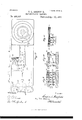
- Fig. 1 is a side elevation of the machine; Fig. 2 a plan; Fig. 3 a central longitudinal section on the line 0c.t of Figs. 1 and 4.
- Fig. 4 is also a plan with portions of the exterior of the machine removed or broken away to show the interior.
- Fig. 5 is an enlarged plan, in detail, of the escapement portion.
- Fig. 6 is also a plan of the same, partly in horizontal section.
- Fig. 1 is a side elevation of the machine
- Fig. 2 a plan
- Fig. 3 a central longitudinal section on the line 0c.t of Figs. 1 and 4.
- Fig. 4 is also a plan with portions of the exterior of the machine removed or broken away to show the interior.
- Fig. 5 is an enlarged plan, in detail, of the escapement portion.
- Fig. 6 is also a plan of the same, partly in horizontal section.
- Fig. 6 is a bottom view in detail of the levers 36 and 37.
- Fig. 7 is aside elevation of the same.
- Fig. 8 is a central longitudinal section of the same.
- Fig. 9 is a zigzag section transverse of the machine through the space-throwing keys shown in Fig. 2.
- Fig. 10 is a similar section at right angles to Fig. 9 and the two figures show the manner of making the electric connections for spacing the matrix impressions.
- Fig. 11 is an end view of the electrical contact plates showing the manner of making electrical connections with the magnets; and
- Fig. 12 is an outline plan of the machine showing the course of the electric current.
- 1 is the frame of the machine.
- 2 is an upper portion of the frame provided for supporting the die-impressing devices
- 3 is the die-carrying lever connected by a pivot-pin 4 to a cross-head 5 in the guides 6.
- 7 is the indicator-pin carried on the outer arm of the lever; 8 and 9 the die-carrying frame on the inner end of the lever, and 10 the type-dies carried therein.
- the inifpressing device consists of a two-part clutch-box 13 carried on a vertical shaft 14 that is rotated by means of a combined pulley and flywheel 15 and 16.
- -On the lower member of the clutch-box is a pin 17 that is engaged by a spring-stop 1 8 to stop rotation of such memher and cause the inclined surfaces of thetwo co-operatin g members to move the lower member downward to produce a plunger thrust.
- the stop 18 is carried on a rod 19 that has a head which is engaged by a spring catch 20 to hold it away from the clutch, and the spring catch is arranged to be freed from engagement by the blow of a spring hammer 21 operated by an electro-magnet 22.
- 27 is a rack having one end connected to the carriage 12 and its toothed portion engaged by pinions 28 and 29.
- a motor-spring 30 To the shaft of the pinion 28 is connected one end of a motor-spring 30, the other end of which is attached to a post 31, and 5 the force of the spring tends to move the rack in the direction of the arrow 2.
- a spring 32 To the shaft of the pinion 29 is connected a spring 32 also tending to turn the pinion and move the rack in the direction of the arrow z.
- ICO on this shaft is mounted a ratchet-wheel 33, and, to restrain its movement a dog 34 is cona r i r 495,835
- a lever 36 is pivoted to the under side of this bar near the center of the scapewheel, and at the under side of the lever 36 lsa lever 37 pivoted on the shaft of the scapewheel and having a pin 38 extending upward through a slot 39 in the lever 36, so that the lever 36 and the bar may slide longitudinally.
- the lever 36 has at its under side a dog 40 for engaging the teeth of the scapewheel when the bar has been moved longitudinally inward and the dog 34 released.
- the inner end of the bar is guided in its movements by means of a link 41 pivoted thereto and to a post 41.
- the outer portion 42 of'the bar 35 is of segmental shape, and thebar is moved inward to cause disengagement of one detent and engagement of the other by means of the pressure on its end 42 of the springs 43 on the pins 44.
- These pins are held normally from engagement with the end '42 of the bar by spring catches 45 engaging heads 46 on the pins.
- the force of its spring 43 thrusts the pin inward in the direction of the arrow 2' and causes a collar 47 on the pin to engage the head 42 and carry the bar inward.
- This movement causes the release of the holding dog 34 and engagement of the dog 40 and permits the rotation of the scape-Wheel in the direction indicated by the arrow 2 until an inclined surface 48 on the face of the lever 37 engages the end of the protruding pin 44 and returns it far enough to be re-engaged by its spring catch 45.
- a spring 49 attached to the frame 50 exerts its force to move the bar 35 outward and cause re-engagement of the holding-dog 34 with the scape-wheel, and then, the rotation of the scape-wheel being stopped, the force of a spring 51, one end of which is attached to the bar 35 and the other to the lever 36, returns the levers from the position shown in Fig. 6 to that shown in Figs. 4 and 5, the return movement being checked by a regulating screw 52.
- the spring catches 45 are operated by hammers 53 carried by spring levers 54 that are fulcrumed at 55 and carry armatures 61 that are operated by the electro-magnets 56.
- the devices are arranged for six degrees of movement, each of which is controlled by a separate magnet 56 and the circuit is closed with the appropriate magnet by the depression of the indicator-pin 7 through the indexplate to contact with one of the fixed conducting plates 57 beneath the index-plate.
- Each of the plates 57 of which there are six, has a pendent pin 58 that extends through the other plates and has a flattened end that passes between a pair of metallic clamping arms 59 and to these clamping arms are connected wires 60 that make the electrical connections between them and their respective magnets 56.
- the depression of theindicatorpin to contactwith any of these plates, (which plates are similar to those shown in my patent No.
- pins are arranged radially in a plane parallel to that of the scape-wheel and their positions determine the extent of movement of the levers 36 and 37 between the position at which they are at rest, and that of the pin that has been operated and thrust inward to provide a stop for them.
- the use of the first pin of the series would cause a movement of the escapement and consequent movement of the matrix-carriage equal to the unit of movement; the operation of the second pin that of a multiple of the unit of movement; that of the third pin, a movement proportioned to the third degree or multiple of movement; and so on, with each of the pins of the series.
- the movement of the lever 3 to bring the indicator-pin to co-incidence with any of the openings of the index-plate moves a diecorresponding with the selected character on the index-plate, to the printing point over the matrix-carriage, and following this movement by the depression of the indicator-pin completes the electric circuit through the appropriate magnet 56 for producing a consequent movement of the matrix-carriage the proper distance to space for a letter and the completion of the circuit through the magnet 22 simultaneously with its completion through the magnet 56, causes the depression of the plunger to thrust the die into the matrix-body.
- the feeding and impressing devices and their connections are so constructed and arrangedv that the time required to make the necessary feed movements is less than that required to cause the die'to be thrust to contact with the matrix.
- the speed at which the impression device is rotated is slow enough to permit the feed devices to complete their advance or feed movement in the interval occurring between the release of the stop-pin 18 and the impingement of the die on the matrix, and hence, although the movements of the feed and impressing devices begin simultaneously the former are completed before the die can reach the matrix-body.
- a series of spring spacing-levers 62 fastened to a metal bar 63 that is insulated from the bed, and to this bar is connected a branch from the main conducting wire, and beneath the ends of these levers is a corresponding series of pins 64 surrounded by suitable insulating material.
- the pins are pointed and their ends engaged between spring clamps 65, from which extend wires 66 to the magnets 56.
- the depression of any one of the levers 62 to contact with a pin 64 will complete an electric circuit and cause the operation of the escapement devices, as hereinbefore described, without completing the circuit through the impression device magnet 22.
- a spacing, of the desired extent of measurement without impressions can be made.
- the course of the electric current for the several operative parts of the machine is indicated in the diagram, Fig. 12.
- the circuit is for spacing without making impressions, as last above referred to, its course is through the broken lines a and a to the appropriate plate 57, thence through one of the wires a to the magnet 56 connected to such plate, and thence through one of the wires a to the return wire a.
- the circuit is through the magnet 22 for operating the impression device, then its course is through the wires a and b to the magnet 22; thence through I) to a portion of the machine frame; thence through the lever 3 and the indicator-pin to the selected plate 57 and thence to the appropriate magnet 56 and through its connecting wire a to the return wire a.
- a disk 67 that turns with the spindle and has figures or graduations 68 in circular arrangement on its face to indicate the feed movements, and in the frame cover is a slot 69,
- the operative parts of the machine are almost entirely concealed, as shown in Figs. 1 and 2, and access to them can be had by removing cap-pieces.
- the lever 3 and its dieframe can be readily withdrawn from its guides, after which a cap-piece 70, carrying the index 24 and the cond noting-plates 57, can be lifted off, exposing to view the escapement devices.
- the pins 58 being attached to the plates 57, lift out of the clamping arms 59 and re-enter when the cap is replaced.
- a cappiece 71 can be likewise lifted 01f the middle portion of the machine, exposing the disk 67 and a portion of the escapement.
- the spacing-levers 62 and their contact-pins 64 are removed with the cover, the pins sliding out of the clasps 65 to re-enter upon return of the plate.
- the upper portion 2 of the frame may also in like manner be lifted off, removing with it the impression device.
- These several cap-pieces may be secured to the base of the frame by dowel-pins or screws 7 2.
- a matrix making machine having its frame provided with removable cover-sections carrying an index plate and the spacingkeys and pendent contacts, and its base provided with spring jaws connected to the circuit wires and cooperating with said pendent contacts, substantially as and for the purpose set forth. 7
- a die-impressing device arranged to operate upon being released and to replace its releasing device upon making a thrust
- a variable 'feed mechanism arranged to operate upon being engaged by any one of a series of releasing devices and to replace the operative releasing device upon making a feed movement
- separate magnets for each of said releasing devices and suitable electrical connections, whereby a circuit may be completed through the magnet connected with the impressing device to any one of the magnets connected with the feed mechanism, substantially as set forth.
- a matrix machine having an elec: trically controlled die-impressing device and a variable matrix-feed mechanism controlled by a series of releasing devices, magnets for operating the releasing devices, and suitable electric connections for completing a circuit through any one of such magnets without including the impressing device in the circuit, substantially as set forth.
- variable feed mechanism adapted to operate upon being released
- impression device and a controlling device therefor adapted to operate upon being released
- electrical devices for actuating such releasing and controlling devices substantially as set forth.
- a rotary impression device adapted to thrust upon being intercepted, electrically controlled intercepting devices therefor, a variable feed mechanism and electrically controlled operating devices therefor, a character-selecting device carrying a circuit closerand circuit connections arranged to energize simultaneously both the magnet for the impression device and feed mechanism upon contact of said circuit closer, substantially as set forth.
- a controlling device therefor adapted to be operative upon being released, a variable feed mechanism adapted to be operative upon being released,and electro-magnets in a common circuit and arranged to effect the simultaneous operation of both the feed mechanism and impressing device, substantially as set forth.
- an impression device In a matrix machine, an impression device, a releasing magnet therefor for causing plunger thrusts, an escapement feed, magnets for releasing it, and keys and connections for producing feed movements without causing the operation of the impression device, sub stantially as set forth.
Landscapes
- Transmission Devices (AREA)
Description
(No Model.) 4 eeeeeeeeee e1; 1.
0. L. REDFIELD;
} MATRIX MAKING MACHINE. No; 495,835. Patented Apr. 18, 1898.
(No Model.) 4 Sheets-Sheet 3.
0. L. RE DFIELD. MATRIX MAKING MAGHINE.
Patented Apr. 18, 1893.
awue/wboz 1006/ ca, (MW as ZZZ W W m: NORRIS nsrzks ca, PHOTO-LITHDH WASHINGTON, o. c.
- (No Model.) 4 Sheets-Sheet 4.
' O. L. REDFIELD.
MATRIX MAKING MACHINE.
No. 495,835. Patented Apr. 18, 1893.
nm, WASH UNITED STATES PATENT OFFICE.
CASPER L. REDFIELD, OF MINNEAPOLIS, MINNESOTA, ASSIGNOR, BY MESNE ASSIGNMENTS, TO THE CHICAGO MATRIX MACHINE COMPANY.
MATRIX-MAKING MACHINE.
SPECIFICATION forming part of Letters Patent No. 495,835, dated April 18, 1893.
Application filed May 1 1889. Serial No. 309,288. (No model.)
To all whom it may concern.-
Be it known that I, CASPER L. REDFIELD, a citizen of the United States, residing at Minneapolis, in the county of Hennepin and State of Minnesota, have invented certain new and useful Improvements in Matrix-Making Machines, of which the following is a specification.
My invention relates to machines for form- (0 ing stereotype matrices by the successive impression of independent type-dies, and the improvements will be hereinafter fully described and particularly pointed out in the claims.
In the accompanying drawings in which my invention is illustratedz-Figure 1 is a side elevation of the machine; Fig. 2 a plan; Fig. 3 a central longitudinal section on the line 0c.t of Figs. 1 and 4. Fig. 4 is also a plan with portions of the exterior of the machine removed or broken away to show the interior. Fig. 5 is an enlarged plan, in detail, of the escapement portion. Fig. 6 is also a plan of the same, partly in horizontal section. Fig.
6 is a bottom view in detail of the levers 36 and 37. Fig. 7 is aside elevation of the same. Fig. 8 is a central longitudinal section of the same. Fig. 9 is a zigzag section transverse of the machine through the space-throwing keys shown in Fig. 2. Fig. 10 is a similar section at right angles to Fig. 9 and the two figures show the manner of making the electric connections for spacing the matrix impressions. Fig. 11 is an end view of the electrical contact plates showing the manner of making electrical connections with the magnets; and Fig. 12 is an outline plan of the machine showing the course of the electric current.
4 In said drawings, 1 is the frame of the machine.
2 is an upper portion of the frame provided for supporting the die-impressing devices, and 3 is the die-carrying lever connected by a pivot-pin 4 to a cross-head 5 in the guides 6.
7 is the indicator-pin carried on the outer arm of the lever; 8 and 9 the die-carrying frame on the inner end of the lever, and 10 the type-dies carried therein.
11 is a reciprocating plunger operated by the impressing device for depressing the presented type-dies into a matrix-body M carried on the matrix-carriage 12. The inifpressing device consists of a two-part clutch-box 13 carried on a vertical shaft 14 that is rotated by means of a combined pulley and flywheel 15 and 16. -On the lower member of the clutch-box is a pin 17 that is engaged by a spring-stop 1 8 to stop rotation of such memher and cause the inclined surfaces of thetwo co-operatin g members to move the lower member downward to produce a plunger thrust. The stop 18 is carried on a rod 19 that has a head which is engaged by a spring catch 20 to hold it away from the clutch, and the spring catch is arranged to be freed from engagement by the blow of a spring hammer 21 operated by an electro-magnet 22.
For fuller description of devices of the same general character reference maybehad to my patents Nos. 429,737, 429,738, 429,739, 429,742, of June 10, 1890.
It will be understood that in operating the lever 3, the movement of the indicator-pin 7 to co-incidence with the desired letter indi- 7 5 cated at one of the openings 23 in the character-index 24, will move the appropriate die 10 to position immediately under the plunger 11 and over a guide-hole 25 in a plate 26 overlying the matrix-carriage; and that upon the occurrence of a reciprocation of the plunger, the selected die 10 will be thrust downward through the guide-hole to make an impression in the matrix-body supported by the carriage. Before another impression can then be made Without injuring the last impression it is necessary to move the matrix-carriage in lateral direction sufficiently to space for the next letter. This is accomplished in the manner following: 27 is a rack having one end connected to the carriage 12 and its toothed portion engaged by pinions 28 and 29. To the shaft of the pinion 28 is connected one end of a motor-spring 30, the other end of which is attached to a post 31, and 5 the force of the spring tends to move the rack in the direction of the arrow 2. To the shaft of the pinion 29 is connected a spring 32 also tending to turn the pinion and move the rack in the direction of the arrow z. And ICO on this shaft is mounted a ratchet-wheel 33, and, to restrain its movement a dog 34 is cona r i r 495,835
nected to the under side of abar 35 that spans the wheel. A lever 36 is pivoted to the under side of this bar near the center of the scapewheel, and at the under side of the lever 36 lsa lever 37 pivoted on the shaft of the scapewheel and having a pin 38 extending upward through a slot 39 in the lever 36, so that the lever 36 and the bar may slide longitudinally. The lever 36 has at its under side a dog 40 for engaging the teeth of the scapewheel when the bar has been moved longitudinally inward and the dog 34 released. The inner end of the bar is guided in its movements by means of a link 41 pivoted thereto and to a post 41. The outer portion 42 of'the bar 35 is of segmental shape, and thebar is moved inward to cause disengagement of one detent and engagement of the other by means of the pressure on its end 42 of the springs 43 on the pins 44. These pins are held normally from engagement with the end '42 of the bar by spring catches 45 engaging heads 46 on the pins. When one of the catches 45 is released, the force of its spring 43 thrusts the pin inward in the direction of the arrow 2' and causes a collar 47 on the pin to engage the head 42 and carry the bar inward. This movement causes the release of the holding dog 34 and engagement of the dog 40 and permits the rotation of the scape-Wheel in the direction indicated by the arrow 2 until an inclined surface 48 on the face of the lever 37 engages the end of the protruding pin 44 and returns it far enough to be re-engaged by its spring catch 45. Thereupon a spring 49 attached to the frame 50 exerts its force to move the bar 35 outward and cause re-engagement of the holding-dog 34 with the scape-wheel, and then, the rotation of the scape-wheel being stopped, the force of a spring 51, one end of which is attached to the bar 35 and the other to the lever 36, returns the levers from the position shown in Fig. 6 to that shown in Figs. 4 and 5, the return movement being checked by a regulating screw 52. The spring catches 45 are operated by hammers 53 carried by spring levers 54 that are fulcrumed at 55 and carry armatures 61 that are operated by the electro-magnets 56.
The devices are arranged for six degrees of movement, each of which is controlled by a separate magnet 56 and the circuit is closed with the appropriate magnet by the depression of the indicator-pin 7 through the indexplate to contact with one of the fixed conducting plates 57 beneath the index-plate. Each of the plates 57, of which there are six, has a pendent pin 58 that extends through the other plates and has a flattened end that passes between a pair of metallic clamping arms 59 and to these clamping arms are connected wires 60 that make the electrical connections between them and their respective magnets 56. The depression of theindicatorpin to contactwith any of these plates, (which plates are similar to those shown in my patent No. 416,742, of December 10, 1889,) completes an electric circuit through a wire connected to the magnet 22, thence through a portion of the frame of the machine, thence through the lever 3, the engaged plate 57 and its contact devices to the appropriate magnet 56; and, upon the completion of such circuit, the armature 61, attached to the lever 54, is drawn to its magnet causing the spring hammer to strike a blow against the under side of the proper spring catch 45 and release it from engagement, and so permit the spring 43, on the disengaged pin, to thrust it inward and engage the bar 35 and move the latter to release the holding dog 34 and cause engagement of the dog 40 and thus permit rotation of the escapement-wheel in the manner heretofore described. These pins are arranged radially in a plane parallel to that of the scape-wheel and their positions determine the extent of movement of the levers 36 and 37 between the position at which they are at rest, and that of the pin that has been operated and thrust inward to provide a stop for them. Thus the use of the first pin of the series would cause a movement of the escapement and consequent movement of the matrix-carriage equal to the unit of movement; the operation of the second pin that of a multiple of the unit of movement; that of the third pin, a movement proportioned to the third degree or multiple of movement; and so on, with each of the pins of the series. Hence, in operating the machine, the movement of the lever 3 to bring the indicator-pin to co-incidence with any of the openings of the index-plate, moves a diecorresponding with the selected character on the index-plate, to the printing point over the matrix-carriage, and following this movement by the depression of the indicator-pin completes the electric circuit through the appropriate magnet 56 for producinga consequent movement of the matrix-carriage the proper distance to space for a letter and the completion of the circuit through the magnet 22 simultaneously with its completion through the magnet 56, causes the depression of the plunger to thrust the die into the matrix-body. It will be noted that while the magnet 22 and the selected magnet 56 are simultaneously thrown into circuit and so energized, the feeding and impressing devices and their connections are so constructed and arrangedv that the time required to make the necessary feed movements is less than that required to cause the die'to be thrust to contact with the matrix. The completion of the feed movement prior to the impression of the die is effected by reason of the strong tension of the motorspring 32 and the short movement of the projected pin 44, which permits a very quick movement of the feed devices, while, on the other hand, when the spring-stop 18 has been actuated a-short interval of time occurs,during a partial revolution of the impression device, before the stop engages the pin 17 to IIO interrupt the revolution, and another interval of time, equal to nearly a half revolution of the impression device, occurs before the die thrust upon by the plunger can reach the matrix-body. The speed at which the impression device is rotated is slow enough to permit the feed devices to complete their advance or feed movement in the interval occurring between the release of the stop-pin 18 and the impingement of the die on the matrix, and hence, although the movements of the feed and impressing devices begin simultaneously the former are completed before the die can reach the matrix-body. By these means the speed of the machines work is enhanced, for the delay of closing a branch or independent circuit to energize the impressing device magnet, after completion of the feed movement, is avoided.
To enable matrix feed movements to be made without causing the impression device to operate, there is provided a series of spring spacing-levers 62 fastened to a metal bar 63 that is insulated from the bed, and to this bar is connected a branch from the main conducting wire, and beneath the ends of these levers is a corresponding series of pins 64 surrounded by suitable insulating material. The pins are pointed and their ends engaged between spring clamps 65, from which extend wires 66 to the magnets 56. The depression of any one of the levers 62 to contact with a pin 64 will complete an electric circuit and cause the operation of the escapement devices, as hereinbefore described, without completing the circuit through the impression device magnet 22. Thus a spacing, of the desired extent of measurement without impressions can be made. These devices are similar to those made the subject-matter of my patent No. 448,994, of March 24, 1891.
The course of the electric current for the several operative parts of the machine is indicated in the diagram, Fig. 12. When the circuit is for spacing without making impressions, as last above referred to, its course is through the broken lines a and a to the appropriate plate 57, thence through one of the wires a to the magnet 56 connected to such plate, and thence through one of the wires a to the return wire a. If the circuit is through the magnet 22 for operating the impression device, then its course is through the wires a and b to the magnet 22; thence through I) to a portion of the machine frame; thence through the lever 3 and the indicator-pin to the selected plate 57 and thence to the appropriate magnet 56 and through its connecting wire a to the return wire a.
To enable an operator to ascertain the position of the matrix-body and the number of units of measurement it has been fed, there is mounted on the spindle of the pinion 28, a disk 67, that turns with the spindle and has figures or graduations 68 in circular arrangement on its face to indicate the feed movements, and in the frame cover is a slot 69,
through which a portion of the indicatormarks can be viewed.
The operative parts of the machine are almost entirely concealed, as shown in Figs. 1 and 2, and access to them can be had by removing cap-pieces. The lever 3 and its dieframe can be readily withdrawn from its guides, after which a cap-piece 70, carrying the index 24 and the cond noting-plates 57, can be lifted off, exposing to view the escapement devices. The pins 58 being attached to the plates 57, lift out of the clamping arms 59 and re-enter when the cap is replaced. A cappiece 71 can be likewise lifted 01f the middle portion of the machine, exposing the disk 67 and a portion of the escapement. The spacing-levers 62 and their contact-pins 64 are removed with the cover, the pins sliding out of the clasps 65 to re-enter upon return of the plate. The upper portion 2 of the frame may also in like manner be lifted off, removing with it the impression device. These several cap-pieces may be secured to the base of the frame by dowel-pins or screws 7 2.
What I claim, and desire to secure by Letters Patent herein, is
1. The combination with a matrix-carriage having a rack for moving it, of a rotating graduated disk operated by a pinion engaged by said rack, substantially as set forth.
' 2. The combination, in an electrically operated matrix-machine, of a frame having a removabe cover-section carrying an index-plate providing pendent contacts, co-operating with fixed clamping jaws provided on the base, substantially as set forth.
3. The combination in an electrically operated matrix machine, of a frame having aremovable cover-section carrying spacing-keys and pendent contacts; and clamping jaws cooperating therewith and fixed on the base, substantially as set forth.
4. A matrix making machine having its frame provided with removable cover-sections carrying an index plate and the spacingkeys and pendent contacts, and its base provided with spring jaws connected to the circuit wires and cooperating with said pendent contacts, substantially as and for the purpose set forth. 7
5. In a matrix machine, in combination, a die-impressing device arranged to operate upon being released and to replace its releasing device upon making a thrust, a variable 'feed mechanism arranged to operate upon being engaged by any one of a series of releasing devices and to replace the operative releasing device upon making a feed movement, separate magnets for each of said releasing devices, and suitable electrical connections, whereby a circuit may be completed through the magnet connected with the impressing device to any one of the magnets connected with the feed mechanism, substantially as set forth.
6. In a matrix machine, having an elec: trically controlled die-impressing device and a variable matrix-feed mechanism controlled by a series of releasing devices, magnets for operating the releasing devices, and suitable electric connections for completing a circuit through any one of such magnets without including the impressing device in the circuit, substantially as set forth.
7. In a matrix machine, a variable feed mechanism adapted to operate upon being released, an impression device and a controlling device therefor adapted to operate upon being released, and electrical devices for actuating such releasing and controlling devices, substantially as set forth.
8. In a matrix machine, a rotary impression device adapted to thrust upon being intercepted, electrically controlled intercepting devices therefor, a variable feed mechanism and electrically controlled operating devices therefor, a character-selecting device carrying a circuit closerand circuit connections arranged to energize simultaneously both the magnet for the impression device and feed mechanism upon contact of said circuit closer, substantially as set forth.
9. In amatrix machine,adie-impressing device, a controlling device therefor adapted to be operative upon being released, a variable feed mechanism adapted to be operative upon being released,and electro-magnets in a common circuit and arranged to effect the simultaneous operation of both the feed mechanism and impressing device, substantially as set forth.
10. In a matrix machine, an impression device, a releasing magnet therefor for causing plunger thrusts, an escapement feed, magnets for releasing it, and keys and connections for producing feed movements without causing the operation of the impression device, sub stantially as set forth.
CASPER L. REDFIELD.
Witnesse E. M. SOHUMANN, P. H. GUNCKEL.
Publications (1)
| Publication Number | Publication Date |
|---|---|
| US495835A true US495835A (en) | 1893-04-18 |
Family
ID=2564673
Family Applications (1)
| Application Number | Title | Priority Date | Filing Date |
|---|---|---|---|
| US495835D Expired - Lifetime US495835A (en) | redfield |
Country Status (1)
| Country | Link |
|---|---|
| US (1) | US495835A (en) |
-
0
- US US495835D patent/US495835A/en not_active Expired - Lifetime
Similar Documents
| Publication | Publication Date | Title |
|---|---|---|
| US1083580A (en) | Monitor. | |
| US584364A (en) | johnson | |
| US496373A (en) | The morris peters co | |
| US1206089A (en) | Time-recorder. | |
| GB529647A (en) | Improvements in or relating to apparatus for recording on statistical record cards | |
| US448994A (en) | Matrix making machine | |
| US870926A (en) | Composing mechanism for printing-bar, matrix-making, and type-setting machines. | |
| US1063180A (en) | Marking-machine. | |
| US920651A (en) | Mechanical movement. | |
| US479772A (en) | Fhe noflris kters c | |
| US1178438A (en) | Combined type-writing and computing machine. | |
| US1395599A (en) | Electrical actuating means for typewriter type-bars and other devices | |
| US505078A (en) | Roughs | |
| US468973A (en) | Machine | |
| US448587A (en) | redfield | |
| US781729A (en) | Escapement mechanism for type-writing machines. | |
| US588087A (en) | Machine for justifying typographic impressions | |
| US889552A (en) | Linotype-machine. | |
| US1185520A (en) | Combined type-writing and computing machine. | |
| US720302A (en) | Type-writing machine. | |
| US479773A (en) | goodson | |
| US452605A (en) | Machine for indenting letters and figures in metal | |
| US1251407A (en) | Apparatus for producing perforated strips for controlling selectively-operated machines. | |
| US406390A (en) | dewey | |
| US606007A (en) | Composing-machine for type casting and setting machines |