US4957585A - High pressure lamination chamber - Google Patents
High pressure lamination chamber Download PDFInfo
- Publication number
- US4957585A US4957585A US07/300,750 US30075089A US4957585A US 4957585 A US4957585 A US 4957585A US 30075089 A US30075089 A US 30075089A US 4957585 A US4957585 A US 4957585A
- Authority
- US
- United States
- Prior art keywords
- tool
- chamber
- pump
- vessel
- pressure
- Prior art date
- Legal status (The legal status is an assumption and is not a legal conclusion. Google has not performed a legal analysis and makes no representation as to the accuracy of the status listed.)
- Expired - Fee Related
Links
- 238000009824 pressure lamination Methods 0.000 title description 2
- 238000006073 displacement reaction Methods 0.000 claims description 10
- 239000011347 resin Substances 0.000 claims description 10
- 229920005989 resin Polymers 0.000 claims description 10
- 239000000463 material Substances 0.000 claims description 7
- 239000008187 granular material Substances 0.000 claims description 5
- 238000010030 laminating Methods 0.000 claims description 4
- 230000006835 compression Effects 0.000 claims description 2
- 238000007906 compression Methods 0.000 claims description 2
- 238000010438 heat treatment Methods 0.000 claims description 2
- 239000007787 solid Substances 0.000 claims 3
- 238000007493 shaping process Methods 0.000 claims 1
- 229920000642 polymer Polymers 0.000 abstract description 22
- 238000004519 manufacturing process Methods 0.000 abstract description 10
- 229920001169 thermoplastic Polymers 0.000 abstract description 9
- 239000004416 thermosoftening plastic Substances 0.000 abstract description 9
- 238000005056 compaction Methods 0.000 abstract description 3
- 238000000034 method Methods 0.000 description 5
- 239000007788 liquid Substances 0.000 description 4
- 239000004033 plastic Substances 0.000 description 2
- 229920003023 plastic Polymers 0.000 description 2
- 229920000459 Nitrile rubber Polymers 0.000 description 1
- XUIMIQQOPSSXEZ-UHFFFAOYSA-N Silicon Chemical compound [Si] XUIMIQQOPSSXEZ-UHFFFAOYSA-N 0.000 description 1
- 238000005516 engineering process Methods 0.000 description 1
- 239000012528 membrane Substances 0.000 description 1
- 238000000465 moulding Methods 0.000 description 1
- 230000035515 penetration Effects 0.000 description 1
- -1 polysilicone Substances 0.000 description 1
- 229920002635 polyurethane Polymers 0.000 description 1
- 239000004814 polyurethane Substances 0.000 description 1
- 239000010453 quartz Substances 0.000 description 1
- 238000000926 separation method Methods 0.000 description 1
- 229910052710 silicon Inorganic materials 0.000 description 1
- 239000010703 silicon Substances 0.000 description 1
- VYPSYNLAJGMNEJ-UHFFFAOYSA-N silicon dioxide Inorganic materials O=[Si]=O VYPSYNLAJGMNEJ-UHFFFAOYSA-N 0.000 description 1
- 239000002470 thermal conductor Substances 0.000 description 1
- 239000012780 transparent material Substances 0.000 description 1
Images

Classifications
-
- B—PERFORMING OPERATIONS; TRANSPORTING
- B29—WORKING OF PLASTICS; WORKING OF SUBSTANCES IN A PLASTIC STATE IN GENERAL
- B29C—SHAPING OR JOINING OF PLASTICS; SHAPING OF MATERIAL IN A PLASTIC STATE, NOT OTHERWISE PROVIDED FOR; AFTER-TREATMENT OF THE SHAPED PRODUCTS, e.g. REPAIRING
- B29C70/00—Shaping composites, i.e. plastics material comprising reinforcements, fillers or preformed parts, e.g. inserts
- B29C70/04—Shaping composites, i.e. plastics material comprising reinforcements, fillers or preformed parts, e.g. inserts comprising reinforcements only, e.g. self-reinforcing plastics
- B29C70/28—Shaping operations therefor
- B29C70/40—Shaping or impregnating by compression not applied
- B29C70/42—Shaping or impregnating by compression not applied for producing articles of definite length, i.e. discrete articles
- B29C70/44—Shaping or impregnating by compression not applied for producing articles of definite length, i.e. discrete articles using isostatic pressure, e.g. pressure difference-moulding, vacuum bag-moulding, autoclave-moulding or expanding rubber-moulding
-
- B—PERFORMING OPERATIONS; TRANSPORTING
- B29—WORKING OF PLASTICS; WORKING OF SUBSTANCES IN A PLASTIC STATE IN GENERAL
- B29C—SHAPING OR JOINING OF PLASTICS; SHAPING OF MATERIAL IN A PLASTIC STATE, NOT OTHERWISE PROVIDED FOR; AFTER-TREATMENT OF THE SHAPED PRODUCTS, e.g. REPAIRING
- B29C43/00—Compression moulding, i.e. applying external pressure to flow the moulding material; Apparatus therefor
- B29C43/02—Compression moulding, i.e. applying external pressure to flow the moulding material; Apparatus therefor of articles of definite length, i.e. discrete articles
- B29C43/10—Isostatic pressing, i.e. using non-rigid pressure-exerting members against rigid parts or dies
- B29C43/12—Isostatic pressing, i.e. using non-rigid pressure-exerting members against rigid parts or dies using bags surrounding the moulding material or using membranes contacting the moulding material
Definitions
- This invention relates to a laminating apparatus and in particular to a high pressure laminating manufacturing apparatus that utilizes high pressure for impregnating a resin or thermal plastic into a prepreg mounted onto a tool.
- TX-750 polysilicone polymer when placed under pressure, such as 50 per square inch, the polysilicone polymer molecules adhere to one another and appear to be in a liquid state.
- This TX-750 polysilicone polymer is then heated and, as is in the case with some liquids, expands, resulting in an increases in pressure, this will cause parts within the thermoclave made of staged prepreg and thermoplastic to have the thermoplastic forced into the staged prepreg and cured from the heat.
- a manufacturing device has an outer chamber in which a tool is mounted.
- the tool is shaped to receive a thermoplastic or staged prepreg.
- the tool has heaters embedded within it.
- the inside of the chamber in the area between the tool and the inside wall of the chamber is filled with polysilicone polymer and which is pressurized at a low pressure.
- the tool is then heated to soften the thermoplastic prepreg or to enhance the curing of the resin that is on the staged prepreg.
- the chamber to insure prepreg compaction is then pressurized and as is the the polysilicone polymer to a pressure in the range of 3,000 psi.
- the cured product is removed from the tool.
- thermoplastic parts in which the resin used to manufacture the parts is embedded under high pressure into the staged prepreg used to shape the part.
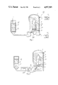
- FIG. 1 illustrates an embodiment of the invention in which high pressure air and a piston are used to pressurize the manufacturing apparatus according to the invention
- FIG. 2 is a second embodiment of the invention in which a positive displacement gear pump is used to pressurize the manufacturing apparatus according to the invention
- FIG . 3 is an embodiment of the invention in which a bell chamber and membrane are used to configure the manufacturing apparatus
- FIG. 4 is yet another embodiment of the invention.
- the high pressure lamination device 10 includes an outer high pressure tank 1 in which a tool 3 is mounted on a perforated support member 5 within the pressure tank 1 which is perforated to allow the passage of a polysilicone polymer 7 such as TX-750 or TX-875 polysilicone polymer manufactured by Dow Corning Corporation of Midland, Mich.
- a vacuum line 9 is connected to a vacuum pump 11 which evacuates the air from the chamber 1.
- a mechanical compression system shown as a positive displacement piston pump 13 is filled with the polysilicone polymer 7 in a displacement chamber 15 to which a positive pressure of approximately 50 psi is applied to the silicon polymer 7.
- the positive displacement piston pump 13 is used to compact the polysilicone polymer 7 to remove the voids in the polysilicone polymer 7 from the pressure tank 1 and the displacement chamber 15. At this pressure the granular polysilicone polymer binds together and the voids are eliminated, to create a quasi liquid state.
- the tool 3 has embedded on it a layer of staged prepreg 9 or thermoplastic prepreg such as F-74 manufactured by Hexcel Corporation or other Fiberglas or quartz gauze.
- the prepreg 9 is covered with a resin.
- the prepreg 9 is mounted to the mold 3 which through electrical controls includes a cartridge heater 17 for heating the mold 3 and prepreg 9 and thermocouples 19 for sensing the temperature of the mold 3 and therefore the prepreg 9.
- this pressure can be as low as 50 psi.
- This pressure is maintained during the curing process of the resin which can take up to 14 hours, after which time the pressure is reduced so that the polysilicone 7 reverts back to a granular material and the thermal plastic product which is manufactured by this process can be removed from the tool 3.
- the polymer is a relatively poor thermal conductor. Thus, relatively little heat is transmitted outward from the tool and through the chamber.
- the polysilicone polymer is pressurized through the use of a positive displacement gear pump 25 which during the initial pressurization a bypass valve 29 is open.
- This configuration allows the positive displacement piston pump 13 to pressurize the chamber 1 to 50 psi.
- the valve 29 is closed and the positive displacement gear pump continues to pressurize the chamber 1 according to the procedure discussed with regard to the embodiment of FIG. 1 until the pressure of approximately 3,000 psi is achieved.
- a relief valve 31 allows for circulation of the pressure from the chamber 1 through the pump 25 and back into the chamber to thus maintain the desired 3,000 psi.
- FIG. 3 The embodiment of FIG. 3 is based on the above noted thermal characteristics of the polysilicone polymer 7. Accordingly, a bell chamber 35 is utilized in conjunction with a flexible bag 37.
- the bag 37 is made of a material such as polysilicone, polyurethane or Buna-N, is mounted to a base plate 39 via bag seals 41.
- the polysilicone supply is provided from the positive displacement of piston pump 13 via the conduit 43 and the inside of the bell jar 35 is pressurized to 50 psi, turning the polysilicone polymer 7 into a liquid state.
- This process of course, as in the embodiment of FIG. 1, is implemented through the use of the vacuum 9.
- High pressure gas from the air pump 21 is then applied through the high pressure conduit 45 and flows in the space in between the flexible bag 35 and the bell chamber 35 pressurizing the polysilicone polymer 7 against the tool 3 during the curing process.
- FIG. 4 illustrates an embodiment similar to FIG. 3 in which the bag 37 is mounted within a high pressure chamber such as is shown in FIGS. 1 and 2 and thus is cured by the addition of heat to the mold 3 and pressure to the flexible bag 37. It should be noted that the separation between the high temperature mold and the thermoplastic bag as indicated by dimension lines 51 need only to be 3.5 inches. This is achievable because of the low thermal conductivity of the polysilicone polymer 7.
Landscapes
- Engineering & Computer Science (AREA)
- Mechanical Engineering (AREA)
- Chemical & Material Sciences (AREA)
- Composite Materials (AREA)
- Casting Or Compression Moulding Of Plastics Or The Like (AREA)
Abstract
Description
Claims (10)
Priority Applications (1)
| Application Number | Priority Date | Filing Date | Title |
|---|---|---|---|
| US07/300,750 US4957585A (en) | 1987-09-30 | 1989-01-23 | High pressure lamination chamber |
Applications Claiming Priority (2)
| Application Number | Priority Date | Filing Date | Title |
|---|---|---|---|
| US10308287A | 1987-09-30 | 1987-09-30 | |
| US07/300,750 US4957585A (en) | 1987-09-30 | 1989-01-23 | High pressure lamination chamber |
Related Parent Applications (1)
| Application Number | Title | Priority Date | Filing Date |
|---|---|---|---|
| US10308287A Continuation | 1987-09-30 | 1987-09-30 |
Publications (1)
| Publication Number | Publication Date |
|---|---|
| US4957585A true US4957585A (en) | 1990-09-18 |
Family
ID=26800073
Family Applications (1)
| Application Number | Title | Priority Date | Filing Date |
|---|---|---|---|
| US07/300,750 Expired - Fee Related US4957585A (en) | 1987-09-30 | 1989-01-23 | High pressure lamination chamber |
Country Status (1)
| Country | Link |
|---|---|
| US (1) | US4957585A (en) |
Cited By (11)
| Publication number | Priority date | Publication date | Assignee | Title |
|---|---|---|---|---|
| DE19717740A1 (en) * | 1997-04-26 | 1998-11-05 | Schoenberg & Cerny Gmbh | Plastic molded body with integrated optoelectronic lighting element |
| US20090053350A1 (en) * | 2007-08-24 | 2009-02-26 | Delta Pt, Llc | Pressure compensating molding system |
| EP2447029A2 (en) * | 2010-11-02 | 2012-05-02 | Honeywell International, Inc. | Apparatus and method for pitch impregnated preform densification |
| US20120104659A1 (en) * | 2010-11-02 | 2012-05-03 | Honeywell International Inc. | Apparatus for pitch densification |
| US9193113B2 (en) | 2010-12-17 | 2015-11-24 | Honeywell International Inc. | Apparatus for carbon fiber processing and pitch densification |
| US9944526B2 (en) | 2015-05-13 | 2018-04-17 | Honeywell International Inc. | Carbon fiber preforms |
| US10022890B2 (en) | 2015-09-15 | 2018-07-17 | Honeywell International Inc. | In situ carbonization of a resin to form a carbon-carbon composite |
| US10035305B2 (en) | 2015-06-30 | 2018-07-31 | Honeywell International Inc. | Method of making carbon fiber preforms |
| US10131113B2 (en) | 2015-05-13 | 2018-11-20 | Honeywell International Inc. | Multilayered carbon-carbon composite |
| US10300631B2 (en) | 2015-11-30 | 2019-05-28 | Honeywell International Inc. | Carbon fiber preforms |
| US10302163B2 (en) | 2015-05-13 | 2019-05-28 | Honeywell International Inc. | Carbon-carbon composite component with antioxidant coating |
Citations (6)
| Publication number | Priority date | Publication date | Assignee | Title |
|---|---|---|---|---|
| US2363933A (en) * | 1940-12-12 | 1944-11-28 | Langley Aviat Corp | Portable veneer press |
| US2423647A (en) * | 1943-07-14 | 1947-07-08 | Engineering & Res Corp | Method of making articles of compressed and impregnated wood |
| US3614811A (en) * | 1969-08-13 | 1971-10-26 | Shell Oil Co | Diaphragm-type form-shaping apparatus |
| US4334850A (en) * | 1978-07-31 | 1982-06-15 | Armen Garabedian | Apparatus for making a stress-free plastic article |
| US4418906A (en) * | 1981-10-28 | 1983-12-06 | Western Electric Company, Inc. | Sheet stock transfer apparatus |
| US4541891A (en) * | 1982-09-30 | 1985-09-17 | William C. Heller, Jr. | Method and apparatus for heat sealing plastic members |
-
1989
- 1989-01-23 US US07/300,750 patent/US4957585A/en not_active Expired - Fee Related
Patent Citations (6)
| Publication number | Priority date | Publication date | Assignee | Title |
|---|---|---|---|---|
| US2363933A (en) * | 1940-12-12 | 1944-11-28 | Langley Aviat Corp | Portable veneer press |
| US2423647A (en) * | 1943-07-14 | 1947-07-08 | Engineering & Res Corp | Method of making articles of compressed and impregnated wood |
| US3614811A (en) * | 1969-08-13 | 1971-10-26 | Shell Oil Co | Diaphragm-type form-shaping apparatus |
| US4334850A (en) * | 1978-07-31 | 1982-06-15 | Armen Garabedian | Apparatus for making a stress-free plastic article |
| US4418906A (en) * | 1981-10-28 | 1983-12-06 | Western Electric Company, Inc. | Sheet stock transfer apparatus |
| US4541891A (en) * | 1982-09-30 | 1985-09-17 | William C. Heller, Jr. | Method and apparatus for heat sealing plastic members |
Cited By (17)
| Publication number | Priority date | Publication date | Assignee | Title |
|---|---|---|---|---|
| DE19717740A1 (en) * | 1997-04-26 | 1998-11-05 | Schoenberg & Cerny Gmbh | Plastic molded body with integrated optoelectronic lighting element |
| DE19717740C2 (en) * | 1997-04-26 | 2001-07-05 | Schoenberg & Cerny Gmbh Wien | Plastic molded body with integrated optoelectronic light field and process for its production |
| US6411029B1 (en) | 1997-04-26 | 2002-06-25 | Schonberg + Cerny Gmbh | Plastic shaped body with an integrated optoelectronic luminous element |
| US20090053350A1 (en) * | 2007-08-24 | 2009-02-26 | Delta Pt, Llc | Pressure compensating molding system |
| US8033808B2 (en) * | 2007-08-24 | 2011-10-11 | Delta Pt, Llc | Pressure compensating molding system |
| US8721954B2 (en) | 2010-11-02 | 2014-05-13 | Honeywell International Inc. | Techniques for pitch densification |
| US20120104659A1 (en) * | 2010-11-02 | 2012-05-03 | Honeywell International Inc. | Apparatus for pitch densification |
| CN102529117A (en) * | 2010-11-02 | 2012-07-04 | 霍尼韦尔国际公司 | Apparatus for pitch densification |
| EP2447029A2 (en) * | 2010-11-02 | 2012-05-02 | Honeywell International, Inc. | Apparatus and method for pitch impregnated preform densification |
| CN102529117B (en) * | 2010-11-02 | 2016-01-20 | 霍尼韦尔国际公司 | For the device of pitch densification |
| US9193113B2 (en) | 2010-12-17 | 2015-11-24 | Honeywell International Inc. | Apparatus for carbon fiber processing and pitch densification |
| US9944526B2 (en) | 2015-05-13 | 2018-04-17 | Honeywell International Inc. | Carbon fiber preforms |
| US10131113B2 (en) | 2015-05-13 | 2018-11-20 | Honeywell International Inc. | Multilayered carbon-carbon composite |
| US10302163B2 (en) | 2015-05-13 | 2019-05-28 | Honeywell International Inc. | Carbon-carbon composite component with antioxidant coating |
| US10035305B2 (en) | 2015-06-30 | 2018-07-31 | Honeywell International Inc. | Method of making carbon fiber preforms |
| US10022890B2 (en) | 2015-09-15 | 2018-07-17 | Honeywell International Inc. | In situ carbonization of a resin to form a carbon-carbon composite |
| US10300631B2 (en) | 2015-11-30 | 2019-05-28 | Honeywell International Inc. | Carbon fiber preforms |
Similar Documents
| Publication | Publication Date | Title |
|---|---|---|
| EP0233134B1 (en) | Molding method and apparatus using a solid, flowable, polymer medium | |
| US4940563A (en) | Molding method and apparatus using a solid flowable, polymer medium | |
| US4957585A (en) | High pressure lamination chamber | |
| US5131834A (en) | Silicone gel isostatic pressurizing bag and method of use and manufacture | |
| CA1146457A (en) | Method of fabricating a composite structure | |
| US4704240A (en) | Method of fabricating tubular composite structures | |
| US6149844A (en) | Method of manufacturing composites | |
| US4148597A (en) | Apparatus and method for pressure molding composite structural parts | |
| US4816106A (en) | Method for the controlled curing of composites | |
| US4855011A (en) | Isostatic self-contained bond or mold tool | |
| US5009687A (en) | Method of molding a composite article using softened glass as a pressure transmitting medium | |
| EP0805746B1 (en) | Improved method of manufacturing composites | |
| US4828639A (en) | Elastomeric ball pressurizing method for adhesive bonding of assemblies | |
| GB2267457A (en) | Manufacture of components from composite material | |
| US4983345A (en) | Method of high temperature molding using a thermal barrier | |
| KR20220092400A (en) | Manufacturing Machine and Method for Carbon Fiber Composite Material Component | |
| JP2552879B2 (en) | Solid flowable particulate polymer | |
| KR950012845B1 (en) | Molding method using dual solid flowable polymer system | |
| FR2162296A1 (en) | Moulding resin impregnated fibres - using a mould lined with a flexible pressurised and heated bag | |
| EP0254901A2 (en) | Lamination method and apparatus | |
| JP3053275B2 (en) | Resin injection molding method | |
| US3541195A (en) | Method for molding insulation materials | |
| AU697678B2 (en) | Improved method of manufacturing composites | |
| US5073443A (en) | Thermal barrier for high temperature molding | |
| KEMP | Trapped rubber molding |
Legal Events
| Date | Code | Title | Description |
|---|---|---|---|
| FEPP | Fee payment procedure |
Free format text: PAYOR NUMBER ASSIGNED (ORIGINAL EVENT CODE: ASPN); ENTITY STATUS OF PATENT OWNER: LARGE ENTITY |
|
| FPAY | Fee payment |
Year of fee payment: 4 |
|
| FEPP | Fee payment procedure |
Free format text: PAYOR NUMBER ASSIGNED (ORIGINAL EVENT CODE: ASPN); ENTITY STATUS OF PATENT OWNER: LARGE ENTITY Free format text: PAYER NUMBER DE-ASSIGNED (ORIGINAL EVENT CODE: RMPN); ENTITY STATUS OF PATENT OWNER: LARGE ENTITY |
|
| AS | Assignment |
Owner name: RAYTHEON TI SYSTEMS, INC., TEXAS Free format text: ASSIGNMENT OF ASSIGNORS INTEREST;ASSIGNORS:TEXAS INSTRUMENTS INCORPORATED;TEXAS INSTRUMENTS DEUTSCHLAND GMBH;REEL/FRAME:008628/0414 Effective date: 19970711 |
|
| FPAY | Fee payment |
Year of fee payment: 8 |
|
| AS | Assignment |
Owner name: RAYTHEON COMPANY, A CORPORATION OF DELAWARE, MASSA Free format text: CHANGE OF NAME;ASSIGNOR:RAYTHEON TI SYSTEMS, INC.;REEL/FRAME:009875/0499 Effective date: 19981229 |
|
| REMI | Maintenance fee reminder mailed | ||
| LAPS | Lapse for failure to pay maintenance fees | ||
| STCH | Information on status: patent discontinuation |
Free format text: PATENT EXPIRED DUE TO NONPAYMENT OF MAINTENANCE FEES UNDER 37 CFR 1.362 |
|
| FP | Lapsed due to failure to pay maintenance fee |
Effective date: 20020918 |