US4954671A - Connectible switching device - Google Patents
Connectible switching device Download PDFInfo
- Publication number
- US4954671A US4954671A US07/323,347 US32334789A US4954671A US 4954671 A US4954671 A US 4954671A US 32334789 A US32334789 A US 32334789A US 4954671 A US4954671 A US 4954671A
- Authority
- US
- United States
- Prior art keywords
- coupling element
- jaw
- shaped coupling
- switching
- cone
- Prior art date
- Legal status (The legal status is an assumption and is not a legal conclusion. Google has not performed a legal analysis and makes no representation as to the accuracy of the status listed.)
- Expired - Lifetime
Links
- 230000008878 coupling Effects 0.000 claims abstract description 60
- 238000010168 coupling process Methods 0.000 claims abstract description 60
- 238000005859 coupling reaction Methods 0.000 claims abstract description 60
- 230000035515 penetration Effects 0.000 claims description 6
- 230000033001 locomotion Effects 0.000 claims description 3
- 230000005404 monopole Effects 0.000 description 2
- 230000005405 multipole Effects 0.000 description 2
- 238000010276 construction Methods 0.000 description 1
- 230000004048 modification Effects 0.000 description 1
- 238000012986 modification Methods 0.000 description 1
Images

Classifications
-
- H—ELECTRICITY
- H01—ELECTRIC ELEMENTS
- H01H—ELECTRIC SWITCHES; RELAYS; SELECTORS; EMERGENCY PROTECTIVE DEVICES
- H01H71/00—Details of the protective switches or relays covered by groups H01H73/00 - H01H83/00
- H01H71/10—Operating or release mechanisms
- H01H71/12—Automatic release mechanisms with or without manual release
- H01H71/46—Automatic release mechanisms with or without manual release having means for operating auxiliary contacts additional to the main contacts
- H01H71/462—Automatic release mechanisms with or without manual release having means for operating auxiliary contacts additional to the main contacts housed in a separate casing, juxtaposed to and having the same general contour as the main casing
-
- H—ELECTRICITY
- H01—ELECTRIC ELEMENTS
- H01H—ELECTRIC SWITCHES; RELAYS; SELECTORS; EMERGENCY PROTECTIVE DEVICES
- H01H71/00—Details of the protective switches or relays covered by groups H01H73/00 - H01H83/00
- H01H71/10—Operating or release mechanisms
- H01H71/1009—Interconnected mechanisms
- H01H71/1018—Interconnected mechanisms with only external interconnections
-
- Y—GENERAL TAGGING OF NEW TECHNOLOGICAL DEVELOPMENTS; GENERAL TAGGING OF CROSS-SECTIONAL TECHNOLOGIES SPANNING OVER SEVERAL SECTIONS OF THE IPC; TECHNICAL SUBJECTS COVERED BY FORMER USPC CROSS-REFERENCE ART COLLECTIONS [XRACs] AND DIGESTS
- Y10—TECHNICAL SUBJECTS COVERED BY FORMER USPC
- Y10S—TECHNICAL SUBJECTS COVERED BY FORMER USPC CROSS-REFERENCE ART COLLECTIONS [XRACs] AND DIGESTS
- Y10S200/00—Electricity: circuit makers and breakers
- Y10S200/06—Tie bar
Definitions
- the present invention relates to a switching device in a system of switching devices, which can be coupled to mountable switching, auxiliary switching, or signal switching devices.
- a multipole switch is constructed from a monopole circuit-breaker, whereby the actuating handles are interconnected with a busbar-type bridge.
- the handles have central recesses on their front sides, into which knobs engage with clearance in the longitudinal direction of the bridge.
- a switching device in a system of switching devices which can be coupled to mountable switching, auxiliary switching or signal devices, comprising a housing, a cylindrical, manually operated part disposed in the housing having a selector, a coupling element consisting of a pair, according to function, of a jaw-shaped and a cone-shaped coupling element constructed on the cylindrical part in the direction of the switching axis on a mounting side, with which the other coupling element of the function pair can be forced into engagement connection, wherein the jaw-like coupling element has a jaw tooth in engagement depth only for one coupling direction for a shallower penetration of a cone-like coupling element.
- a jaw-shaped coupling element can be arranged on the cylindrical part in the direction of the switching axis on a mounting side of the housing, for example, and works together with the cone-shaped coupling element in a housing slot on a surface of the housing, which engages from a device to be attached into the jaw-shaped coupling element on the mounting side of a target device.
- the jaw-shaped coupling element is designed only for one coupling direction with a jaw tooth or a jaw flank of the jaw-shaped coupling element in engagement depth.
- the cone-shaped coupling element of the switching device to be attached is designed just short enough, so that the jaw-shaped coupling element of a circuit-breaker, in the case of a provided second, shorter penetration depth, forms a jaw tooth only in the switch-on direction, then the switching device to be attached remains intact, when switching off manually. Thereby, one can easily fulfill the conditions that are required between signal circuit controllers and circuit-breakers of the error-signal circuit controller type.
- Such a signal circuit controller can only be switched on by the selector of the circuit-breaker, but can no longer be switched off by it.
- the signal circuit controller can only emit a signal, if the circuit-breaker has responded in automatic tripping action.
- a separate tripping coupling assures, in normal operation, that the signal circuit controller is switched off, only when there is an overload condition, whether it be an overcurrent or a short circuit of the circuit protected by the circuit-breaker.
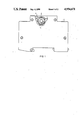
- FIG. 1 shows a connectible switching device, designed as a circuit-breaker, reproduced in its longitudinal direction, and with a part thereof shown in a cut-away view;
- FIG. 2 shows a manually operated part of the switching device of FIG. 1 reproduced in larger scale
- FIG. 3 shows a sectional view along line 3--3 of FIG. 2, together with a cone-shaped coupling element of an auxiliary switch to be attached;
- FIG. 4 shows a view of the representation of FIG. 3 rotated by 90°.
- the switching device 1 of FIG. 1 has a cylindrical, manually operated part 2 with a selector 3, which protrudes from a housing 5.1.
- a jaw-shaped coupling element 4 is arranged on the cylindrical part 2 in the direction of the switching axis on a mounting side, behind the drawing plane.
- the coupling element 4 is movable with its mounting behind a housing slot 5.
- a cone-shaped coupling element 6 of FIG. 3 is arranged in the housing slot on a surface. In one embodiment, the cone-shaped coupling element 6 engages deeply with the jaw-shaped coupling element 4.
- the cone-shaped coupling element 6 may be designed in two versions, a long version 6.1 and a short version 6.2.
- the cone-shaped coupling element engages between the jaw teeth 7 and 8.
- the teeth engaged are 7 and 8.1.
Landscapes
- Driving Mechanisms And Operating Circuits Of Arc-Extinguishing High-Tension Switches (AREA)
- Investigating Or Analyzing Materials By The Use Of Ultrasonic Waves (AREA)
- Excavating Of Shafts Or Tunnels (AREA)
- Magnetic Resonance Imaging Apparatus (AREA)
- Transmitters (AREA)
- Details Of Connecting Devices For Male And Female Coupling (AREA)
- Structure Of Receivers (AREA)
- Breakers (AREA)
- Friction Gearing (AREA)
- Massaging Devices (AREA)
- Switches With Compound Operations (AREA)
Abstract
A switching device in a system of switching devices, which can be coupled to mountable switching, auxiliary switching, or signal devices. In the case of a cylindrical, manually operated part, disposed in the housing, having a selector, a coupling element pair comprising a jaw-shaped coupling element and a cone-shaped coupling element are provided on the cylindrical part in the direction of the switching axis on a mounting side, the pair of coupling elements being movable behind a housing slot, and being forced in engagement connection with each other and arranged in a housing slot on the surface of a device to be attached.
Description
The present invention relates to a switching device in a system of switching devices, which can be coupled to mountable switching, auxiliary switching, or signal switching devices.
These types of switching devices are available on the market in many different model types. In a known switching device (German Pat. No. 25 40 745), a multipole switch is constructed from a monopole circuit-breaker, whereby the actuating handles are interconnected with a busbar-type bridge. To allow tolerances to be equalized during assembly, the handles have central recesses on their front sides, into which knobs engage with clearance in the longitudinal direction of the bridge. There are occasions, when one would like to do without these types of specially adapted bridge elements used specifically in the assembly.
It is an object of the present invention to provide a system of switching devices, whereby the switching devices are coupled without necessitating specifically prepared coupling elements.
The above and other objects of the invention are achieved by a switching device in a system of switching devices, which can be coupled to mountable switching, auxiliary switching or signal devices, comprising a housing, a cylindrical, manually operated part disposed in the housing having a selector, a coupling element consisting of a pair, according to function, of a jaw-shaped and a cone-shaped coupling element constructed on the cylindrical part in the direction of the switching axis on a mounting side, with which the other coupling element of the function pair can be forced into engagement connection, wherein the jaw-like coupling element has a jaw tooth in engagement depth only for one coupling direction for a shallower penetration of a cone-like coupling element.
A jaw-shaped coupling element can be arranged on the cylindrical part in the direction of the switching axis on a mounting side of the housing, for example, and works together with the cone-shaped coupling element in a housing slot on a surface of the housing, which engages from a device to be attached into the jaw-shaped coupling element on the mounting side of a target device.
According to a further embodiment, whereby the penetration of a cone-shaped coupling element is not as deep, the jaw-shaped coupling element is designed only for one coupling direction with a jaw tooth or a jaw flank of the jaw-shaped coupling element in engagement depth. Thus, with a long cone-shaped coupling element, a strong coupling of the manual-y operated parts can be attained for all the movements of a manually operated part, resulting from automatic tripping action, as well as hand operation. This type of coupling is desired, for example, between a circuit-breaker and an auxiliary switch to be attached. If the cone-shaped coupling element of the switching device to be attached is designed just short enough, so that the jaw-shaped coupling element of a circuit-breaker, in the case of a provided second, shorter penetration depth, forms a jaw tooth only in the switch-on direction, then the switching device to be attached remains intact, when switching off manually. Thereby, one can easily fulfill the conditions that are required between signal circuit controllers and circuit-breakers of the error-signal circuit controller type.
Such a signal circuit controller can only be switched on by the selector of the circuit-breaker, but can no longer be switched off by it. The signal circuit controller can only emit a signal, if the circuit-breaker has responded in automatic tripping action. In circuit-breakers of a monopole or multipole construction, a separate tripping coupling assures, in normal operation, that the signal circuit controller is switched off, only when there is an overload condition, whether it be an overcurrent or a short circuit of the circuit protected by the circuit-breaker.
The invention will be described in greater detail in the following detailed description with reference to the drawings, in which:
FIG. 1 shows a connectible switching device, designed as a circuit-breaker, reproduced in its longitudinal direction, and with a part thereof shown in a cut-away view;
FIG. 2 shows a manually operated part of the switching device of FIG. 1 reproduced in larger scale;
FIG. 3 shows a sectional view along line 3--3 of FIG. 2, together with a cone-shaped coupling element of an auxiliary switch to be attached; and
FIG. 4 shows a view of the representation of FIG. 3 rotated by 90°.
The switching device 1 of FIG. 1 has a cylindrical, manually operated part 2 with a selector 3, which protrudes from a housing 5.1. As shown in FIG. 3, a jaw-shaped coupling element 4 is arranged on the cylindrical part 2 in the direction of the switching axis on a mounting side, behind the drawing plane. The coupling element 4 is movable with its mounting behind a housing slot 5. A cone-shaped coupling element 6 of FIG. 3 is arranged in the housing slot on a surface. In one embodiment, the cone-shaped coupling element 6 engages deeply with the jaw-shaped coupling element 4. The cone-shaped coupling element 6 may be designed in two versions, a long version 6.1 and a short version 6.2. In the long version 6.1, the cone-shaped coupling element engages between the jaw teeth 7 and 8. With the long version of the coupling element 6.1, the teeth engaged are 7 and 8.1. Thus, a strong coupling is attained for all switch motions of the manually operated part of a circuit-breaker with this version.
If the short version 6.2 of the cone-shaped coupling element 6 is used, then only the flank of a single jaw tooth 8.2 is adjacent this penetration depth. On the other side of the coupling element 6, however, there is no adjacent jaw tooth 7. In the case of the jaw-shaped coupling element 4 reproduced in the exemplified embodiment, one attains, therefore, for a long cone-shaped coupling element 6.1, a coupling as is desired for auxiliary switches, and for a short cone-shaped coupling element 6.2, a coupling, as is desired for signal circuit controllers, which can be mounted on the circuit-breaker of FIG. 1 without requiring additional coupling elements for the manually operated part.
In the foregoing specification, the invention has been described with reference to a specific exemplary embodiment thereof It will, however, be evident that various modifications and changes may be made thereunto without departing from the broader spirit and scope of the invention as set forth in the appended claims The specification and drawings are, accordingly, to be regarded in an illustrative rather than in a restrictive sense.
Claims (2)
1. A switching device in a system having a plurality of switching devices, said switching device being coupled to mountable switching, auxiliary switching or signal devices, said switching device comprising a housing, a cylindrical, manually operated part disposed in the housing and having a switching axis, a manually operable selector attached to the cylindrical part, the cylindrical part having two coupling directions determined by movement of said selector, and further comprising a coupling element pair comprising a jaw-shaped coupling element and a cone-shaped coupling element, one of said jaw-shaped coupling element and cone-shaped coupling element being disposed on the cylindrical part in the direction of the switching axis, the jaw-shaped and cone-shaped coupling elements being in engagement, the jaw-shaped coupling element having a jaw tooth, said jaw tooth being in engagement depth only for one coupling direction of the cylindrical part at a shallow penetration by the cone-shaped coupling element into the jaw-shaped coupling element and said jaw tooth being in engagement depth for both coupling directions at a deep penetration by the cone-shaped coupling element into the jaw-shaped coupling element.
2. The switching device recited in claim 1, wherein the jaw-shaped coupling element is arranged on the cylindrical part in the direction of the switching axis on a mounting side, is movable behind a housing slot and engageable with the cone-shaped coupling element in a housing slot on a surface of the housing, the cone-shaped coupling element extending from a device to be attached to the jaw-shaped coupling element.
Applications Claiming Priority (2)
| Application Number | Priority Date | Filing Date | Title |
|---|---|---|---|
| DE3808472 | 1988-03-14 | ||
| DE3808472 | 1988-03-14 |
Publications (1)
| Publication Number | Publication Date |
|---|---|
| US4954671A true US4954671A (en) | 1990-09-04 |
Family
ID=6349695
Family Applications (1)
| Application Number | Title | Priority Date | Filing Date |
|---|---|---|---|
| US07/323,347 Expired - Lifetime US4954671A (en) | 1988-03-14 | 1989-03-14 | Connectible switching device |
Country Status (8)
| Country | Link |
|---|---|
| US (1) | US4954671A (en) |
| EP (1) | EP0332936B1 (en) |
| AT (1) | ATE106603T1 (en) |
| AU (1) | AU616738B2 (en) |
| BR (1) | BR8901158A (en) |
| DE (2) | DE8816387U1 (en) |
| ES (1) | ES2053832T3 (en) |
| ZA (1) | ZA891876B (en) |
Citations (5)
| Publication number | Priority date | Publication date | Assignee | Title |
|---|---|---|---|---|
| US2824191A (en) * | 1953-02-05 | 1958-02-18 | Fed Electric Prod Co | Circuit breakers |
| DE1044937B (en) * | 1956-11-27 | 1958-11-27 | Elektro App Werke J W Stalin V | Coupling arrangement for two single-pole circuit-breakers or switching mechanisms for circuit-breakers, in particular small circuit-breakers, to achieve a two-pole switching system, arranged side by side, operated via a common switching lever and provided with toggle lever locking |
| DE1286620B (en) * | 1962-03-26 | 1969-01-09 | Licentia Gmbh | Switching mechanism for automatic switch |
| US3464045A (en) * | 1967-05-11 | 1969-08-26 | Gen Electric | Circuit breaker selective trip mechanism |
| US4385214A (en) * | 1981-08-14 | 1983-05-24 | Square D Company | Interlock pushbutton assembly |
Family Cites Families (1)
| Publication number | Priority date | Publication date | Assignee | Title |
|---|---|---|---|---|
| FR2615322B1 (en) * | 1987-05-11 | 1989-06-30 | Merlin Gerin | TRIP BAR OF A MULTIPOLAR CIRCUIT BREAKER ASSOCIATED WITH AN AUXILIARY TRIGGER BLOCK |
-
1988
- 1988-03-14 DE DE8816387U patent/DE8816387U1/en not_active Expired
-
1989
- 1989-03-01 EP EP89103582A patent/EP0332936B1/en not_active Expired - Lifetime
- 1989-03-01 ES ES89103582T patent/ES2053832T3/en not_active Expired - Lifetime
- 1989-03-01 DE DE58907726T patent/DE58907726D1/en not_active Expired - Fee Related
- 1989-03-01 AT AT89103582T patent/ATE106603T1/en not_active IP Right Cessation
- 1989-03-10 AU AU31203/89A patent/AU616738B2/en not_active Ceased
- 1989-03-13 BR BR898901158A patent/BR8901158A/en not_active IP Right Cessation
- 1989-03-13 ZA ZA891876A patent/ZA891876B/en unknown
- 1989-03-14 US US07/323,347 patent/US4954671A/en not_active Expired - Lifetime
Patent Citations (5)
| Publication number | Priority date | Publication date | Assignee | Title |
|---|---|---|---|---|
| US2824191A (en) * | 1953-02-05 | 1958-02-18 | Fed Electric Prod Co | Circuit breakers |
| DE1044937B (en) * | 1956-11-27 | 1958-11-27 | Elektro App Werke J W Stalin V | Coupling arrangement for two single-pole circuit-breakers or switching mechanisms for circuit-breakers, in particular small circuit-breakers, to achieve a two-pole switching system, arranged side by side, operated via a common switching lever and provided with toggle lever locking |
| DE1286620B (en) * | 1962-03-26 | 1969-01-09 | Licentia Gmbh | Switching mechanism for automatic switch |
| US3464045A (en) * | 1967-05-11 | 1969-08-26 | Gen Electric | Circuit breaker selective trip mechanism |
| US4385214A (en) * | 1981-08-14 | 1983-05-24 | Square D Company | Interlock pushbutton assembly |
Also Published As
| Publication number | Publication date |
|---|---|
| DE8816387U1 (en) | 1989-06-08 |
| BR8901158A (en) | 1989-10-31 |
| ATE106603T1 (en) | 1994-06-15 |
| EP0332936A1 (en) | 1989-09-20 |
| AU3120389A (en) | 1989-09-14 |
| ZA891876B (en) | 1989-10-25 |
| ES2053832T3 (en) | 1994-08-01 |
| AU616738B2 (en) | 1991-11-07 |
| EP0332936B1 (en) | 1994-06-01 |
| DE58907726D1 (en) | 1994-07-07 |
Similar Documents
| Publication | Publication Date | Title |
|---|---|---|
| US5343007A (en) | Rocker switch | |
| DE3875376D1 (en) | RELEASE CLUTCH LEVER FOR A MULTIPOLAR CIRCUIT BREAKER BLOCK INTERACTING WITH A TRIP BLOCK. | |
| EP1039499A3 (en) | Circuit breaker handle block | |
| AU3726689A (en) | A rubber stop assembly for a multipole circuit breaker | |
| EP0018133B1 (en) | Electrical switch with several selectors | |
| CA2292470A1 (en) | Multiple microswitch actuation mechanism | |
| EP0362871A3 (en) | Remote-controlled circuit breaker | |
| EP0367102A3 (en) | Short circuit indicator | |
| MXPA01011395A (en) | Multi-function stalk switch. | |
| EP0362845A3 (en) | Remote-controlled circuit breaker | |
| EP0362846A3 (en) | Remote-controlled circuit breaker | |
| HK97487A (en) | Multiple switch using a rotary actuator | |
| US6160227A (en) | Toggle switch stop | |
| CA2235878A1 (en) | Switch connector | |
| US4954671A (en) | Connectible switching device | |
| US7019240B2 (en) | Electrical switching apparatus interface assembly and operating handle attachment therefor | |
| DE69930331D1 (en) | Switching off an electrically controlled brake system by switching off the ignition switch with a delay time | |
| GB1447780A (en) | Elecgrical circuit breakers | |
| EP0364950A3 (en) | Remote-controlled circuit breaker | |
| CA2286228A1 (en) | Electrical switch | |
| EP0745914B1 (en) | Multifunctional timer | |
| CA2207562A1 (en) | Multi-functional electrical switch assembly with momentary operating mechanism | |
| EP0777244A3 (en) | A lock-on, lock-off switch | |
| AU5733499A (en) | Coupling device | |
| KR100191171B1 (en) | Multifunction button |
Legal Events
| Date | Code | Title | Description |
|---|---|---|---|
| AS | Assignment |
Owner name: SIEMENS AKTIENGESELLSCHAFT, ORGANIZED UNDER THE FE Free format text: ASSIGNMENT OF ASSIGNORS INTEREST.;ASSIGNOR:SCHMIDT, HANS;REEL/FRAME:005074/0188 Effective date: 19890427 |
|
| STCF | Information on status: patent grant |
Free format text: PATENTED CASE |
|
| FEPP | Fee payment procedure |
Free format text: PAYOR NUMBER ASSIGNED (ORIGINAL EVENT CODE: ASPN); ENTITY STATUS OF PATENT OWNER: LARGE ENTITY |
|
| FPAY | Fee payment |
Year of fee payment: 4 |
|
| FPAY | Fee payment |
Year of fee payment: 8 |
|
| FPAY | Fee payment |
Year of fee payment: 12 |