US4945295A - Operation confirmatory circuit for linear actuator - Google Patents
Operation confirmatory circuit for linear actuator Download PDFInfo
- Publication number
- US4945295A US4945295A US07/253,198 US25319888A US4945295A US 4945295 A US4945295 A US 4945295A US 25319888 A US25319888 A US 25319888A US 4945295 A US4945295 A US 4945295A
- Authority
- US
- United States
- Prior art keywords
- switch
- actuator
- switches
- rod
- motor
- Prior art date
- Legal status (The legal status is an assumption and is not a legal conclusion. Google has not performed a legal analysis and makes no representation as to the accuracy of the status listed.)
- Expired - Fee Related
Links
Images


Classifications
-
- H—ELECTRICITY
- H02—GENERATION; CONVERSION OR DISTRIBUTION OF ELECTRIC POWER
- H02P—CONTROL OR REGULATION OF ELECTRIC MOTORS, ELECTRIC GENERATORS OR DYNAMO-ELECTRIC CONVERTERS; CONTROLLING TRANSFORMERS, REACTORS OR CHOKE COILS
- H02P7/00—Arrangements for regulating or controlling the speed or torque of electric DC motors
- H02P7/03—Arrangements for regulating or controlling the speed or torque of electric DC motors for controlling the direction of rotation of DC motors
Definitions
- This invention relates to an operation confirmatory circuit for a linear actuator, and more particularly to a circuit for verifying that an intended operation has been executed by a linear actuator capable of positioning an object by means of an electric motor.
- Linear actuators are used to transform rotation of a motor into linear motion of rod operating mechanisms such as gears, screw shafts, nuts, etc.
- rod operating mechanisms such as gears, screw shafts, nuts, etc.
- a ball screw mechanism is commonly used.
- Linear actuators usually require electrical switching in order to be operative. Unlike conventional mechanisms utilizing cables, links and the like, which encounter problems such as troublesome mounting and inoperativeness due to freezing or rust, linear actuators are especially preferred for manipulating devices such as valves, clutches, and engine throttles. However, since actuator positioning is performed by mechanical force, an operator is unable to "feel" whether or not the actual positioning took place. Therefore, it is necessary to provide some means for confirming that the operation has occurred. Many of the devices in the prior art are unreliable and provide false verifications.
- the present invention solves the above-mentioned problem with an operation confirmatory circuit which signals an operator when an operating rod, linearly driven by an electric motor, has reached either of its end positions.
- the circuit includes first and second switches connected in series with first and second diodes connected across each switch and connected to each other in opposition. The first switch opens when the rod is near one end position, and the second switch opens when the rod is near the other end position.
- a lamp in series with a third switch which is connected in parallel with a third diode, permits electric current to energize the lamp when the rod moves to the one end position.
- the rod continues to advance in the opposite direction, and when it has moved a predetermined distance, the second switch opens, causing the lamp to be extinguished. As a result, the operator is notified that the rod has been restored to the original condition.
- the lamp is lit as the rod approaches the one end position but it will remain lit after the rod begins to leave the one end position. It is extinguished only after the rod has moved the predetermined distance.
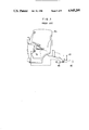
- FIG. 1 diagrammatically shows how a linear actuator of the prior art is applied in an automotive body
- FIG. 2 is an elevation of the linear actuator of FIG. 1;
- FIG. 3 is a prior art circuit as applied to the linear actuator in FIG. 2;
- FIG. 4 is a circuit of one embodiment of a linear actuator according to the present invention.
- FIG. 5 is an elevation of the linear actuator of FIG. 4;
- FIG. 6 is a partial section of the linear actuator of FIG. 5.
- FIG. 7 is a circuit of another embodiment according to the invention.
- FIG. 1 a conventional linear actuator 60, in solid outline, mounted on an automotive body 64 for operating a change-over or transfer mechanism 65 such as a clutch or gear train.
- a change-over or transfer mechanism 65 such as a clutch or gear train.
- actuator 60 is controlled by an electrical circuit 66 which includes a pair of reed switches 68a, 68b at the both ends of a cylinder 62 operated by a magnet 67 mounted on the rod 63, and confirmation lamps 69a, 69b near the operator (driver) in body 64.
- switch 70 With switch 70 in the position shown in FIG. 3, power is supplied of one polarity to motor 61 to drive rod 63 to the right in FIG. 2.
- magnet 67 closes the reed switch 68a to light the lamp 69a notifying the operator that the change-over of mechanism 65 has occurred.
- switch 70 is switched reversing the polarity of the current to the motor 61 causing it to rotate in the reverse direction so that the rod 63 retracts.
- Lamp 69a will be extinguished as result of a minimal backward movement of the rod 63 even though mechanism 65 has not been fully restored to its original condition. No indication is given to the operator that mechanism 65 has reached its original condition. Consequently, the operator prematurely stop the linear actuator 60.
- the linear actuator 60 is modified as shown by the dotted line in FIGS. 1, 2 and 3 with a reed switch 68b and a lamp 69b utilized instead of switch 68a and lamp 69a. In this case as well, there is a likelihood of misleading indication of the lamp as explained above.
- the conventional confirmatory circuit 66 has a drawback that it may give a misleading indication about the state of the mechanism to be operated by means of a linear actuator.
- automatic-return switches 72a, 72b and two diodes 73a, 73b in FIG. 3 constitute an automatic stop circuit 74 for automatically stopping the motor 61 by detecting over-load working on the rod 63 at the both end positions.
- a linear actuator A according to the invention includes an operating rod 15 which is linearly moved by means of an electric motor 16.
- the rod 15 is adapted to automatically stop when it reaches the forward and rear end positions as well as when an over-load is detected.
- a cylindrical larger bore 2 and a smaller bore 3 are coaxially provided; and in the forward position an outer cylinder 4 is mounted; and in the rear position, a cover 6 is secured to a flange 5.
- two cup-shaped spring receivers 7, 8 are slidably inserted in a face-to-face relationship; and at the bottom portions of each of said cup shapes, bearings 9, 9 are provided to support the distal end 11 of a screw shaft 10.
- a compression coil spring 13 is held with a predetermined pre-loading such that the front receiver 7 abuts against a stepped portion of the bore 3, and the rear receiver 8 abuts against a stop ring 12.
- a nut 14 is threadedly engaged with the screw shaft 10, to which the operating rod 15 is secured.
- the rod 15 is connected to a mechanism such as mechanism 65 in FIG. 1 and is prevented from rotating with screw shaft 15.
- the distal end 11 and the output shaft 17 of the motor 16 are connected by a gear train 18, 19 and 20.
- a switch box 23 within a case 21 is fixed at an aperture 22 in the body 1 and contains automatic-return type switches 24, 25.
- Respective operating members 26, 26' of said switches normally project upward to operate the respective switches when pushed downward by the tapered surfaces 27, 27' at the opposing ends of the spring receivers 7, 8.
- Lead wires 29 and 30 connect to motor 16, and wires 31, 32 to power supply lines.
- an automatic stop circuit B of the operating rod which includes switches 24, 25 connected in series with an armature 33 of the motor 16.
- Diodes 34, 35 are each connected across the respective switches 24, 25 in anode-to-anode opposition.
- a change-over switch 37 is connected to a direct current power source 36 to change the polarity thereof.
- An operation confirmatory circuit C which includes a lamp 39 and a reed switch 38 connected in series with one of the switches 37 and a point between the two switches 24, 25.
- the reed switch 38 is proximate to the forward end of the cylinder 4 and is closed or opened by means of a magnet 40 provided on the nut 14.
- the switch 38 is adapted to latch closed after the rod 15 has fully reached the end position.
- a diode 41 is connected across the switch 38 with its anode connected in opposition to the anodes of the switches 24, 25.
- the circuits B and C function as follows.
- the rod 15 moves to the right in FIG. 6.
- a thrust load received by the rod 15 is transmitted to the spring 13 through the spring receiver 7.
- the spring receiver 7 is urged to the left in FIG. 6 and tapered surface 27 of the spring receiver 7 pushes the operating member 26 downward to open the switch 24. Consequently, the motor 16 and rod 15 stop as the power is disconnected.
- the switch 24 remains open.
- the magnet 40 also advances along with the rod 15 and closes the reed switch 38 to light the lamp 39.
- the operator is informed when the change-over of the mechanism 65 has been achieved.
- a first change-over is effected when the rod 15 reaches the forward end position; namely, in the pushing direction of the rod 15.
- the embodiment in FIG. 7 effects the first change-over when the rod 15 reaches the backward end position; namely, in the pulling direction of the rod 15.
- an automatic stop circuit D which includes automatic-return type switches 50, 51 connected in series with the armature 33 of the motor 16.
- Diodes 52, 53 are each connected across the respective switches 50, 51 in cathode-to-cathode opposition.
- a switch 55 is connected to a power source 54 so that the polarity of the power may be changed.
- the operation confirmatory circuit E is similar to the embodiment of FIG. 4.
- a reed switch 56, a lamp 57 and a diode 58 are connected in series with the switch 55 and at a point between the switches 50, 51.
- the switch 56 which is located proximate to the rearward end position of the rod 15, as shown by the phantom line in FIG. 5, is opened and closed by the magnet 40 on the nut 14.
- FIG. 7 functions as follows.
- the rod 15 moves to the left in FIG. 6.
- a thrust load received by the rod 15 is transmitted to the spring 13 through the spring receiver 7; and when the load exceeds a pre-determined pre-load of the spring 13, the spring receiver 8 moves to the right in FIG. 6 and causes the tapered surface 27' of the spring receiver 8 to push the operating member 26' downward to open the switch 50. Consequently, the motor 16, and the rod 15 stop as the power is disconnected. In that state, the nut 14 cannot retract with the pressure of the spring 13 and the switch 50 remains open.
- the magnet 40 also moves along with the rod 15 and closes the reed switch 56 and the lamp 57 is lit. Thus, the operator is informed when the change-over of the mechanism 65 has been achieved.
- either of the lamps 39 and 57 may be lit when the rod has reached the forward or rearward end position; however, it is not put out immediately when the rod starts to move in the opposite direction.
- the lamp is put out only when the rod has reached the opposite end position. This means that when a first switch-over of a mechanism is to be effected, the lamp is lit almost simultaneously with the switch-over action.
- the lamp is put out when the rod has reached the opposite end position after restoring the mechanism 65 to its original condition.
- the confirmatory circuit also functions as an automatic stop circuit, the whole circuit may be simple, requiring a smaller number of component parts.
Landscapes
- Engineering & Computer Science (AREA)
- Power Engineering (AREA)
- Connection Of Motors, Electrical Generators, Mechanical Devices, And The Like (AREA)
- Control Of Position Or Direction (AREA)
Abstract
Description
Claims (6)
Applications Claiming Priority (2)
| Application Number | Priority Date | Filing Date | Title |
|---|---|---|---|
| JP62303203A JPH01145706A (en) | 1987-12-02 | 1987-12-02 | Actuation confirming circuit for motor-driven cylinder |
| JP62-303203 | 1987-12-02 |
Publications (1)
| Publication Number | Publication Date |
|---|---|
| US4945295A true US4945295A (en) | 1990-07-31 |
Family
ID=17918123
Family Applications (1)
| Application Number | Title | Priority Date | Filing Date |
|---|---|---|---|
| US07/253,198 Expired - Fee Related US4945295A (en) | 1987-12-02 | 1988-10-04 | Operation confirmatory circuit for linear actuator |
Country Status (2)
| Country | Link |
|---|---|
| US (1) | US4945295A (en) |
| JP (1) | JPH01145706A (en) |
Cited By (1)
| Publication number | Priority date | Publication date | Assignee | Title |
|---|---|---|---|---|
| US20030089683A1 (en) * | 2000-02-03 | 2003-05-15 | Per-Olof Thuresson | Circuit breaker |
Citations (7)
| Publication number | Priority date | Publication date | Assignee | Title |
|---|---|---|---|---|
| US3198907A (en) * | 1960-11-14 | 1965-08-03 | Gen Electric | Electrically operated circuit breaker |
| US3896363A (en) * | 1974-03-18 | 1975-07-22 | Cincinnati Milacron Inc | Feedback circuit for detecting the failure of a stepping motor to respond to the control circuit |
| US3905435A (en) * | 1974-06-17 | 1975-09-16 | Telesforo G Coronado | Signaling system for use on automotive vehicles |
| US3909692A (en) * | 1973-02-07 | 1975-09-30 | Krupp Gmbh | Measuring instrument control |
| US3909691A (en) * | 1973-01-29 | 1975-09-30 | Rca Corp | Direction indicating display system |
| US4763219A (en) * | 1986-11-14 | 1988-08-09 | Tsubakimoto Chain Co. | Overload protection for DC motor-driven linear actuator |
| US4766413A (en) * | 1987-04-01 | 1988-08-23 | School Bus Parts Co. Of Canada Inc. | School bus stop sign control apparatus |
-
1987
- 1987-12-02 JP JP62303203A patent/JPH01145706A/en active Pending
-
1988
- 1988-10-04 US US07/253,198 patent/US4945295A/en not_active Expired - Fee Related
Patent Citations (7)
| Publication number | Priority date | Publication date | Assignee | Title |
|---|---|---|---|---|
| US3198907A (en) * | 1960-11-14 | 1965-08-03 | Gen Electric | Electrically operated circuit breaker |
| US3909691A (en) * | 1973-01-29 | 1975-09-30 | Rca Corp | Direction indicating display system |
| US3909692A (en) * | 1973-02-07 | 1975-09-30 | Krupp Gmbh | Measuring instrument control |
| US3896363A (en) * | 1974-03-18 | 1975-07-22 | Cincinnati Milacron Inc | Feedback circuit for detecting the failure of a stepping motor to respond to the control circuit |
| US3905435A (en) * | 1974-06-17 | 1975-09-16 | Telesforo G Coronado | Signaling system for use on automotive vehicles |
| US4763219A (en) * | 1986-11-14 | 1988-08-09 | Tsubakimoto Chain Co. | Overload protection for DC motor-driven linear actuator |
| US4766413A (en) * | 1987-04-01 | 1988-08-23 | School Bus Parts Co. Of Canada Inc. | School bus stop sign control apparatus |
Cited By (1)
| Publication number | Priority date | Publication date | Assignee | Title |
|---|---|---|---|---|
| US20030089683A1 (en) * | 2000-02-03 | 2003-05-15 | Per-Olof Thuresson | Circuit breaker |
Also Published As
| Publication number | Publication date |
|---|---|
| JPH01145706A (en) | 1989-06-07 |
Similar Documents
| Publication | Publication Date | Title |
|---|---|---|
| US4763219A (en) | Overload protection for DC motor-driven linear actuator | |
| US5990649A (en) | Control device for quick angle adjustment of rearview mirror | |
| US3927436A (en) | Multiple-shaft double-motion drive mechanism | |
| US4910419A (en) | Overload detection mechanism for motor-driven linear actuator | |
| EP0064602A2 (en) | Automatic door locking/unlocking device for an automotive vehicle | |
| DE69100216D1 (en) | OPERATING DEVICE FOR AN AUTOMATIC MOTOR VEHICLE TRANSMISSION. | |
| GB2292231A (en) | Electric rearview mirror control system | |
| EP0883150A3 (en) | Electrical circuit breaker with manual and remote actuators | |
| JPH05203048A (en) | Electric control type shift actuator | |
| US5915668A (en) | Fail safe valve actuator | |
| EP0362871A3 (en) | Remote-controlled circuit breaker | |
| US5235260A (en) | Wiper controller | |
| US4945295A (en) | Operation confirmatory circuit for linear actuator | |
| US5083103A (en) | Energy management accessory for circuit breaker | |
| US4106072A (en) | Control switch relay and control circuit means | |
| US4999550A (en) | Automatic rear wiper control | |
| EP0989033A3 (en) | Battery disconnection system | |
| US5099703A (en) | Inertia drive engine starter | |
| US4323827A (en) | Apparatus for controlling a two-speed shift motor | |
| US2964601A (en) | Electrically operated marine engine gear shift | |
| US5237248A (en) | Control circuit having double-pole double-throw switching device for electrically powered tool | |
| US4133020A (en) | Control switch relay and control circuit means | |
| US4639839A (en) | Vehicular lighting device having a power driven lamp cover | |
| WO1999016585A1 (en) | Power nutrunner with shut-off | |
| US4196992A (en) | Camera film winding and shutter release mechanism |
Legal Events
| Date | Code | Title | Description |
|---|---|---|---|
| AS | Assignment |
Owner name: TSUBAKIMOTO CHAIN COMPANY, 17-88, TSURUMI 4-CHOME, Free format text: ASSIGNMENT OF ASSIGNORS INTEREST.;ASSIGNORS:HARA, FUMIHIKO;HAYASHI, SHUJI;YAMADA, GENJIRO;REEL/FRAME:004974/0175 Effective date: 19880921 Owner name: KABUSHIKI KAISHA NIKKEN, 35-36, TORIISHI 2-CHOME, Free format text: ASSIGNMENT OF ASSIGNORS INTEREST.;ASSIGNORS:HARA, FUMIHIKO;HAYASHI, SHUJI;YAMADA, GENJIRO;REEL/FRAME:004974/0175 Effective date: 19880921 Owner name: TSUBAKIMOTO CHAIN COMPANY, A CORP. OF JAPAN, JAPAN Free format text: ASSIGNMENT OF ASSIGNORS INTEREST;ASSIGNORS:HARA, FUMIHIKO;HAYASHI, SHUJI;YAMADA, GENJIRO;REEL/FRAME:004974/0175 Effective date: 19880921 Owner name: KABUSHIKI KAISHA NIKKEN, A CORP. OF JAPAN, JAPAN Free format text: ASSIGNMENT OF ASSIGNORS INTEREST;ASSIGNORS:HARA, FUMIHIKO;HAYASHI, SHUJI;YAMADA, GENJIRO;REEL/FRAME:004974/0175 Effective date: 19880921 |
|
| REMI | Maintenance fee reminder mailed | ||
| LAPS | Lapse for failure to pay maintenance fees | ||
| FP | Lapsed due to failure to pay maintenance fee |
Effective date: 19940803 |
|
| STCH | Information on status: patent discontinuation |
Free format text: PATENT EXPIRED DUE TO NONPAYMENT OF MAINTENANCE FEES UNDER 37 CFR 1.362 |