US4934595A - Method and aparatus for spray coating - Google Patents
Method and aparatus for spray coating Download PDFInfo
- Publication number
- US4934595A US4934595A US07/234,178 US23417888A US4934595A US 4934595 A US4934595 A US 4934595A US 23417888 A US23417888 A US 23417888A US 4934595 A US4934595 A US 4934595A
- Authority
- US
- United States
- Prior art keywords
- disposed
- particulate material
- bore
- annular
- body member
- Prior art date
- Legal status (The legal status is an assumption and is not a legal conclusion. Google has not performed a legal analysis and makes no representation as to the accuracy of the status listed.)
- Expired - Lifetime
Links
- 238000000034 method Methods 0.000 title claims abstract description 17
- 238000005507 spraying Methods 0.000 title claims abstract description 13
- 239000011236 particulate material Substances 0.000 claims abstract description 105
- 239000007921 spray Substances 0.000 claims abstract description 81
- 238000002485 combustion reaction Methods 0.000 claims abstract description 32
- 230000007246 mechanism Effects 0.000 claims abstract description 13
- 238000002156 mixing Methods 0.000 claims abstract description 10
- 239000000463 material Substances 0.000 claims description 51
- 238000002844 melting Methods 0.000 claims description 14
- 230000008018 melting Effects 0.000 claims description 14
- 239000000203 mixture Substances 0.000 claims description 12
- 239000002245 particle Substances 0.000 claims description 12
- 230000001105 regulatory effect Effects 0.000 claims description 11
- 230000013011 mating Effects 0.000 claims description 7
- 238000004891 communication Methods 0.000 claims description 6
- 125000006850 spacer group Chemical group 0.000 claims description 5
- 238000003780 insertion Methods 0.000 claims description 3
- 230000037431 insertion Effects 0.000 claims description 3
- 238000007789 sealing Methods 0.000 claims description 3
- 238000010438 heat treatment Methods 0.000 claims 1
- 239000011248 coating agent Substances 0.000 abstract description 5
- 238000000576 coating method Methods 0.000 abstract description 5
- 230000002708 enhancing effect Effects 0.000 abstract 1
- 239000002737 fuel gas Substances 0.000 abstract 1
- 239000007789 gas Substances 0.000 description 40
- 239000012815 thermoplastic material Substances 0.000 description 17
- ATUOYWHBWRKTHZ-UHFFFAOYSA-N Propane Chemical compound CCC ATUOYWHBWRKTHZ-UHFFFAOYSA-N 0.000 description 12
- 230000009471 action Effects 0.000 description 6
- 239000001294 propane Substances 0.000 description 6
- 239000000654 additive Substances 0.000 description 5
- 229920001169 thermoplastic Polymers 0.000 description 5
- 239000004416 thermosoftening plastic Substances 0.000 description 5
- 239000004033 plastic Substances 0.000 description 4
- 229920003023 plastic Polymers 0.000 description 4
- 238000010276 construction Methods 0.000 description 3
- 238000010586 diagram Methods 0.000 description 3
- 239000012530 fluid Substances 0.000 description 3
- 229920003298 Nucrel® Polymers 0.000 description 2
- 239000004698 Polyethylene Substances 0.000 description 2
- 229920003182 Surlyn® Polymers 0.000 description 2
- 230000000996 additive effect Effects 0.000 description 2
- 239000003570 air Substances 0.000 description 2
- 230000002950 deficient Effects 0.000 description 2
- 238000013461 design Methods 0.000 description 2
- 230000000694 effects Effects 0.000 description 2
- 230000005484 gravity Effects 0.000 description 2
- 239000013618 particulate matter Substances 0.000 description 2
- -1 polyethylene Polymers 0.000 description 2
- 229920000573 polyethylene Polymers 0.000 description 2
- 229920003345 Elvax® Polymers 0.000 description 1
- 239000004677 Nylon Substances 0.000 description 1
- 229910000831 Steel Inorganic materials 0.000 description 1
- 239000012963 UV stabilizer Substances 0.000 description 1
- 230000002411 adverse Effects 0.000 description 1
- 239000000567 combustion gas Substances 0.000 description 1
- 239000012612 commercial material Substances 0.000 description 1
- 229920001971 elastomer Polymers 0.000 description 1
- 239000000806 elastomer Substances 0.000 description 1
- 239000004615 ingredient Substances 0.000 description 1
- 238000012986 modification Methods 0.000 description 1
- 230000004048 modification Effects 0.000 description 1
- 239000012768 molten material Substances 0.000 description 1
- 229920001778 nylon Polymers 0.000 description 1
- 230000008569 process Effects 0.000 description 1
- 230000009467 reduction Effects 0.000 description 1
- 239000011369 resultant mixture Substances 0.000 description 1
- 238000012552 review Methods 0.000 description 1
- 239000010959 steel Substances 0.000 description 1
- 239000000454 talc Substances 0.000 description 1
- 229910052623 talc Inorganic materials 0.000 description 1
Images


Classifications
-
- B—PERFORMING OPERATIONS; TRANSPORTING
- B05—SPRAYING OR ATOMISING IN GENERAL; APPLYING FLUENT MATERIALS TO SURFACES, IN GENERAL
- B05B—SPRAYING APPARATUS; ATOMISING APPARATUS; NOZZLES
- B05B7/00—Spraying apparatus for discharge of liquids or other fluent materials from two or more sources, e.g. of liquid and air, of powder and gas
- B05B7/16—Spraying apparatus for discharge of liquids or other fluent materials from two or more sources, e.g. of liquid and air, of powder and gas incorporating means for heating or cooling the material to be sprayed
- B05B7/20—Spraying apparatus for discharge of liquids or other fluent materials from two or more sources, e.g. of liquid and air, of powder and gas incorporating means for heating or cooling the material to be sprayed by flame or combustion
- B05B7/201—Spraying apparatus for discharge of liquids or other fluent materials from two or more sources, e.g. of liquid and air, of powder and gas incorporating means for heating or cooling the material to be sprayed by flame or combustion downstream of the nozzle
- B05B7/205—Spraying apparatus for discharge of liquids or other fluent materials from two or more sources, e.g. of liquid and air, of powder and gas incorporating means for heating or cooling the material to be sprayed by flame or combustion downstream of the nozzle the material to be sprayed being originally a particulate material
Definitions
- This invention relates to methods and apparatus for propelling molten particles onto a selected surface and, more particularly, to methods and apparatus for providing a coating of thermoplastic type material or the like on a selected surface.
- thermoplastic material In the operation of existing devices of the character known as powdered flame spray guns, a very fine particulate thermoplastic material is heated to its melting point, such as by a propane flame. The resultant melted material is then propelled against the surface of article to be coated by means of a stream of propelling air, whereupon the molten material hardens to form the desired surface coating.
- an open-atmosphere powdered flame spray gun and a method of spray application are disclosed, in which a powderized thermoplastic material, combustion air, and a combustion gas are delivered through a plurality of passageways extending through the spray gun body into an open mixing and combustion chamber defined by a cylindrical hood about the spray gun body.
- the resultant mixture is ignited and the thermoplastic material is melted in the flame combustion area entrained in a stream of pressurized air which then deliverers the melted material to the desired surface to be coated.
- the disclosed method and apparatus were commercially successful, however, certain limitations and disadvantages were discovered to be inherent in the prior design and method.
- the present invention remedies the problems of the prior art by providing improved methods and apparatus for the application of a flame spray coating of molten particulate thermoplastic material onto a selected article surface.
- a flame spray gun for spraying molten particulate material comprises a body member, a flame hood assembly removably attached to the distal end of the body member, a flexible diaphragm disposed between the body member and the flame hood assembly and a material spray nozzle insertable through the body member and into the flame hood assembly.
- the body member, material spray nozzle and flame hood assembly have distal and proximal ends.
- the distal end of the body member has a planar surface transverse to the centerline of the body member, and a cylindrical bore disposed longitudinally therethrough and communicating with the distal and proximal ends.
- An annular recessed ring is disposed in the distal end planar surface in coaxial relationship to the cylindrical bore for defining a first annular chamber.
- a first passageway is disposed in the body member and communicates with the first annular chamber, while a second passageway is disposed in the body member and communicates with the cylindrical bore intermediate its length.
- the material spray nozzle includes an elongated cylindrical member having an outer diameter less than the diameter of the body member cylindrical bore and disposed coaxially therein for at least a longitudinal portion thereof.
- the distal end of the cylindrical member projects longitudinally beyond the distal end of the body member for forming a nozzle end, and a longitudinal section of the cylindrical member including the distal nozzle end have an inner diameter increasing over the longitudinal length of the section towards the nozzle end for defining a nozzle tip that has an outwardly flaring cross-sectional inner surface configuration.
- the coaxial annular space between the outer wall surface of the cylindrical member and the body member cylindrical bore define a third passageway through the body member.
- a spacer is attached intermediate the length of the nozzle cylindrical member and projects radially for engaging the walls of the cylindrical bore to maintain the member in coaxial alignment within the cylindrical bore.
- the flame hood assembly is constructed having a cylindrical hood section having an open end distal and a closed proximal end.
- the hood section includes a plurality of circumferentially-spaced apertures disposed radially therethrough and spaced intermediate the open and closed ends.
- a circular plate forming the closed end of the hood section is disposed internally of and transversely to the axis of the cylindrical hood section with the surface of the plate facing the hood section open distal end forming a distal planar surface cooperating with the inner surfaces of the hood section for forming a combustion chamber.
- the other side of the plate is sized to mate with the distal end face of the body member and forms a proximal planar surface.
- annular recessed ring is disposed in the proximal planar surface of the plate in coaxial relationship with the axis of the hood section for defining a second annular chamber sized to register with the first annular chamber disposed in the distal end face of the body member.
- the plate has a bore centrally disposed therethrough in coaxial alignment with the axis of the cylindrical hood section and is sized to register with the cylindrical bore disposed in the body member distal end and for receiving the projecting nozzle tip of the material spray nozzle.
- the bore diameter increases from the plate proximal planar surface to the distal planar surface to form a cross-sectional configuration of a truncated cone, the larger end of which faces the hood section open end.
- the plate further has a first plurality of spaced orifices disposed therethrough in a first circular pattern coaxial with the central bore and a second plurality of spaced orifices disposed therethrough in a second circular pattern coaxial with the central bore and radially spaced outwardly from the first circular pattern.
- Both the first and second plurality of spaced orifices communicate with the second annular chamber, and the longitudinal axes of the first and second plurality of spaced orifices define a pair of concentric annular-shaped patterns coaxially disposed with respect to the hood section axis.
- An attachment section cooperates with the hood section and transverse plate for attaching the hood assembly to the body member distal end, with the second annular chamber and bore opening disposed in the plate proximal planar surface registering with the body member first annular chamber and bore opening, respectively.
- a circular diaphragm Disposed between the plate proximal planar surface of the flame hood assembly and the distal end of the body member is a circular diaphragm constructed of a flexible and yieldable material for sealing engagement therebetween when the hood section and plate are attached to the body member distal end as above described.
- the diaphragm has an aperture disposed centrally therethrough, which has a diameter which registers with the diameter of the cylindrical bore disposed in the body member and the bore disposed in the plate second planar surface. The aperture permits the nozzle tip to project therethrough and continues the annular space between the nozzle outer wall and the inner surface of the central bores.
- the diaphragm further has a plurality of spaced apertures disposed therethrough in a circular pattern spaced radially from and coaxial with the central aperture for permitting communication between the body member first annular chamber and the plate second annular chamber.
- a source of particulate material entrained in a stream of pressurized air is connected to the material spray nozzle cylindrical member for discharge through the nozzle tip in an expanding conically-shaped stream coincident with the axis of the cylindrical hood section. Further, a source of pressurized air is connected to the second passageway for flow through the third passageway and discharge through the bore opening in the plate first planar surface in an annular expanding conically-shaped stream concentrically surrounding the stream of particulate material.
- a source of a combustible gas is connected to the first passageway in the body member for supply to the first annular chamber and then through the plurality of diaphragm apertures into the plate second annular chamber for discharge through the first and second plurality of orifice openings disposed in the plate distal planar surface and forming a pair of concentric annular-shaped streams of combustible gas surrounding the concentrically disposed streams of compressed air and particulate material.
- the pair of concentric annular-shaped streams of combustible gas intersect with the annular expanding conically-shaped stream of pressurized air intermediate the plate and the open distal end of the hood section for supporting combustion of the gas when ignited.
- the flows of gas and burn air from a generally cylindrically-shaped flame tunnel coaxial with the axis of the hood section and having a diameter generally coincident with the diameter of the hood section for accommodating and melting the radially expanding stream of particulate material that passes coaxially therethrough.
- the flame spray coating system further includes a hopper for containing a quantity of the thermoplastic particulate material, a source of regulated pressurized air, and an eductor mechanism cooperating with the hopper and the source of air for entraining and mixing preselected quantities of the particulate material from the hopper in a stream of the air for defining the source of the particulate material applied to the material spray nozzle cylindrical member.
- a shut-off valve is interposed between the eductor mechanism and the flame spray gun material spray nozzle member and is operable to control the application of the particulate material and air mixture to the spray gun.
- a pilot valve is connected between the source of regulated pressurized air and the eductor means for permitting free flow of the air through the eductor when the shut-off valve is open and prohibiting flow of the air into the eductor when the shut-off valve is closed in order to prohibit blowback of the pressurized air into the hopper when the shut-off valve is closed.
- the eductor mechanism has a body member that includes an inverted conically-shaped receiver for receiving the particulate material from the hopper, and a vertically-oriented cylindrical chamber disposed in the body member and having an upper open end and a lower closed end.
- the chamber upper open end is in communication with the inverted apex of the receiver.
- the body member has a cylindrical bore horizontally disposed therethrough and intersects the chamber, with one portion of the bore communicating between the pilot valve and the chamber for defining a first passageway in the body member, and the portion of the bore communicating between the chamber and the shut-off valve defining a second passageway in the body member.
- a nozzle is disposed in the first passageway in the body member and cooperates with the chamber for educting the particulate material from the receiver chamber into the body member second passageway for entraining the particulate material in the stream of air flowing therethrough.
- the nozzle includes an externally threaded elongated cylindrical member adapted for adjustable insertion into the body member first passageway, and having a tapered nozzle end insertable transversely through the chamber and partially into the second passageway.
- the nozzle directs the stream of pressurized air from the pilot valve into the second passageway and lowers the air pressure in the chamber for educting the particulate material from the receiver chamber into the second passageway entrained in the stream of pressurized air.
- the shut-off valve includes a two-position, three-way valve having the pilot valve alternate outlet interconnected thereto.
- the valve is operable to a first position for permitting the particulate material entrained in the pressurized air to be applied to the flame spray gun and closing the pilot valve alternate outlet.
- the valve is operable to a second position for prohibiting the flow of particulate material entrained in the stream of pressurized air, but permits the air from the pilot valve alternate outlet to by-pass the eductor mechanism and be exhausted to the flame spray gun instead of back into the eductor mechanism and the hopper carrying the particulate material.
- FIG. 1 is a general schematic view of the overall spray coating system according to this invention.
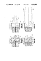
- FIG. 2 is a vertical cross-sectional view of the flame spray gun identified in the schematic view of FIG. 1.
- FIG. 3 is an exploded vertical cross-sectional view of the spray gun body member, the material spray nozzle, the flame hood assembly and the diaphragm shown in FIG. 2.
- FIG. 4 is a vertical cross-sectional view of the flame hood assembly taken along lines 4--4 of FIG. 3.
- FIG. 5 is a distal end elevation view of the diaphragm shown in FIG. 3.
- FIG. 6 is a elevation view of the distal end of the body member.
- FIG. 7 is a vertical cross-sectional view of the body member taken along lines 7--7 of FIG. 3.
- FIG. 8 is a detailed side elevation view of the hopper and eductor means shown schematically in FIG. 1.
- FIG. 9 is a horizontal cross-sectional view of the eductor means taken along lines 9--9 of FIG. 8.
- FIG. 10 is a vertical cross-sectional view of the eductor means taken along lines 10--10 of FIG. 9.
- FIG. 11 is an enlarged fragmentary view of a portion of the eductor means shown in FIG. 10.
- FIG. 12 is a partial vertical cross-sectional view of a spray gun disclosed in the prior art showing the paths of the burn air, combustible gas and particulate material as discharged into the combustion chamber.
- FIG. 13 is a partial vertical cross-sectional view of the flame "tunnel" and stream of particulate material propelled therethrough for the spray gun disclosed in FIG. 12.
- FIG. 14 is a partial vertical cross-sectional view of the spray gun disclosed herein showing the paths of the burn air, combustible gas and particulate material discharged into the combustion chamber.
- FIG. 15 is a partial vertical cross-sectional view of the flame "tunnel" and stream of particulate material propelled therethrough for the spray gun disclosed in FIG. 14.
- FIG. 16 is partial vertical cross-sectional view of a prior art spray gun showing the flame configuration emanating from the flame hood assembly.
- FIG. 17 is a partial vertical cross-sectional view of the spray gun disclosed herein showing the flame configuration emanating from the flame hood assembly.
- FIG. 1 depicts a schematic view of the flame spray gun system 20 showing the flame spray gun generally in a block diagram form at 22.
- the gun has a body 24, a flame hood assembly 26 attached thereto and a sleeve/handle 25 shown in dotted lines and that structurally surrounds the incoming burn air, particulate material and combustible gas lines as will hereinafter be shown in greater detail in FIG. 2.
- a hopper assembly 28 comprises a gravity-fed hopper 30 and a base 32 carrying an eductor mechanism.
- the hopper 30 holds a selected quantity of particulate thermoplastic material or the like and disperses the material by gravity feed in to the base 32 and the educator mechanism as will hereinafter explained in greater detail.
- a source of pressurized air 33 applies the air through a supply line 34 to a pair of conventional air pressure regulators 36 and 38.
- Regulators 36 and 38 may conveniently be mounted on the hopper assembly body 32 as shown, or may be attached to or placed on the pressurized air source, such as a steel tank or compressor. Pressurized regulated air from regulator 38 is applied directly to the gun 22 via a line or hose 54 in a manner that will be hereinafter described in greater detail.
- the pressurized regulated air from regulator 36 is applied through line 40 to a conventional pilot valve 42, which is conveniently mounted on the hopper body 32. Regulated pressurized air passes through the pilot valve 42 and through a bore disposed in the body member 32, shown generally by the line and arrow 44 therethrough, for entraining and mixing the particulate material in the pressurized air stream by eductor action from hopper 30.
- the particulate material/pressurized air mixture is applied through a line or hose 46 to a two-position three-way valve 48, and then as an output to the gun 22 via line 50 as will be hereinafter described in greater detail.
- the alternate outlet of the pilot valve 42 is connected by a line or hose 52 as another input to the valve 48 for purposes to be hereinafter further explained.
- a source of combustible gas 56 such as propane gas commonly packaged in a portable tank or canister, is applied through a conventional gas regulator 58 and a supply line or hose 60 to a conventional shut-off valve 62 and then through a line 64 to the gun 22 as will be hereinafter described in more detail.
- propane gas is supplied to the gun, and when the valve 48 is manipulated to permit the particulate thermoplastic material/pressurized air mixture from the hopper assembly 28 to be applied to the gun 22 through a supply hose 46, and burn air is supplied to the gun 22 through the supply line or hose 54, the mixture may be ignited within the flame hood assembly as will be hereinafter described in detail.
- the gun 22 basically comprises a cylindrical body member 24, a flame hood assembly 26, a material spray nozzle 80 and a flexible diaphragm 92.
- the body member 24, the material spray nozzle 80 and the flame hood assembly 26 will be described as having a "proximal" end defining the end nearest the air and gas connections, and a "distal" end defining the end most distant from the air and gas connections (see FIGS. 1, 2 and 3). Accordingly, as more clearly seen in FIG. 3, the body member 22 has a proximal end 120 and a distal end 122, while the flame hood assembly has a proximal end 128 and a distal end 129.
- the material spray nozzle has a proximal end 85 and a distal end 91.
- the body member 24 includes an elongated cylindrical section 113 integrally joined to a cylindrical section 112 of larger diameter at shoulder 110.
- the outer surface of section 112 is threaded at 109 for mating with the flame hood assembly as will be hereinafter described.
- the body member distal end 122 has a planar surface 125 transverse to the centerline of the body member, while the proximal end 120 has a planar surface 70 transverse to the body member centerline.
- a cylindrical bore 72 is disposed longitudinally through the body member 24 along its central axis and communicates with both the distal and proximal planar end faces 125 and 70, respectively.
- annular recessed ring 90 is disposed in the body member distal end surface 125 in coaxial relationship to the cylindrical bore 72 for defining a first annular chamber.
- the planar surface 125 includes an outer annular ring surface 125' and an inner annular ring surface 125" coaxially disposed with respect to bore 72 and radially separated by the coaxial first annular chamber 90.
- a first aperture or passageway 78 is disposed through the body member 24 communicating with the body member proximal end face 70 and the first annular chamber 90.
- a second aperture or passageway 76 is disposed in said body member 24 and communicates with the proximal end surface 70 and the cylindrical bore 72 intermediate its length.
- the bore 72 also has a threaded portion 86 adjacent the body member proximal end 120 for mating with the material spray nozzle 80 as will be further described below.
- the material spray nozzle comprises an elongated cylindrical member 80 having an outer diameter less than the diameter of the cylindrical bore 72 and coaxially disposed in the bore.
- the nozzle 80 has an enlarged externally threaded section 86' that removably mates with the threaded portion 86 of the bore 72 to secure the nozzle 80 therein.
- the nozzle 80 also has a second enlarged section 84 adjacent the proximal end 85 and intermediate end 85 and the enlarged externally threaded section 86'.
- the enlarged end section 84 has an annular shoulder 87 facing the threaded section 86' for engaging the proximal end face 70 of the body member when the nozzle tube 80 is threaded into the bore 72.
- a radially extending spacer 82 is mounted on the outer wall surface of the tube 80 intermediate the distal end 91 thereof and the threaded section 86'.
- the spacer 82 engages the walls of the bore 72 for maintaining the nozzle member 80 in coaxial alignment within the cylindrical bore.
- the cylindrical member 80 has a nozzle section 81 adjacent the proximal end 91 that includes an inner diameter increasing over the longitudinal length of the section towards the end 91.
- the inner surface 106 of the nozzle section 81 defines a nozzle tip having an outwardly flaring (truncated conical shape) cross-sectional configuration over the length of the nozzle section 81.
- the annular space 74 between the outer surface of the nozzle cylindrical member 80 and the coaxial bore 72 defines a third passageway disposed in the body member 24 for purposes to be hereinafter explained in greater detail.
- the flame hood assembly 26 (see FIGS. 2-7) is a generally cylindrical member having a proximal end 128 and a distal end 129.
- the flame hood assembly 26 comprises a cylindrical hood section 96 including the open end 129 and a closed end 115.
- the hood section 96 has thin cylindrical walls 97 and includes a plurality of circumferentially-spaced apertures 118 disposed radially about the circumference of the cylindrical hood section and spaced adjacent the closed end 115.
- the closed end 115 comprises a circular plate that is disposed internally of and transversely to the axis of the cylindrical hood section 96.
- the surface of the plate 115 facing the hood section open distal end 129 forms a distal planar surface 100 cooperating with the inner surfaces of the cylindrical hood walls 97 for forming a combustion chamber 99, the function of which will be hereinafter explained in greater detail.
- the other side of the plate 115 is sized to engagingly mate with the body member distal end face 122 and forms a proximal planar surface 127.
- the plate proximal planar surface 127 includes an annular recessed ring 114 disposed therein in coaxial alignment with the axis of the hood section for defining a second annular chamber. Chamber 114 is sized to register with the first annular chamber 90 disposed in the distal end face of 125 of body member 24.
- the plate 115 carries a bore 106 centrally disposed therethrough and in coaxial alignment with the axis of the flame spray hood assembly 26 and is sized to register with the cylindrical bore 72 disposed in the body member distal end 122.
- the bore 106 in plate 115 receives the projecting nozzle tip end 91 of the material spray nozzle 80, with the bore 106 increasing in diameter from the proximal planar surface side 127 to the distal planar surface side 100 to form a cross-sectional configuration of a truncated cone, the larger end of which faces toward the hood section open distal end 129.
- the plate 115 has a first circular pattern of circumferentially spaced orifices 104 disposed through the plate coaxial with the central bore 106 and communicating between the distal end face 100 of the plate and the interior of the second annular chamber 114.
- the plate 115 further has a second circular pattern of circumferentially spaced orifices 102 disposed therethrough coaxial with the central bore 106 and concentric with the first circular pattern of orifices 104.
- the second circular pattern of spaced orifices 102 are spaced radially outwardly from the first circular pattern 104, and communicate with the distal end surface 100 and with the interior of the second annular chamber 114.
- the longitudinal axes of the first and second plurality of circumferentially spaced orifices 102 and 104 define a pair of concentric annular-shaped patterns coaxially disposed with respect to the hood section axis for purposes that will be hereinafter described in greater detail.
- the proximal end 128 of the flame hood assembly 26 includes a generally cylindrical attachment section 108 that has an inner diameter coincident with the outer diameter of the body member section 112 and as disposed therein an inner threaded surface 116 for threadably mating with the body member threaded surface 109.
- the proximal end face 127 of plate 115 defines an outer annular ring surface 127' and an inner annular ring surface 127" coaxially disposed with respect to the central bore 106, and are radially separated by the coaxial second annular chamber 114.
- the diameters of the outer and inner ring surfaces 127' and 127" are identical to the diameters of the outer and inner ring surfaces 125' and 125" of the body section 24 and are sized to register therewith.
- a thin circular diaphragm 92 (see FIGS. 2, 3 and 5) is constructed of a flexible and yieldable material and is disposed between the body member distal end planar surface 125 and the hood member plate proximal planar surface 127.
- the diaphragm 92 carries a central aperture 95 therethrough, the diameter of which is identical with and registers with the diameters of the cylindrical bore 72 disposed in the body member 24, and the bore 106 opening disposed in the plate 115 proximal planar surface 127 for permitting the spray nozzle tip 91 to project therethrough as hereinabove described.
- the diaphragm also carries a plurality of circularly-spaced apertures 94 disposed therein in a pattern coaxial with the central aperture 95 and spaced radially from the aperture 95 to communicate with the body member first annular chamber 90 and the hood member plate second annular chamber 114.
- the diaphragm 92 is disposed between the body member distal end planar surface 125 and the plate proximal planar surface 127, and sealingly engages the planar surfaces 125 and 127 between the registering projecting annular planar ring surfaces 125' and 125", and 127' and 127", respectively.
- the diaphragm 92 acting as a seal between the body member 24 and the flame hood assembly 26, the first annular chamber 90 and the second annular chamber 114 are sealed together, and separated only by the flexible diaphragm 92 which has communicating apertures 94 therethrough for permitting combustible gas flow therethrough as will be hereinafter further described.
- a conventional supply line or hose connector 55 is shown attached to the proximal end 120 of the body member 24 in coaxial communication with the passageway 76 and is attached to the supply line or hose 54 for supplying pressurized burn/propelling air to the gun 22.
- a conventional line or hose connector 63 is coaxially attached to the proximal end 120 of body member 24 to communicate with the passageway 78.
- the connector 63 communicates through a rigid pipe or tubing portion 64 to a shut-off valve 62, manually operable by a projecting valve handle portion 61, and to which a flexible line or hose 60 is attached and supplies a source of regulated combustible gas (see FIG. 1).
- a conventional line or hose connector 51 is attached to the proximal end 85 of the material spray nozzle 80 for communicating with the bore 95 therethrough.
- the connector 51 has projecting coaxially therefrom a rigid tube member 50 that is connected to the two-way three-position valve 48 that was previously described with respect to FIG. 1.
- the valve 48 is manually operable by projecting handle 49, with the valve receiving the particulate material entrained in the stream of pressurized propelling air through a flexible line or hose 46.
- the valve 48 also has a second connection through a line 52 from the alternate output of the pilot valve 42 (see FIG. 1).
- a cylindrical sleeve/handle member 25 is shown surrounding the input lines 54, 46, 52 and 60 and the valves 48 and 62, with one end thereof radially mating with the smaller cylindrical portion 113 of body member 24.
- the sleeve/handle member 125 may be attached to the body member 24 by means of screws 27, or any other suitable conventional fastening mean.
- the valve operating handles 61 and 49, associated with valves 62 and 48, respectively, project through openings in the sleeve/handle member 25 for making the valve handles readily accessible for operating the valves.
- the sleeve/handle member 25 also functions to provide a grasping or handle surface for manually manipulating and handling the flame spray gun 22, as well as protecting the valves and hose connections from the various gas, air and particulate material supply lines.
- the hopper assembly includes a conically-tapering hopper 30 having a closure lid 31 vertically mounted on an eductor mechanism or means 32.
- the lower end of the hopper has a flange 130 for mating with a upper flange 138 of the eductor mechanism 32 and secured together by means of conventional fasteners, such as bolts 132.
- the eductor mechanism 32 includes a body member 136 and a vertically oriented inverted conically-shaped receiver section 134 terminating in the upwardly facing flange 138.
- the downwardly and inwardly slanting walls 134' of the conically-tapering receiver section 134 terminates in a vertically-oriented cylindrical chamber 142 within the body member 136.
- the chamber 142 has a lower closed end 145 and an upper open end 143 communicating with the receiver section 134.
- the body member 136 has disposed therethrough a horizontally-oriented cylindrical bore 44 that centrally intersects the chamber 142.
- the body member 136 are shown mounting externally thereof the pair of conventional air regulators 36 and 38 shown in FIG. 1. Pressurized air from a source 33 is applied through a fitting 34' to an internal bore (not shown for simplicity) for applying the pressurized air to the pair of regulators 36 and 38 for the purposes hereinabove discussed with respect to FIG. 1.
- a conventional pilot valve 42 is also shown externally mounted on the eductor body member 136 in communication with one end of bore 44. Regulated pressurized air from regulator 36 is applied via an internal bore or passageway (not shown) as an input to the pilot valve.
- the base of the body member 136 may have a downwardly projecting stud 140 for mounting in a matching bore of a stand or other supporting means shown generally at 141.
- the stud 140 permits the hopper assembly 28 to be attached to such a described stand or base 141 or to be removed for portable use, such as by means of straps (or a backpack unit or the like [not shown]). Connections for the supply lines or hoses 46, 52 and 54 to the flame spray gun 22 (see FIGS. 1 and 2) are shown mounted on one side of the body member 136.
- the internal horizontal bore 44 communicates between the pilot valve 42 and the connection to supply line 46.
- the portion of the horizontal bore 44 communicating between the pilot valve 42 and the chamber 142 defines a first passageway 44' in the eductor body member 136, while the portion of the bore 44 communicating between the chamber 142 and the supply line 46 defines a second passageway 44" in the body member 136.
- a nozzle having an elongated cylindrical body portion 146 and a conically-tapering nozzle tip 144 is removably insertable in the first passageway 44'.
- the outer wall surface of at least a portion of the nozzle body 146 carry threads 148 that mate with a threaded portion (not shown for simplicity) of the first passageway 44'.
- the threaded connection between the nozzle body 146 and the walls of the first bore passageway 44' permit the nozzle tip 144 to be horizontally adjustable with respect to the chamber 142 and the second passageway 44".
- the nozzle body 146 is horizontally adjusted within the bore 44' to position the conically-tapering nozzle end 144 within the chamber 142 to permit the nozzle tip 147 to project into the bore 44" but leaving sufficient annular clearance between the tapering end 144 of the nozzle and the bore 44" (as shown by the arrows) for permitting free flow of particulate thermoplastic material from the hopper 30, receiver 134 and chamber 142 into the second passageway 44".
- the pressurized air stream carried by nozzle 146 is injected into the second passageway 44' by the nozzle end 144.
- the high-velocity air stream passing into the second passageway 44" causes a lowering of the air pressure (due to venturi action) in the annular area surrounding the nozzle end 144 which is communicated to the interior of the chamber 142 and the receiver 134.
- This lowering of the air pressure in the chamber 142 causes high-velocity air flow from the chamber 142 and receiver 134 into the second passageway 44" that is shown by the arrows in FIG. 11.
- the particulate material from the chamber 142 is carried into the second passageway by eductor action and is entrained in the stream of pressurized air passing through the bore portion 44" into the gun supply hose 46.
- the adjustment of the spacing between the nozzle end 144 with relation to the junction of the chamber 142 and the bore section 44" regulates the negative pressure (developed by venturi action) in the chamber 142 and determines the flow rate of the particulate material from the hopper assembly 28 into the gun supply line 46.
- the nozzle end 144 is adjusted to obtain the highest negative pressure within the chamber 142 and thus the maximum flow rate of particulate material therefrom.
- thermoplastic particulate materials used in the flame spray process may include NUCREL, SURLYN, ELVAX products commercially available from the DuPont Corporation.
- the methods and apparatus of the present invention admit to the use of a number of feedstock materials that can be placed into the hopper assembly 28, and accordingly, the invention is not intended to be so limited to the products herein listed.
- Substantially any powderized plastic feedstock having a thermoplastic property, such as polyethylene, may be employed with good effect without departing from the spirit and scope of the invention.
- the feedstock material will preferably have a particle mesh size between 50-100 mesh.
- Some typical commercial material feedstocks will have already added thereto a number of additives which will render the feedstock more suitable to the application herein described, such as the aforementioned NUCREL and SURLYN materials.
- additives counteracting the adverse effect of light on the plastic such as a UV Stabilizer 531, or an additive such as Ergonox 1010 for improving the properties of the feedstock in the presence of heat, both such additives being commercially available from the CIBAGEIGY Company.
- talc or a like material to the feedstock material as a "slip" additive to enhance the lubricous or flowing characteristics of the particulate material or even to add some form of elastomer to improve the flexing characteristics of the spray coat applied to the article.
- Propane or another appropriate source of combustible gas will, similarly, pass through hose 60, valve 62, connector 63, first passageway 78 into the first annular chamber 90, through diaphragm apertures 94 into the second annular chamber 114, and finally through the sets of orifices 102 and 104 into chamber 99.
- the pressurized air flowing through hose 46 will be referred to as conveying air
- the pressurized air flowing through hose 54 will sometimes be referred to as propelling air.
- FIGS. 12 and 13 when viewing the hood assembly 26' from the distal end 129' along its central longitudinal axis, a circular flow of particulate material feedstock 156 has been established.
- the material entrained in conveying air is discharged out of the cylindrical nozzle bore 88'. Since the nozzle bore tip is straight, the propelling air stream 156 carrying the thermoplastic particulate material will be generally cylindrical in shape, although due to the expansion of the conveying air as it leaves the nozzle tip 88', there will be some radial expansion of the conveying air stream.
- annular propelling air flow 154 in the form of an annular ring is established as it exits the annular space between the outer surface of the nozzle tip and the bore centrally disposed thorough the plate surface 100'.
- a first annular air stream 152 is discharged through orifices 102' to form a concentric radially-spaced annular-shaped stream of air coaxially encircling the annular flow of propelling air 154 and the circular stream of particulate material and conveying air flow 156.
- An annular gas stream 150 is discharged from the orifices 104 at an oblique angle to the axis through the hood assembly 26', in a downwardly and inwardly direction as shown, to form a conically inwardly directed annular flow of gas that is coaxially and radially spaced and encircles the above described air and particulate material streams.
- the inter-section of the gas stream 150 and the air stream 152 occurs within the combustion chamber 99' intermediate the distal face 100' of the plate, and the distal end of the hood 129' and mix in a generally concentric annular stream surrounding the central annular air stream 154 and the cylindrical stream of particulate material 156.
- air from outside of the hood will be drawn into the combustion chamber 99' through the radial apertures 118' to form an annular flow of air 158 generally concentric with and surrounding the annular gas flow 150 and air flow stream 152.
- This air flow 158 also mixes with the gas and air streams 150 and 152 within the combustion chamber 99'.
- the mixing of the gas and air flows above discussed is sufficient, when ignited, to support combustion within the chamber 99', and will create a flame "tunnel" 160 (see FIG. 13).
- the flame "tunnel” 160 has a cross-sectional configuration shown diagrammatically in FIG. 13 that coaxially surrounds the stream of particulate material entrained in the mixed flows of conveying and propelling pressurized air having a cross-sectional configuration shown diagrammatically at 162 in FIG. 13.
- FIG. 16 a cross-sectional diagram of the prior art spray gun flame 165 is shown.
- the outer border of the flame envelope 165 is shown coaxially surrounding the hotter flame "tunnel" 160.
- the stream of molten particulate thermoplastic material 162 is shown propelled beyond the flame tunnel 160 within the flame boundary 165.
- the flame spray stream 162 was limited in the cross-sectional area that it could cover, as well as the cross-sectional density of the melted material within the stream. In practice, the maximum length "X" (FIG.
- FIGS. 14, 15 and 17 when viewing the hood assembly 26 from the distal end 129 along its central longitudinal axis, a circular radially expanding flow of feedstock 176 has been established.
- the material entrained in conveying air is discharged out of the cylindrical flared nozzle bore 88.
- an annular burn/propelling air flow 174 in the form of a radially expanding annular ring has been established that exits the annular space between the outer surface of the nozzle tip 91 and the surface of the bore 106 centrally disposed through plate 115 (see FIGS. 2 and 3).
- First and second annular gas streams 170 and 172 are discharged through orifices 102 and 104, respectively, to form a pair of concentric radially-spaced annular-shaped streams of gas coaxially encircling the annular flow of burn/propelling air 174 and the circular stream of conveying air and particulate material 176. Since the axis of the rings of orifices 102 and 104 are coaxial with the longitudinal axis of the gun 22 and the combustion chamber 99, the pair of concentric annular streams of gas 170 and 172 will intersect the conically-shaped expanding stream of burn/propelling air 174 that is generally concentric with the conically-shaped expending stream of conveying air and particulate material 176 expelled from the nozzle bore 88.
- annular gas streams 170 and 172 The intersection of the annular gas streams 170 and 172, the annular outwardly expanding air stream 174 and the circular outwardly expanding flow or stream of conveying air and particulate material 176 will occur in the combustion chamber 99 intermediate the plate distal surface 100 and the open distal end 129 of the hood section.
- air from outside of the hood will be drawn into the combustion chamber 99 through the radial apertures 118 to form an annular flow of air 178 generally concentric with and surrounding the pair of annular gas flows 170 and 172.
- This air flow 178 also mixes with the concentric annular streams of gas 170 and 172 within the combustion chamber 99.
- the mixing of the gas and air flows above discussed is sufficient to support combustion, when ignited, within the chamber 99, and will create a flame "tunnel" 180 having a cross-sectional configuration diagrammatically shown in FIG. 15.
- the flame "tunnel” 160 coaxially surrounds the stream 176 of particulate material entrained in a mixture of conveying and propelling air having a cross-sectional configuration diagrammatically indicated at 182 in FIG. 15.
- the streams of propelling air 174 and conveying air/particulate material 176 are radially expanding flows resulting from the flared or conically-shaped outwardly expanding shape of the plate bore 106 and the nozzle bore 88.
- This radial expansion along the longitudinal axis of the chamber 99 causes the particulate material and conveying air stream 176, and the annular propelling air stream 174 to rapidly expand outwardly at 184 (FIG. 15) to intersect and to force radially outwardly the concentric annular gas streams 172 and 170.
- This radial expansion and intersection of the air and gas streams forces the ignited flame "tunnel" outwardly to a diameter substantially coincident with the diameter of the hood walls 97.
- This action expands the cross-sectional area of the flame "tunnel” 180 on the order of 5-10 times that achieved in any prior art gun, such as that represented in FIG. 16.
- Such a magnitude of expansion of the cross-sectional area of the flame "tunnel” 180 also accommodates a greatly increased cross-sectional area of the particulate material stream 182 for greatly increasing the volume of material that can be melted and applied to the desired article surface.
- FIG. 17 a cross-sectional diagram of the improved spray gun flame is shown.
- the outer border of the flame envelope 185 is shown coaxially surrounding the hotter flame "tunnel” 180.
- the stream of molten particulate thermoplastic material 182 is shown propelled beyond the flame tunnel 180 within the flame boundaries 185.
- the transit time of the stream of particulate material 182 longitudinally through the flame "tunnel” is of critical importance to achieving proper melting of the thermoplastic material. If the transit time is too short, all of the thermoplastic material will not be properly melted and the resulting spray coated surface will be a defective combination of melted and unmelted particles.
- the transit time of the stream of particulate material 182 through the flame "tunnel" 180 may be controlled by varying the flow rate of the air propelling the particulate material into the spray gun nozzle 80 by an appropriate adjustment of the regulator 36 as will hereinafter further be described.
- the overall length "Y" of the flame 185 (see FIG. 17) is on the order of 36 inches and the diameter of the stream of particulate material shown at "B" is on the order of 3.5 to 4.5 inches, which translates to an increased cross-sectional area of 5 to 10 times the are that is capable of being achieved in the prior art gun as shown in FIG. 16.
- the longer flame length permits the spray operator to maintain a greater distance from the article surface thus reducing reflected heat and reducing operator fatigue.
- the greatly increased cross-sectional area of the particle matter stream permits more rapid coating of the article surface and reduces the number of passes necessary to coat a given square footage area. This latter reduction in time greatly increases efficiency and further reduces operator fatigue.
- settings of the regulators 36, 38 and 58 will desirably be varied in accordance with the particular coating requirements, particulate materials, and the like.
- thermoplastic materials having different properties such as melting point and the like, other settings will be necessary.
Landscapes
- Chemical & Material Sciences (AREA)
- Engineering & Computer Science (AREA)
- Combustion & Propulsion (AREA)
- Nozzles (AREA)
Abstract
Description
______________________________________ REGULATOR NUMBER FLUID TYPE PRESSURE, PSIG ______________________________________ 36Particle Conveying Air 1 38 Propelling (Flame) Air 3 58Propane 4 ______________________________________
______________________________________
REGULATOR
NUMBER    FLUID TYPE       PRESSURE, PSIG
______________________________________
36        Particle Conveying Air
                           5
38        Propelling (Flame) Air
                           8
58        Propane          10
______________________________________
Claims (23)
Priority Applications (2)
| Application Number | Priority Date | Filing Date | Title |
|---|---|---|---|
| US07/234,178 US4934595A (en) | 1988-08-19 | 1988-08-19 | Method and aparatus for spray coating |
| CA000579108A CA1295827C (en) | 1988-08-19 | 1988-10-03 | Method and apparatus for spray coating |
Applications Claiming Priority (1)
| Application Number | Priority Date | Filing Date | Title |
|---|---|---|---|
| US07/234,178 US4934595A (en) | 1988-08-19 | 1988-08-19 | Method and aparatus for spray coating |
Publications (1)
| Publication Number | Publication Date |
|---|---|
| US4934595A true US4934595A (en) | 1990-06-19 |
Family
ID=22880279
Family Applications (1)
| Application Number | Title | Priority Date | Filing Date |
|---|---|---|---|
| US07/234,178 Expired - Lifetime US4934595A (en) | 1988-08-19 | 1988-08-19 | Method and aparatus for spray coating |
Country Status (2)
| Country | Link |
|---|---|
| US (1) | US4934595A (en) |
| CA (1) | CA1295827C (en) |
Cited By (23)
| Publication number | Priority date | Publication date | Assignee | Title |
|---|---|---|---|---|
| EP0533417A1 (en) * | 1991-09-16 | 1993-03-24 | Plastic Flamecoat Systems, Inc. | Spray coating system and method |
| US5211990A (en) * | 1991-08-01 | 1993-05-18 | The Dow Chemical Company | Polyolefin flame spraying method |
| US5230470A (en) * | 1991-06-19 | 1993-07-27 | Alberta Research Council | Flame spray applicator system |
| US5269463A (en) * | 1991-09-16 | 1993-12-14 | Plastic Flamecoat Systems, Inc. | Fluidized powder feed system with pressurized hopper |
| US5297733A (en) * | 1991-09-16 | 1994-03-29 | Plastic Flamecoat Systems, Inc. | Flame spray gun |
| US5405085A (en) * | 1993-01-21 | 1995-04-11 | White; Randall R. | Tuneable high velocity thermal spray gun |
| US5445325A (en) * | 1993-01-21 | 1995-08-29 | White; Randall R. | Tuneable high velocity thermal spray gun |
| US5520334A (en) * | 1993-01-21 | 1996-05-28 | White; Randall R. | Air and fuel mixing chamber for a tuneable high velocity thermal spray gun |
| US5520736A (en) * | 1995-01-18 | 1996-05-28 | Plastic Flamecoat Systems, Inc. | Vent block for flame spray coating system |
| US5544811A (en) * | 1994-07-12 | 1996-08-13 | Acoatings, Inc. | Flame spray system and method of using the same |
| US5565241A (en) * | 1994-08-10 | 1996-10-15 | Usbi Co. | Convergent end-effector |
| US6054178A (en) * | 1995-02-21 | 2000-04-25 | Serrot International, Inc. | Fabric mesh reinforced monolithic thermoplastic membrane |
| US6311473B1 (en) * | 1999-03-25 | 2001-11-06 | Parker-Hannifin Corporation | Stable pre-mixer for lean burn composition |
| DE102004046111A1 (en) * | 2004-09-23 | 2006-04-06 | Elringklinger Ag | Process for coating flat gaskets |
| US20060086401A1 (en) * | 2004-10-25 | 2006-04-27 | Sanoh Kogyo Kabushiki Kaisha | Resin pipe |
| US20080083369A1 (en) * | 2001-09-06 | 2008-04-10 | Tatsuo Nakamura | Process and apparatus for manufacturing fiber and fiber sheet carrying solid particles and fiber and fiber sheet carrying solid particles |
| US7784306B1 (en) * | 1997-12-05 | 2010-08-31 | Innovative Materials Processing Technologies Limited | Material deposition |
| US7802376B2 (en) * | 2003-09-19 | 2010-09-28 | Huettlin Herbert | Apparatus for treating particulate material |
| ITBO20090292A1 (en) * | 2009-05-08 | 2010-11-09 | Ibix Srl | METHOD AND EQUIPMENT FOR FLAME SPRAYING OF THERMOPLASTIC POWDERS |
| US20120240852A1 (en) * | 2011-03-23 | 2012-09-27 | Kevin Wayne Ewers | System for spraying metal particulate |
| US20150182989A1 (en) * | 2009-01-14 | 2015-07-02 | Resodyn Corporation | Flameless thermal spray system using flame heat source |
| KR20170000925A (en) | 2015-06-25 | 2017-01-04 | 주식회사 코코솔 | Plastic powder thermal spray coating equipment and thereof plastic powder thermal spray coating gun |
| US10328398B2 (en) | 2001-01-12 | 2019-06-25 | Diversey, Inc. | Multiple function dispenser |
Citations (9)
| Publication number | Priority date | Publication date | Assignee | Title |
|---|---|---|---|---|
| US2544259A (en) * | 1944-11-25 | 1951-03-06 | Duccini Gaetano | Metallizing spray gun |
| US2594222A (en) * | 1948-09-27 | 1952-04-22 | C E Freeman Co Inc | Manifold for molten material spray guns |
| US2643955A (en) * | 1950-08-26 | 1953-06-30 | Union Carbide & Carbon Corp | Method of and apparatus for flame spraying polyethylene and other plastics |
| US3073528A (en) * | 1958-03-28 | 1963-01-15 | Metco Inc | Control valving system for flame spraying apparatus |
| US3415450A (en) * | 1966-05-24 | 1968-12-10 | Coast Metals Inc | Powder supply construction for spray torch |
| US3441215A (en) * | 1967-03-03 | 1969-04-29 | Coast Metals Inc | Powder spray torch |
| US3442454A (en) * | 1965-04-17 | 1969-05-06 | Siemens Ag | Power suction device |
| SU197708A1 (en) * | 1966-03-23 | 1973-01-08 | ALL-UNION ISH.-uul - • 'YUK''YY <(.?> &'? 3! THihl ^ it-Abfr: '.- EUi.'tiB ^' - | €: LIO ^ TKA (TERL10 | |
| US4632309A (en) * | 1984-09-11 | 1986-12-30 | Plastic Flamecoat Systems, Inc. | Method and apparatus for spray coating |
-
1988
- 1988-08-19 US US07/234,178 patent/US4934595A/en not_active Expired - Lifetime
- 1988-10-03 CA CA000579108A patent/CA1295827C/en not_active Expired - Lifetime
Patent Citations (9)
| Publication number | Priority date | Publication date | Assignee | Title |
|---|---|---|---|---|
| US2544259A (en) * | 1944-11-25 | 1951-03-06 | Duccini Gaetano | Metallizing spray gun |
| US2594222A (en) * | 1948-09-27 | 1952-04-22 | C E Freeman Co Inc | Manifold for molten material spray guns |
| US2643955A (en) * | 1950-08-26 | 1953-06-30 | Union Carbide & Carbon Corp | Method of and apparatus for flame spraying polyethylene and other plastics |
| US3073528A (en) * | 1958-03-28 | 1963-01-15 | Metco Inc | Control valving system for flame spraying apparatus |
| US3442454A (en) * | 1965-04-17 | 1969-05-06 | Siemens Ag | Power suction device |
| SU197708A1 (en) * | 1966-03-23 | 1973-01-08 | ALL-UNION ISH.-uul - • 'YUK''YY <(.?> &'? 3! THihl ^ it-Abfr: '.- EUi.'tiB ^' - | €: LIO ^ TKA (TERL10 | |
| US3415450A (en) * | 1966-05-24 | 1968-12-10 | Coast Metals Inc | Powder supply construction for spray torch |
| US3441215A (en) * | 1967-03-03 | 1969-04-29 | Coast Metals Inc | Powder spray torch |
| US4632309A (en) * | 1984-09-11 | 1986-12-30 | Plastic Flamecoat Systems, Inc. | Method and apparatus for spray coating |
Cited By (26)
| Publication number | Priority date | Publication date | Assignee | Title |
|---|---|---|---|---|
| US5230470A (en) * | 1991-06-19 | 1993-07-27 | Alberta Research Council | Flame spray applicator system |
| US5211990A (en) * | 1991-08-01 | 1993-05-18 | The Dow Chemical Company | Polyolefin flame spraying method |
| EP0533417A1 (en) * | 1991-09-16 | 1993-03-24 | Plastic Flamecoat Systems, Inc. | Spray coating system and method |
| US5269463A (en) * | 1991-09-16 | 1993-12-14 | Plastic Flamecoat Systems, Inc. | Fluidized powder feed system with pressurized hopper |
| US5282573A (en) * | 1991-09-16 | 1994-02-01 | Plastic Flamecoat Systems, Inc. | Spray coating system and method |
| US5297733A (en) * | 1991-09-16 | 1994-03-29 | Plastic Flamecoat Systems, Inc. | Flame spray gun |
| US5405085A (en) * | 1993-01-21 | 1995-04-11 | White; Randall R. | Tuneable high velocity thermal spray gun |
| US5445325A (en) * | 1993-01-21 | 1995-08-29 | White; Randall R. | Tuneable high velocity thermal spray gun |
| US5520334A (en) * | 1993-01-21 | 1996-05-28 | White; Randall R. | Air and fuel mixing chamber for a tuneable high velocity thermal spray gun |
| US5544811A (en) * | 1994-07-12 | 1996-08-13 | Acoatings, Inc. | Flame spray system and method of using the same |
| US5565241A (en) * | 1994-08-10 | 1996-10-15 | Usbi Co. | Convergent end-effector |
| US5520736A (en) * | 1995-01-18 | 1996-05-28 | Plastic Flamecoat Systems, Inc. | Vent block for flame spray coating system |
| US6054178A (en) * | 1995-02-21 | 2000-04-25 | Serrot International, Inc. | Fabric mesh reinforced monolithic thermoplastic membrane |
| US7784306B1 (en) * | 1997-12-05 | 2010-08-31 | Innovative Materials Processing Technologies Limited | Material deposition |
| US6311473B1 (en) * | 1999-03-25 | 2001-11-06 | Parker-Hannifin Corporation | Stable pre-mixer for lean burn composition |
| US10850241B2 (en) | 2001-01-12 | 2020-12-01 | Diversey, Inc. | Multiple function dispenser |
| US10328398B2 (en) | 2001-01-12 | 2019-06-25 | Diversey, Inc. | Multiple function dispenser |
| US20080083369A1 (en) * | 2001-09-06 | 2008-04-10 | Tatsuo Nakamura | Process and apparatus for manufacturing fiber and fiber sheet carrying solid particles and fiber and fiber sheet carrying solid particles |
| US7802376B2 (en) * | 2003-09-19 | 2010-09-28 | Huettlin Herbert | Apparatus for treating particulate material |
| DE102004046111A1 (en) * | 2004-09-23 | 2006-04-06 | Elringklinger Ag | Process for coating flat gaskets |
| US20060086401A1 (en) * | 2004-10-25 | 2006-04-27 | Sanoh Kogyo Kabushiki Kaisha | Resin pipe |
| US20150182989A1 (en) * | 2009-01-14 | 2015-07-02 | Resodyn Corporation | Flameless thermal spray system using flame heat source |
| ITBO20090292A1 (en) * | 2009-05-08 | 2010-11-09 | Ibix Srl | METHOD AND EQUIPMENT FOR FLAME SPRAYING OF THERMOPLASTIC POWDERS |
| US8544408B2 (en) * | 2011-03-23 | 2013-10-01 | Kevin Wayne Ewers | System for applying metal particulate with hot pressurized air using a venturi chamber and a helical channel |
| US20120240852A1 (en) * | 2011-03-23 | 2012-09-27 | Kevin Wayne Ewers | System for spraying metal particulate |
| KR20170000925A (en) | 2015-06-25 | 2017-01-04 | 주식회사 코코솔 | Plastic powder thermal spray coating equipment and thereof plastic powder thermal spray coating gun |
Also Published As
| Publication number | Publication date |
|---|---|
| CA1295827C (en) | 1992-02-18 |
Similar Documents
| Publication | Publication Date | Title |
|---|---|---|
| US4934595A (en) | Method and aparatus for spray coating | |
| US5732885A (en) | Internal mix air atomizing spray nozzle | |
| RU2645562C2 (en) | Method and apparatus for flame spraying thermoplastic powders | |
| US2544259A (en) | Metallizing spray gun | |
| US2513081A (en) | Multichromatic spraying apparatus | |
| US4993642A (en) | Paint spray gun | |
| US5285967A (en) | High velocity thermal spray gun for spraying plastic coatings | |
| US2786779A (en) | Method and apparatus for powdered metal deposition by oxy-fuel gas flame | |
| US5209405A (en) | Baffle for hvlp paint spray gun | |
| US4632309A (en) | Method and apparatus for spray coating | |
| US5297733A (en) | Flame spray gun | |
| US5148986A (en) | High pressure thermal spray gun | |
| US3415450A (en) | Powder supply construction for spray torch | |
| US3027096A (en) | Methods and apparatus for producing multi-component surface coatings | |
| US4561808A (en) | Powder feed pickup device for thermal spray guns | |
| US3111267A (en) | Apparatus for applying heat-fusible coatings on solid objects | |
| CA2054528C (en) | Spray coating system and method | |
| US2436335A (en) | Spray device for projecting molten particles | |
| US3709434A (en) | Process and apparatus for coating objects with powdery substances | |
| US5230470A (en) | Flame spray applicator system | |
| NZ204545A (en) | Oxy-acetylene cutting torch:converging nozzle | |
| US2427448A (en) | Apparatus for producing vitreous or metallic surfaces | |
| US2726118A (en) | Apparatus for the spraying of pulverulent materials | |
| US3438579A (en) | Apparatus for flame spraying powdered materials | |
| KR101723487B1 (en) | Plastic powder thermal spray coating equipment and thereof plastic powder thermal spray coating gun |
Legal Events
| Date | Code | Title | Description |
|---|---|---|---|
| AS | Assignment |
Owner name: PLASTIC FLAMECOAT SYSTEMS, INC., A CORP. OF TEXAS Free format text: ASSIGNMENT OF ASSIGNORS INTEREST.;ASSIGNOR:REIMER, JAMES H.;REEL/FRAME:004952/0939 Effective date: 19880818 |
|
| STCF | Information on status: patent grant |
Free format text: PATENTED CASE |
|
| AS | Assignment |
Owner name: PFS ACQUISITION, INC. A CORP. OF TEXAS Free format text: ASSIGNMENT OF ASSIGNORS INTEREST.;ASSIGNORS:REIMER, JAMES H.;JENNINGS, GEORGE E.;REEL/FRAME:005877/0993 Effective date: 19910620 Owner name: PLASTIC FLAMECOAT SYSTEMS, INC. Free format text: ASSIGNMENT OF ASSIGNORS INTEREST.;ASSIGNOR:PFS ACQUISITION, INC.;REEL/FRAME:005877/0997 Effective date: 19910620 Owner name: JENNINGS, GEORGE E. Free format text: ASSIGNMENT OF ASSIGNORS INTEREST.;ASSIGNOR:PLASTIC FLAMECOAT SYSTEMS, INC. A CORP. OF TEXAS;REEL/FRAME:005877/0989 Effective date: 19910620 Owner name: REIMER, JAMES H. Free format text: ASSIGNMENT OF ASSIGNORS INTEREST.;ASSIGNOR:PLASTIC FLAMECOAT SYSTEMS, INC. A CORP. OF TEXAS;REEL/FRAME:005877/0989 Effective date: 19910620 |
|
| FPAY | Fee payment |
Year of fee payment: 4 |
|
| AS | Assignment |
Owner name: PFS THERMOPLASTIC POWDER COATINGS, INC., TEXAS Free format text: CHANGE OF NAME;ASSIGNOR:PLASTIC FLAMECOAT SYSTEMS, INC.;REEL/FRAME:008366/0632 Effective date: 19960216 |
|
| FPAY | Fee payment |
Year of fee payment: 8 |
|
| AS | Assignment |
Owner name: WB POWDER COATINGS, LLC, TEXAS Free format text: MERGER;ASSIGNOR:PFS THERMOPLASTIC POWDER COATINGS, INC.;REEL/FRAME:010892/0701 Effective date: 20000427 |
|
| AS | Assignment |
Owner name: INNOTEK WORLD RESINS, LLC, TEXAS Free format text: CHANGE OF NAME;ASSIGNOR:WB POWDER COATINGS, LLC;REEL/FRAME:010892/0754 Effective date: 20000512 |
|
| FPAY | Fee payment |
Year of fee payment: 12 |