US4934406A - Throttling valve - Google Patents
Throttling valve Download PDFInfo
- Publication number
- US4934406A US4934406A US06/926,320 US92632086A US4934406A US 4934406 A US4934406 A US 4934406A US 92632086 A US92632086 A US 92632086A US 4934406 A US4934406 A US 4934406A
- Authority
- US
- United States
- Prior art keywords
- armature
- valve
- flexure element
- coil
- permanent magnet
- Prior art date
- Legal status (The legal status is an assumption and is not a legal conclusion. Google has not performed a legal analysis and makes no representation as to the accuracy of the status listed.)
- Expired - Fee Related
Links
- 239000012530 fluid Substances 0.000 claims description 4
- 238000004804 winding Methods 0.000 claims description 4
- 238000004891 communication Methods 0.000 claims description 3
- 239000003380 propellant Substances 0.000 description 10
- 239000007800 oxidant agent Substances 0.000 description 5
- 239000000446 fuel Substances 0.000 description 4
- 239000007788 liquid Substances 0.000 description 4
- 229920001971 elastomer Polymers 0.000 description 3
- 239000000806 elastomer Substances 0.000 description 3
- 238000004519 manufacturing process Methods 0.000 description 3
- 238000006073 displacement reaction Methods 0.000 description 2
- 238000003754 machining Methods 0.000 description 2
- 239000000203 mixture Substances 0.000 description 2
- 238000007789 sealing Methods 0.000 description 2
- 125000006850 spacer group Chemical group 0.000 description 2
- 230000003068 static effect Effects 0.000 description 2
- 238000002485 combustion reaction Methods 0.000 description 1
- 230000009977 dual effect Effects 0.000 description 1
- 230000004907 flux Effects 0.000 description 1
- 238000000034 method Methods 0.000 description 1
Images

Classifications
-
- F—MECHANICAL ENGINEERING; LIGHTING; HEATING; WEAPONS; BLASTING
- F16—ENGINEERING ELEMENTS AND UNITS; GENERAL MEASURES FOR PRODUCING AND MAINTAINING EFFECTIVE FUNCTIONING OF MACHINES OR INSTALLATIONS; THERMAL INSULATION IN GENERAL
- F16K—VALVES; TAPS; COCKS; ACTUATING-FLOATS; DEVICES FOR VENTING OR AERATING
- F16K31/00—Actuating devices; Operating means; Releasing devices
- F16K31/02—Actuating devices; Operating means; Releasing devices electric; magnetic
- F16K31/06—Actuating devices; Operating means; Releasing devices electric; magnetic using a magnet, e.g. diaphragm valves, cutting off by means of a liquid
- F16K31/10—Actuating devices; Operating means; Releasing devices electric; magnetic using a magnet, e.g. diaphragm valves, cutting off by means of a liquid with additional mechanism between armature and closure member
-
- Y—GENERAL TAGGING OF NEW TECHNOLOGICAL DEVELOPMENTS; GENERAL TAGGING OF CROSS-SECTIONAL TECHNOLOGIES SPANNING OVER SEVERAL SECTIONS OF THE IPC; TECHNICAL SUBJECTS COVERED BY FORMER USPC CROSS-REFERENCE ART COLLECTIONS [XRACs] AND DIGESTS
- Y10—TECHNICAL SUBJECTS COVERED BY FORMER USPC
- Y10T—TECHNICAL SUBJECTS COVERED BY FORMER US CLASSIFICATION
- Y10T137/00—Fluid handling
- Y10T137/8593—Systems
- Y10T137/87153—Plural noncommunicating flow paths
- Y10T137/87161—With common valve operator
Definitions
- the present invention is generally directed to flow control valves and, more particularly, bi-propellant valves that control separate flows in substantially constant proportion over a range of flow rates.
- the servo valve determines the sizes of the orifice in the venturi throat and, thus, the flow rate.
- the venturi throats are designed such that critical flow is maintained over a range of flow rates.
- the venturi ports continuously provide throttled liquids over the range of flow rates.
- the servo valve is powered by internal line pressure from liquid fuel on-board the rocket. This avoids the need for hydraulics or large on-board power supply systems.
- this system also has several disadvantages. It is inefficient in that fuel that is vented to adjust the position of the valve, together with quiescent leakage of the servo valve, is merely dumped overboard. Also, manufacture of the pintles required high precision machining and matching as well as high surface finishes. The necessary contours, surface areas and finishes of the pintles are difficult to attain and to reliably reproduce.
- a mechanically balanced dual valve is actuated by a torque motor having an electromagnetic stator and an armature that pivots in response to energization of the stator.
- the assembly further includes a valve body that has first and second internal seats that respectively communicate with first and second inlet ports and first and second outlet ports.
- First and second valve members that extend inside the valve body are connected to the armature of the torque motor such that they move in an opposite sense in response to the pivotal movement of the armature.
- the valve members cooperate with the respective valve seats to control fluid flow between the inlets and outlets of the valve body.
- a flexure element provides cantilevered support for the armature and the valve members are connected to opposite ends of the armature.
- the valve members are provided with a molded elastomer to form a seal between the valve members and their respective valve seats.
- the stator includes a permanent magnet that produces a torque on the armature, but the flexure element has a spring rate such that it produces a higher torque on the armature.
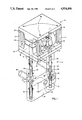
- FIG. 1 is an exploded orthographic view of a bi-propellant valve in accordance with the subject invention.
- FIG. 2 is an elevation view of the bi-propellant valve of FIG. 1 with portions thereof broken away to better disclose the internal structure of the valve.
- the bi-propellant valve disclosed herein includes an actuator 10 and a valve 12.
- Actuator 10 is a torque motor that includes first and second pole pieces 14 and 16 that are fastened together by screws 18.
- Four permanent magnets 20 with respective spacers 22 are arranged end-to-end and secured between respective corners of pole pieces 14 and 16 by screws 18.
- Pole piece 16 is secured to a manifold 24.
- An armature 26 is located between pole pieces 14 and 16 as well as between oppositely disposed and permanent magnets 20. Armature 26 is supported in cantilevered fashion by a flexure element 28 and spacer 30 which are secured to pole piece 16. Under static conditions, the spring rate of flexure element 28 is sufficient to maintain armature 26 in a substantially central position at times when the torque motor is not electrically energized. Two electrical coils 32 and 34 are maintained between pole pieces 14 and 16 such that armature 26 extends through the central hole of both coils. Coils 32 and 34 are wound in the same direction and electrically connected in series.
- Valve 12 includes a valve body 36 that is secured to manifold 24 by cap screws 38.
- Valve body 36 includes valve cavities 40 and 42 having internal seats 44 and 46 respectively.
- Valve cavity 40 is in communication with inlet 48 and outlet 50.
- Valve cavity 42 is in communication with inlet 52 and outlet 54.
- Valve members 56 and 58 extend into valve cavities 40 and 42 respectively.
- Valve member 56 includes poppet 60, valve stem 62 and extension 64.
- valve member 58 includes poppet 66, valve stem 68 and extension 70.
- Valve stems 62 and 68 are threadingly connected to opposite ends of armature 26 by threaded rods 72 and 74.
- a seal 76 is provided around valve stem 62 and a seal 78 is provided around extension 64 to prevent fluid leakage between body 36 and valve member 56. Seal 76 is maintained in valve body 36 by manifold 24 and seal 78 is maintained by a cover 80 secured by cap screws 82. Similarly, with valve member 58, a seal 84 is provided around valve stem 68 and a seal 86 is provided around extension 70 to prevent leakage of fluid between valve member 58 and body 36. Seal 84 is maintained in valve body 36 by manifold 24 and seal 86 is maintained by cover 88 secured by cap screws 90.
- permanent magnets 20 and flexure element 28 maintain armature 26 in equilibrium position. In equilibrium position the ends of armature 26 are balanced substantially midway between pole pieces 14 and 16. The air gap between armature 26 and pole piece 14 is substantially equal to the air gap between armature 26 and pole piece 16. Permanent magnets 20 are included between pole pieces 14 and 16 of the actuator to better linearize the armature response to current in coils 32 and 34; to limit power requirements for the actuator; and to lower the response time for the actuator by increasing baseline magnetic flux density. The torque in armature 26 developed by permanent magnets 20 alone is insufficient to overcome the counter-torque provided by flexure element 28. Thus, armature 26 remains in its equilibrium position as long as coils 32 and 34 are de-energized.
- armature 26 The ends of armature 26 are connected to valve members 56 and 58 by adjustment threads such that, when armature 26 is in the equilibrium position, poppet 60 is lightly biased against internal seat 44 to form a seal between inlet 48 and outlet 50 and poppet 66 is lightly biased against internal seat 46 to form a seal between inlet 52 and outlet 54.
- poppet 60 is lightly biased against internal seat 44 to form a seal between inlet 48 and outlet 50
- poppet 66 is lightly biased against internal seat 46 to form a seal between inlet 52 and outlet 54.
- the degree of displacement of armature 26 between the open and closed positions determines the size of the valve orifice between internal seats 44 and 46 and poppets 60 and 66 respectively.
- the degree of displacement of armature 26 is substantially directly proportional to the current in coils 32 and 34. In this manner, the flow of oxidizer and propellant through the valve is substantially proportional to the current applied to coils 32 and 34.
- the flow rates of liquids through the valve are controlled without high-precision machining by controlling the current to coils 32 and 34.
- the poppet valves are oriented in opposite sense to make them compatible with the fundamental operation of the torque motor.
- the fuel and oxidizer poppets are contoured to maintain a constant mixture ratio throughout the throttling range.
- the mixture ratio is determined by the relative porting of valve cavities 40 and 42 in the valve body. This is accomplished with well-known manufacturing processes that are less expensive and have a higher degree of repeatability than the processes required by prior art devices.
- the sealing surfaces 92 and 94 of poppets 60 and 66 are coated with a molded elastomer 96 and 98 to provide better shutoff and sealing conditions. The compressibility of the elastomer permits both poppets to shut off substantially simultaneously.
Landscapes
- Engineering & Computer Science (AREA)
- General Engineering & Computer Science (AREA)
- Mechanical Engineering (AREA)
- Magnetically Actuated Valves (AREA)
Abstract
Description
Claims (2)
Priority Applications (1)
| Application Number | Priority Date | Filing Date | Title |
|---|---|---|---|
| US06/926,320 US4934406A (en) | 1986-11-03 | 1986-11-03 | Throttling valve |
Applications Claiming Priority (1)
| Application Number | Priority Date | Filing Date | Title |
|---|---|---|---|
| US06/926,320 US4934406A (en) | 1986-11-03 | 1986-11-03 | Throttling valve |
Publications (1)
| Publication Number | Publication Date |
|---|---|
| US4934406A true US4934406A (en) | 1990-06-19 |
Family
ID=25453052
Family Applications (1)
| Application Number | Title | Priority Date | Filing Date |
|---|---|---|---|
| US06/926,320 Expired - Fee Related US4934406A (en) | 1986-11-03 | 1986-11-03 | Throttling valve |
Country Status (1)
| Country | Link |
|---|---|
| US (1) | US4934406A (en) |
Cited By (2)
| Publication number | Priority date | Publication date | Assignee | Title |
|---|---|---|---|---|
| WO1994013984A1 (en) * | 1992-12-07 | 1994-06-23 | George S. Cole & Associates, Incorporated | Pinch valve |
| US20110198528A1 (en) * | 2008-08-13 | 2011-08-18 | Rolf Prettl | Directional control fluid valve |
Citations (9)
| Publication number | Priority date | Publication date | Assignee | Title |
|---|---|---|---|---|
| DE801872C (en) * | 1949-09-28 | 1951-01-25 | Maschf Augsburg Nuernberg Ag | Relieved poppet valve |
| US3289687A (en) * | 1964-02-13 | 1966-12-06 | J C Dunaway | Actuator for pure fluid amplifier |
| US3414012A (en) * | 1967-06-28 | 1968-12-03 | William C Mcnutt | Dual latching solenoid valve |
| US3499463A (en) * | 1967-11-20 | 1970-03-10 | Sperry Rand Ltd | Electrohydraulic servo valve |
| US3510100A (en) * | 1966-07-22 | 1970-05-05 | Bell Aerospace Corp | Zero leakage poppet valve |
| US3589677A (en) * | 1966-12-12 | 1971-06-29 | Henri Segers | Piston valve |
| US3945607A (en) * | 1974-11-08 | 1976-03-23 | Consolidated Brass Company | Pressure safety valve |
| US4428188A (en) * | 1978-12-06 | 1984-01-31 | Textron Inc. | Bistable fuel valve |
| US4561632A (en) * | 1983-09-21 | 1985-12-31 | J. Lorch Gesellschaft & Co. Kg | Solenoid valve |
-
1986
- 1986-11-03 US US06/926,320 patent/US4934406A/en not_active Expired - Fee Related
Patent Citations (9)
| Publication number | Priority date | Publication date | Assignee | Title |
|---|---|---|---|---|
| DE801872C (en) * | 1949-09-28 | 1951-01-25 | Maschf Augsburg Nuernberg Ag | Relieved poppet valve |
| US3289687A (en) * | 1964-02-13 | 1966-12-06 | J C Dunaway | Actuator for pure fluid amplifier |
| US3510100A (en) * | 1966-07-22 | 1970-05-05 | Bell Aerospace Corp | Zero leakage poppet valve |
| US3589677A (en) * | 1966-12-12 | 1971-06-29 | Henri Segers | Piston valve |
| US3414012A (en) * | 1967-06-28 | 1968-12-03 | William C Mcnutt | Dual latching solenoid valve |
| US3499463A (en) * | 1967-11-20 | 1970-03-10 | Sperry Rand Ltd | Electrohydraulic servo valve |
| US3945607A (en) * | 1974-11-08 | 1976-03-23 | Consolidated Brass Company | Pressure safety valve |
| US4428188A (en) * | 1978-12-06 | 1984-01-31 | Textron Inc. | Bistable fuel valve |
| US4561632A (en) * | 1983-09-21 | 1985-12-31 | J. Lorch Gesellschaft & Co. Kg | Solenoid valve |
Cited By (4)
| Publication number | Priority date | Publication date | Assignee | Title |
|---|---|---|---|---|
| WO1994013984A1 (en) * | 1992-12-07 | 1994-06-23 | George S. Cole & Associates, Incorporated | Pinch valve |
| US5402823A (en) * | 1992-12-07 | 1995-04-04 | George S. Cole & Associates, Incorporated | Pinch valve |
| US20110198528A1 (en) * | 2008-08-13 | 2011-08-18 | Rolf Prettl | Directional control fluid valve |
| US8403002B2 (en) * | 2008-08-13 | 2013-03-26 | Rolf Prettl | Directional control fluid valve |
Similar Documents
| Publication | Publication Date | Title |
|---|---|---|
| US3961644A (en) | Flat seat valve, in particular, for the control of fuel metering devices | |
| US3570806A (en) | Balanced electromechanical control valve | |
| US4442998A (en) | Electromagnetic valve unit | |
| US5301921A (en) | Proportional electropneumatic solenoid-controlled valve | |
| US4131130A (en) | Pneumatic pressure control valve | |
| US5407174A (en) | Proportional electropneumatic solenoid-controlled valve | |
| US4574841A (en) | Rocker lever solenoid valve | |
| US4513780A (en) | Solenoid valve | |
| US3209782A (en) | Flapper valves | |
| US11214375B2 (en) | Spring sealed pneumatic servo valve | |
| US3373769A (en) | Valve for controlling simultaneously the flow of two separate fluids | |
| US3926405A (en) | Solenoid operated proportional valve | |
| US6390129B2 (en) | Proportional solenoid-operated fluid metering device | |
| US6290203B1 (en) | Pilot operated valve assembly | |
| US5064166A (en) | Solenoid valve with high flow capacity and low energy consumption | |
| US6786236B2 (en) | Electrohydraulic servo valve | |
| US3401711A (en) | Single receiver port jet displacement servovalve | |
| US20020000255A1 (en) | Balanced fluid control valve | |
| US4773445A (en) | Solenoid valve | |
| US4561629A (en) | Solenoid valve | |
| US4832313A (en) | Solenoid valve | |
| US4934406A (en) | Throttling valve | |
| US3218022A (en) | Adjustable solenoid operated valve | |
| US10822094B2 (en) | Pneumatic servo valve with adjustable metering members | |
| US11566722B2 (en) | Servo valve |
Legal Events
| Date | Code | Title | Description |
|---|---|---|---|
| AS | Assignment |
Owner name: PARKER-HANNIFIN CORPORATION, 17325 EUCLID AVENUE, Free format text: ASSIGNMENT OF ASSIGNORS INTEREST.;ASSIGNOR:MAYFIELD, WILLIAM B.;REEL/FRAME:004638/0581 Effective date: 19861027 Owner name: PARKER-HANNIFIN CORPORATION, A CORP OF OH,OHIO Free format text: ASSIGNMENT OF ASSIGNORS INTEREST;ASSIGNOR:MAYFIELD, WILLIAM B.;REEL/FRAME:004638/0581 Effective date: 19861027 |
|
| FEPP | Fee payment procedure |
Free format text: PAYOR NUMBER ASSIGNED (ORIGINAL EVENT CODE: ASPN); ENTITY STATUS OF PATENT OWNER: LARGE ENTITY |
|
| FPAY | Fee payment |
Year of fee payment: 4 |
|
| FPAY | Fee payment |
Year of fee payment: 8 |
|
| REMI | Maintenance fee reminder mailed | ||
| LAPS | Lapse for failure to pay maintenance fees | ||
| STCH | Information on status: patent discontinuation |
Free format text: PATENT EXPIRED DUE TO NONPAYMENT OF MAINTENANCE FEES UNDER 37 CFR 1.362 |
|
| FP | Lapsed due to failure to pay maintenance fee |
Effective date: 20020619 |