US4930739A - Cabinet drawer guide attachment and adjustment assembly - Google Patents
Cabinet drawer guide attachment and adjustment assembly Download PDFInfo
- Publication number
- US4930739A US4930739A US07/222,508 US22250888A US4930739A US 4930739 A US4930739 A US 4930739A US 22250888 A US22250888 A US 22250888A US 4930739 A US4930739 A US 4930739A
- Authority
- US
- United States
- Prior art keywords
- bracket
- mounting
- slide
- drawer
- mounting bracket
- Prior art date
- Legal status (The legal status is an assumption and is not a legal conclusion. Google has not performed a legal analysis and makes no representation as to the accuracy of the status listed.)
- Expired - Fee Related
Links
- 230000037431 insertion Effects 0.000 claims 1
- 238000003780 insertion Methods 0.000 claims 1
- 230000000717 retained effect Effects 0.000 abstract description 3
- 230000009471 action Effects 0.000 abstract description 2
- 238000009434 installation Methods 0.000 description 11
- 230000000712 assembly Effects 0.000 description 3
- 238000000429 assembly Methods 0.000 description 3
- 239000002184 metal Substances 0.000 description 3
- 238000004519 manufacturing process Methods 0.000 description 2
- 239000000463 material Substances 0.000 description 2
- 238000000034 method Methods 0.000 description 2
- 238000012986 modification Methods 0.000 description 2
- 230000004048 modification Effects 0.000 description 2
- 239000004033 plastic Substances 0.000 description 2
- 229920003023 plastic Polymers 0.000 description 2
- 239000004677 Nylon Substances 0.000 description 1
- 239000004698 Polyethylene Substances 0.000 description 1
- 229910000639 Spring steel Inorganic materials 0.000 description 1
- 230000004075 alteration Effects 0.000 description 1
- 230000003466 anti-cipated effect Effects 0.000 description 1
- 230000013011 mating Effects 0.000 description 1
- 229920001778 nylon Polymers 0.000 description 1
- -1 polyethylene Polymers 0.000 description 1
- 229920000573 polyethylene Polymers 0.000 description 1
- 230000001737 promoting effect Effects 0.000 description 1
- 239000002023 wood Substances 0.000 description 1
Images


Classifications
-
- A—HUMAN NECESSITIES
- A47—FURNITURE; DOMESTIC ARTICLES OR APPLIANCES; COFFEE MILLS; SPICE MILLS; SUCTION CLEANERS IN GENERAL
- A47B—TABLES; DESKS; OFFICE FURNITURE; CABINETS; DRAWERS; GENERAL DETAILS OF FURNITURE
- A47B88/00—Drawers for tables, cabinets or like furniture; Guides for drawers
- A47B88/40—Sliding drawers; Slides or guides therefor
- A47B88/473—Braking devices, e.g. linear or rotational dampers or friction brakes; Buffers; End stops
- A47B88/477—Buffers; End stops
-
- A—HUMAN NECESSITIES
- A47—FURNITURE; DOMESTIC ARTICLES OR APPLIANCES; COFFEE MILLS; SPICE MILLS; SUCTION CLEANERS IN GENERAL
- A47B—TABLES; DESKS; OFFICE FURNITURE; CABINETS; DRAWERS; GENERAL DETAILS OF FURNITURE
- A47B2210/00—General construction of drawers, guides and guide devices
- A47B2210/0002—Guide construction for drawers
- A47B2210/0051—Guide position
- A47B2210/0054—Adjustment of position of slides
-
- A—HUMAN NECESSITIES
- A47—FURNITURE; DOMESTIC ARTICLES OR APPLIANCES; COFFEE MILLS; SPICE MILLS; SUCTION CLEANERS IN GENERAL
- A47B—TABLES; DESKS; OFFICE FURNITURE; CABINETS; DRAWERS; GENERAL DETAILS OF FURNITURE
- A47B2210/00—General construction of drawers, guides and guide devices
- A47B2210/0002—Guide construction for drawers
- A47B2210/0051—Guide position
- A47B2210/0059—Guide located at the side of the drawer
Definitions
- Drawer guides are used in the cabinetry industry to allow sliding movement of drawers in and out of a cabinet.
- the drawer guides can be mounted over, under, or on the side of the drawer box.
- the drawer guides can be made of various materials, i.e. metal, wood or plastic.
- Drawer guides or slides can allow for partial or full extension of the drawer box from within the cabinet.
- a drawer slide typicallY consists of a guiding channel within which rollers mounted on the side of the drawer box are laterally retained, yet the rollers move freely along the channel. The rollers are attached to the case or drawer box using nails, screws or other attachment techniques.
- the drawer slide In cabinetry wherein the side, front frame and rear walls are all interconnected forming a box or case, the drawer slide is normally attached to the front and the rear or back of the cabinet.
- the typical slide mounting procedure is to insert the drawer slide into a mating plastic or metal receptacle, and then attach the receptacle in some manner to the back of the cabinet. If the rear of the drawer slide has been attached to the cabinet back at the factory, a problem can arise thereafter during the installation of the cabinet if uneven or unsguare walls of the installation site pull the cabinet out of square. If the back or rear end of the drawer slide has no lateral movement or adjustment capability, then the drawer front will not properly fit flush against the front of the cabinet when the drawer is moved into the non-square cabinet along the drawer slides.
- a drawer slide rear bracket which consists of two parts, a rear bracket and a slide end bracket installable separately and then matably connected without tools, would simplify installation and improve manufacturing processes by reducing labor costs in the cabinetry industry.
- the other piece is fastened to the inside of the cabinet back.
- the first piece is pushed into the second piece and retained by spring-clip detent action. Horizontal sliding movement of the clipped portion of the second piece in the first piece is possible when needed for adjustment of the slides to establish parallelism of the drawer front with the cabinet front, without adjustment of the piece fastened to the cabinet back.
- the first piece may be a spring metal mounting bracket which has a rear surface adapted for mounting to the inside back wall of the cabinet, and an upper surface and a lower surface projecting from the rear surface toward the front of the cabinet. The upper and lower surfaces are vertically spaced a distance less than the diameter of a cylindrical plug portion of the second piece so the second piece is resiliently gripped tiqhtly in the first, but can be horizontally displaced to the extent needed for the adjustment desired.
- a general object of the invention is to provide an improved bracket assembly for use in cabinetry as a drawer slide rear mounting bracket.
- Another object is to provide a bracket assembly which allows for lateral adjustment of the drawer slides after installation of the slides and the bracket.
- Another object of the invention is to provide for more economical installation of the bracket assembly during the manufacture of cabinetry.
- a further object of the invention is to provide a simplified means for realignment of drawer boxes to cabinetry fronts once a cabinet assembly is installed in a room or building having unsquare mounting surfaces.
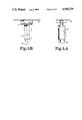
- FIG. 1A is a side view of the drawer slide end bracket according to a typical embodiment of this invention.
- FIG. 1B is a bottom plan view of the drawer slide end bracket shown in FIG. 1A.
- FIG. 1C is a front end view of the drawer, slide end bracket shown in FIG. 1A.
- FIG. 2A is a front view of the rear mounting bracket of the typical embodiment of this present invention.
- FIG. 2B is a bottom plan view of the mounting bracket shown in FIG. 2A.
- FIG. 2C is a cross sectional view looking in the direction of the arrows 2C--2C in FIG. 2B.
- FIG. 2D is a cross sectional view looking in the direction of the arrows 2D--2D in FIG. 2B.
- FIG. 3A is a top view of a cabinet frame assembly showing a drawer box mounted to drawer slides and the cabinetry having a non-square installation site with the drawer slides unadjusted.
- FIG. 3B is a top view of a cabinetry assembly in an unsquare installation site and showing a drawer box, a front and rear wall, and the present invention connected to the drawer slides facilitating the proper alignment of the drawer box.
- FIG. 4A is side view of the slide bracket assembly according to one embodiment of the present invention.
- FIG. 4B is a top view of the bracket assembly shown in FIG. 4A illustrating one possible adjustment of the bracket to counteract an unsquare mounting.
- FIG. 1A A side view of drawer slide end bracket 12 according to a typical embodiment of this invention is shown in FIG. 1A.
- the bracket 12 consists of a cylindrical portion 14, a slide end receiving portion 16, and a central portion joining the cylindrical portion and the slide end receiving portion, the central portion being the interconnecting portion 18.
- the profile height of the interconnecting portion 18, shown in FIG. 1A, is less than the diameter of the cylindrical portion 14.
- the slide end receiving portion 16 is shown in one form designed to receive a particular style and design of drawer slide. It should be noted, however, that the slide end receiving portion 16 can be configured to receive a variety of commercially available drawer slides.
- cylindrical portion 14 is shown attached along its entire length to the interconnecting portion 18. This provides for a maximum amount of support and structural strength between cylindrical portion 14 and drawer receiving portion 16.
- the channel 17 is sized and shaped to snugly fit a drawer slide as the slide is inserted into the slide end bracket.
- the slide end bracket is made from nylon, polyethylene, or other similar moldable, lightweight, strong materials.
- Bracket 19 would normally be made of spring steel of a thickness sufficient enough to support the anticipated weight of the drawer mounted to the drawer slide.
- the mounting bracket 19 is secured to a rear wall of the cabinetry by inserting tab 20 into a locating hole in the cabinet back and screwing a screw into hole 22 from the inside area of the cabinet or by installing a pop rivet drawn back through the front side of hole 22 and secured from the rear side of the cabinet, at the factory,
- the cylindrical portion 14 of the slide end bracket 12 is inserted between the detented portions 24 of the mounting bracket.
- the retaining portions 26 act to retain the cylindrical portion 14 of slide end bracket 12 in FIG. 1A from escaping the channel defined by the upper and lower retaining portions 26. End stops 28 prevent the cylindrical portion 14 of end bracket 12 of FIG. 1A from escaping the lateral ends of the mounting bracket during the adjustment of slide end bracket 12 of FIG. 1A between the end stops of the mounting bracket 19.
- FIG. 2B shows a bottom view of mounting bracket 19. End stops 28 are once again visible, and their central location along the edge of the surface 30 further reveals their functionality in retaining the cylindrical portion 14 of slide end bracket 12 once portion 14 is inserted between the surfaces 30 of mounting bracket 19 in FIG. 2A.
- FIG. 2C is a sectional view looking in the direction of the arrows 2C--2C in FIG. 2B.
- the distance between clamping surfaces 32 is dimensionally sized to be slightly smaller than the diameter of the cylindrical portion 14 of slide end bracket 12 in FIG. IA.
- the retaining portions 26 are also shown in FIG. 2C.
- FIG. 2D is a sectional view looking in the direction of the arrows 2D--2D in FIG. 2B.
- the detented portions 24 taper out for receiving the cylindrical portion 14 of slide end bracket 12 in FIG. 1A. It should also be noted that the detented portions extend along the length of mounting bracket 19 in FIG. 2A for a distance slightly greater than the horizontal width of cylindrical portion 14 of end bracket 12 shown in FIG. 1B.
- a typical installation procedure would include inserting the slide end receiving portion 16 of the slide end bracket 12 in FIG. 1A onto a drawer slide.
- Tab 20 of the mounting bracket 19 would be located in a hole in the rear wall 44 of the cabinet shown in FIG. 3A.
- Bracket 19 of FIG. 2A would be attached to the rear wall by a screw or pop-rivet inserted into hole 22 of FIG. 2A placed adjacent to the locating tab to assure horizontal mounting of the bracket.
- FIG. 3A depicts the top view of a cabinetry frame installed in an out-of-square building corner 45, for example.
- the condition is shown exaggerated for ease of illustration.
- a gap 40 is produced between the cabinet front and the drawer front 48 due to the unsquare relation of the cabinet back 44 with the cabinet front wall 42, resulting from the constraints of the installation site.
- Adjusting the bracket assemblies 46, by sliding the cylindrical portions 14 to the right in the spring clip brackets 19, will cause the gap 40 to be eliminated by establishing parallelism of the drawer front flange 48 and the cabinet front wall 42.
- FIG. 3B shows the results of the adjustment of bracket assemblies 46 wherein the drawer front flange 48 and the cabinet front wall 42 are perfectly aligned and no gap exists along the drawer front flange 48 and the cabinetry front wall 42.
- Drawer slides 50 are moved either individually, or together with the drawer front flange 48 positioned between the slides to move the slides simultaneously to perfect an alignment suitable to overcome the non-squareness of the cabinet frame due to the installation site.
- FIG. 4A depicting the bracket assembly rotated 90 degrees from a normal viewing angle for engineering drawing relationship with FIG. 4B.
- the slide 50 is shown inserted into the slide end bracket 12, and the end bracket cylindrical portion 14 is shown inserted into the mounting bracket 19.
- the mounting bracket 19 is shown mounted to cabinet back 44.
- FIG. 4B illustrates in the dashed lines, a lateral adjustment of the end bracket 12 within the mounting bracket 19 as in FIG. 3B, accomplished without the aid of special tools or requiring removal of the bracket assembly and remounting.
Landscapes
- Drawers Of Furniture (AREA)
Abstract
Description
Claims (6)
Priority Applications (2)
| Application Number | Priority Date | Filing Date | Title |
|---|---|---|---|
| US07/222,508 US4930739A (en) | 1988-07-21 | 1988-07-21 | Cabinet drawer guide attachment and adjustment assembly |
| US07/569,771 US5025545A (en) | 1988-07-21 | 1990-08-21 | Method of attaching and adjusting a cabinet drawer guide assembly |
Applications Claiming Priority (1)
| Application Number | Priority Date | Filing Date | Title |
|---|---|---|---|
| US07/222,508 US4930739A (en) | 1988-07-21 | 1988-07-21 | Cabinet drawer guide attachment and adjustment assembly |
Related Child Applications (1)
| Application Number | Title | Priority Date | Filing Date |
|---|---|---|---|
| US34170090A Division | 1988-07-21 | 1990-04-17 |
Publications (1)
| Publication Number | Publication Date |
|---|---|
| US4930739A true US4930739A (en) | 1990-06-05 |
Family
ID=22832512
Family Applications (1)
| Application Number | Title | Priority Date | Filing Date |
|---|---|---|---|
| US07/222,508 Expired - Fee Related US4930739A (en) | 1988-07-21 | 1988-07-21 | Cabinet drawer guide attachment and adjustment assembly |
Country Status (1)
| Country | Link |
|---|---|
| US (1) | US4930739A (en) |
Citations (3)
| Publication number | Priority date | Publication date | Assignee | Title |
|---|---|---|---|---|
| US3149811A (en) * | 1962-09-17 | 1964-09-22 | Ajax Hardware Mfg Corp | Mounting bracket for elongated track |
| US3675883A (en) * | 1970-09-17 | 1972-07-11 | Ajax Hardware Mfg Corp | Adjustable bracket assembly for use as a rear drawer slide bracket and the like |
| US4176890A (en) * | 1978-04-05 | 1979-12-04 | Ajax Hardware Corporation | Drawer and support system |
-
1988
- 1988-07-21 US US07/222,508 patent/US4930739A/en not_active Expired - Fee Related
Patent Citations (3)
| Publication number | Priority date | Publication date | Assignee | Title |
|---|---|---|---|---|
| US3149811A (en) * | 1962-09-17 | 1964-09-22 | Ajax Hardware Mfg Corp | Mounting bracket for elongated track |
| US3675883A (en) * | 1970-09-17 | 1972-07-11 | Ajax Hardware Mfg Corp | Adjustable bracket assembly for use as a rear drawer slide bracket and the like |
| US4176890A (en) * | 1978-04-05 | 1979-12-04 | Ajax Hardware Corporation | Drawer and support system |
Similar Documents
| Publication | Publication Date | Title |
|---|---|---|
| US7014282B2 (en) | Pull-out guide for drawers | |
| AT398512B (en) | FITTING FOR THE ADJUSTABLE BRACKET OF A DRAWER EXTENSION GUIDE | |
| AU2007293953B2 (en) | Drawer | |
| CA1303115C (en) | Device for fastening a front plate to metal drawer side walls | |
| US4441773A (en) | Bottom mounted drawer slide assembly | |
| US5002346A (en) | Means for positioning the false front of drawers | |
| US5025545A (en) | Method of attaching and adjusting a cabinet drawer guide assembly | |
| US5224322A (en) | Wall construction, with wall components fixed by means of blind couplings to framework components | |
| US5295327A (en) | Sheet metal door frame and a method for installing the same in a doorway | |
| EP0017399B1 (en) | A window lining arrangement, particularly for inclined windows | |
| US4930739A (en) | Cabinet drawer guide attachment and adjustment assembly | |
| US7331644B2 (en) | Stay-closed drawer slide with socket | |
| GB2101653A (en) | Means for interconnecting panels | |
| US4840512A (en) | Fitting for fastening the rail member of a drawer | |
| US4741583A (en) | Fastening device for adjustable front plates | |
| US4556205A (en) | Gauging tool | |
| US4552415A (en) | Adjustable drawer mounting assembly | |
| US4741628A (en) | Cabinet and drawer guide assembly | |
| US4650263A (en) | Structural support and thin panel assembly | |
| CN110829310A (en) | Partition wall adjustable bottom box structure and mounting method | |
| EP0649617A1 (en) | Fastening device especially for cupboard-bases plinths | |
| EP3401479A1 (en) | Device for moving a furniture part which is held on a furniture body of a piece of furniture | |
| EP0984126B1 (en) | Guiding device for a sliding door | |
| DE8707366U1 (en) | Office desk | |
| GB2078099A (en) | Improvements in shelf assemblies |
Legal Events
| Date | Code | Title | Description |
|---|---|---|---|
| AS | Assignment |
Owner name: HAAS CABINET CO., INC., 625 WEST UTICA ST. SELLERS Free format text: ASSIGNMENT OF ASSIGNORS INTEREST.;ASSIGNOR:BROWN, JAMES L.;REEL/FRAME:004951/0863 Effective date: 19880713 Owner name: HAAS CABINET CO., INC., 625 WEST UTICA ST. SELLERS Free format text: ASSIGNMENT OF ASSIGNORS INTEREST;ASSIGNOR:BROWN, JAMES L.;REEL/FRAME:004951/0863 Effective date: 19880713 |
|
| FEPP | Fee payment procedure |
Free format text: PAYOR NUMBER ASSIGNED (ORIGINAL EVENT CODE: ASPN); ENTITY STATUS OF PATENT OWNER: SMALL ENTITY |
|
| FPAY | Fee payment |
Year of fee payment: 4 |
|
| REMI | Maintenance fee reminder mailed | ||
| LAPS | Lapse for failure to pay maintenance fees | ||
| FP | Lapsed due to failure to pay maintenance fee |
Effective date: 19980610 |
|
| STCH | Information on status: patent discontinuation |
Free format text: PATENT EXPIRED DUE TO NONPAYMENT OF MAINTENANCE FEES UNDER 37 CFR 1.362 |