US4930338A - Pipe expanding mandrel - Google Patents
Pipe expanding mandrel Download PDFInfo
- Publication number
- US4930338A US4930338A US07/309,871 US30987189A US4930338A US 4930338 A US4930338 A US 4930338A US 30987189 A US30987189 A US 30987189A US 4930338 A US4930338 A US 4930338A
- Authority
- US
- United States
- Prior art keywords
- engagement
- set pin
- mandrel
- sleeve
- pipe expanding
- Prior art date
- Legal status (The legal status is an assumption and is not a legal conclusion. Google has not performed a legal analysis and makes no representation as to the accuracy of the status listed.)
- Expired - Lifetime
Links
- 230000008878 coupling Effects 0.000 claims abstract description 12
- 238000010168 coupling process Methods 0.000 claims abstract description 12
- 238000005859 coupling reaction Methods 0.000 claims abstract description 12
- 238000000034 method Methods 0.000 description 4
- 238000010276 construction Methods 0.000 description 2
- 238000006073 displacement reaction Methods 0.000 description 1
- 238000003780 insertion Methods 0.000 description 1
- 230000037431 insertion Effects 0.000 description 1
- 230000013011 mating Effects 0.000 description 1
- 238000000926 separation method Methods 0.000 description 1
Images


Classifications
-
- B—PERFORMING OPERATIONS; TRANSPORTING
- B21—MECHANICAL METAL-WORKING WITHOUT ESSENTIALLY REMOVING MATERIAL; PUNCHING METAL
- B21D—WORKING OR PROCESSING OF SHEET METAL OR METAL TUBES, RODS OR PROFILES WITHOUT ESSENTIALLY REMOVING MATERIAL; PUNCHING METAL
- B21D39/00—Application of procedures in order to connect objects or parts, e.g. coating with sheet metal otherwise than by plating; Tube expanders
- B21D39/08—Tube expanders
- B21D39/20—Tube expanders with mandrels, e.g. expandable
-
- Y—GENERAL TAGGING OF NEW TECHNOLOGICAL DEVELOPMENTS; GENERAL TAGGING OF CROSS-SECTIONAL TECHNOLOGIES SPANNING OVER SEVERAL SECTIONS OF THE IPC; TECHNICAL SUBJECTS COVERED BY FORMER USPC CROSS-REFERENCE ART COLLECTIONS [XRACs] AND DIGESTS
- Y10—TECHNICAL SUBJECTS COVERED BY FORMER USPC
- Y10T—TECHNICAL SUBJECTS COVERED BY FORMER US CLASSIFICATION
- Y10T29/00—Metal working
- Y10T29/53—Means to assemble or disassemble
- Y10T29/53113—Heat exchanger
- Y10T29/53122—Heat exchanger including deforming means
Definitions
- This invention relates to improvements in pipe expanding mandrels for use in pipe expanding operations in which the mandrel is used by being inserted under pressure into the pipe to be expanded.
- a pipe expanding mandrel of this type requires change in the size of the pipe expanding billet at the front end of the mandrel according to a desired change in the diameter of the pipe to be expanded.
- replacing the entire mandrel each time when there is a change in desired pipe diameter involves removal of the mandrel from and mounting another mandrel to the pipe expanding apparatus. Such mounting and removing operations are very troublesome and time-consuming.
- This invention is directed to overcoming the aforesaid difficulty with the prior art, and therefore it is a primary object of the invention to provide a pipe expanding mandrel which requires no troublesome operation including pin removal and insertion as has hitherto been involved in connection with each replacement of a pipe expanding billet.
- the present invention enables the replacement of the pipe expanding billet by a far more easy and simple way of operation.
- the invention is intended to solve the problem with the prior art by providing a member readily engageable with and disengageable from a mandrel shaft and having a pipe expanding billet fixed to the member, instead of mounting the billet directly to the mandrel shaft as is usual with the prior art.
- the pipe expanding mandrel in accordance with the invention comprises a set pin having a pipe expanding billet in a front end portion thereof and having a reduced stepped portion formed behind the billet; a sleeve fitted on the set pin at a position behind the stepped portion and having axially oriented elongate slots formed therein, the elongate slots being engaged by a turn stopper pin extending transversely through the set pin; a spring interposed between the stepped portion of the set pin and the front end of the sleeve and which urges the stepped portion and the front end of the sleeve away from each other; an engagement protuberance formed in a rear end portion of the set pin and an engagement hole bored in a front end portion of a mandrel shaft, said engagement protuberance and engagement hole constituting means for coupling the set pin and the mandrel shaft together, free from the possibility of their becoming disengaged from each other, when the engagement protuberance is brought in engagement with the engagement hole and turned a predetermined degree
- the operation of coupling the set pin having the pipe expanding billet to the mandrel shaft can be performed by bringing the engagement protuberance provided in the rear end portion of the set pin into engagement with the engagement hole provided in the front end portion of the mandrel shaft and thereafter turning them relative to each other.
- the sleeve is moved toward the rear end of the spring, that is, toward the front end of the mandrel shaft, to bring the engagement lugs into firm engagement with the engagement groove in the rear end portion of the sleeve, whereby any accidental turning and displacement of the sleeve can be positively prevented, which ensures accurate engagement of the engagement protuberance with the engagement hole for coupling of the set pin with the mandrel shaft.
- the shaft portion extending from the rear end of the engagement protuberance of the set pin is fitted in the hole located at the back of the engagement hole of the mandrel shaft, whereby possible jolting of the set pin can be prevented.
- the set pin can be coupled to the mandrel shaft, free from the possibility of their becoming disengaged from each other, by turning the set pin relative to the mandrel shaft, and the sleeve is fitted on the set pin so that the mandrel shaft is prevented from turning.
- the set pin when the set pin is coupled with the mandrel shaft, the set pin is positively prevented from being inadvertently turned relative to the mandrel shaft to cause their disengagement from each other.
- the invention is advantageous in that the required operation can be performed easily and quickly, with a great improvement being thus assured in operating efficiency.
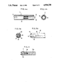
- FIG. 1 is a half-cut sectional view in front elevation showing one form of mandrel embodying the invention
- FIG. 2 is a sectional view showing a pipe expanding billet as it appears in the process of mounting and removing operation
- FIGS. 3 to 5 are views showing components, of which FIG. 3(a) is a schematic view showing the configuration of a rear end portion of a set pin; FIG. 3(b) is a schematic plan view thereof; FIG. 4(a) is a sectional view of a sleeve; FIG. 4(b) is a right side view thereof; FIG. 5(b) is a schematic front view showing a front end portion of a mandrel shaft; and FIG. 5(a) is a left side view thereof;
- FIG. 6 is a sectional view showing principal portions of a conventional arrangement.
- numeral 1 generally designates a set pin having a hollow pipe-expanding billet 3 threadedly fixed to its front end portion through the intermediary of a threaded shaft 2, a reduced stepped portion 4 formed behind the billet 3, and a male threaded portion 5 formed behind the stepped portion 4.
- a flat engagement protuberance 6 having a flat circular shape extends from a rear end portion of the set pin 1, and an extension shaft portion 31 extends from the rear end of the engagement protuberance 6.
- Numeral 7 designates a generally cylindrical sleeve which, as FIG. 4a shows, has an internally threaded portion 8 formed on the inner periphery thereof, two axially oriented elongate slots 9, 9. and tongue-like engagement lugs 10, 10 formed at the rear end.
- the externally threaded portion 5 of the set pin 1 threadedly extends through the internally threaded portion 8 formed on the inner periphery of the sleeve 7 so that the sleeve 7 is slidably fitted on a shaft portion behind the stepped portion of the set pin 1.
- a turn stopper pin 11 is disposed at a predetermined position between the stepped portion 4 and the externally threaded portion 5 of the set pin 1 and extends transversely through the set pin 1, the turn stopper pin 11 being in engagement at both ends thereof with the elongate slots 9, 9 of the sleeve 7 so as to prevent rotation between the set pin 1 and the sleeve 7.
- a spring 12 which acts to resiliently widen the space between the two portions by urging the sleeve 7 backward, that is, in the direction of the arrow a.
- Numeral 13 designates an elongate column-shaped mandrel shaft having a small-diameter stepped portion 14 at the front end thereof, an engagement groove 15 of a predetermined width at the front end thereof, an engagement hole 16 formed behind the engagement groove 15 in continuation therefrom, the engagement hole 16 being dimensionally larger than the width of the engagement groove 15 and being spherically shaped or circular shaped as viewed in side elevation, and a hole portion 32 extending rearward from the engagement hole 16.
- Numeral 17 designates a hole bored in the front end portion of the mandrel shaft 13 in superposed relation with the engagement groove 15, the hole 17 being deep enough to reach the engagement hole 16.
- the sleeve 7 is fitted on the set pin 1. With the mandrel positioned as shown, the sleeve 7 is drawn in the direction of the arrow b against the biasing force of the spring 12 to allow the rear end of the set pin 1 to project from the sleeve 7, as FIG. 2 shows, so that the engagement protuberance 6 at the rear end of the set pin 1 is inserted into the engagement hole 16 of the mandrel shaft 13 through the engagement groove 15 and hole 17. Simultaneously, the shaft portion 31 extending from the rear end of the engagement protuberance 6 is fitted into the hole portion 32 behind the engagement hole 16 of the mandrel shaft 13.
- the sleeve 7 and the set pin 1 are turned 90 degrees so that the engagement protuberance 6 is turned while in agreement with the configuration of the engagement hole 16. Therefore, through the engagement of the engagement protuberance 6 of the set pin 1 with the engagement hole 16, the set pin 1 is coupled to the mandrel shaft 13, free from slip-off possibility. Since the shaft portion 31 is fitted into the hole portion 32, the set pin 1 is prevented from any separation by jolting.
- the sleeve 7 is moved in the direction of the arrow a under the biasing force of the spring 12 until it is fitted on the small-diameter stepped portion 14. In that position, as FIG. 1 shows, the engagement lugs 10, 10 at the rear end of the sleeve 7 is fitted into the engagement groove 15 of the mandrel shaft 13.
- the engagement groove 15 and the engagement lugs 10, 10 are positively prevented from rotating relative to the mandrel 13.
- the fitting of the sleeve 7 over the small-diameter stepped portion 14 of the mandrel shaft 13 provides satisfactory axial alignment of the sleeve 7 and the mandrel shaft 13.
- the sleeve 7 is first advanced in the direction of the arrow b to release the engagement between the engagement lugs 10, 10 of the sleeve 7 and the engagement groove 15 of the mandrel shaft 13. Then, the sleeve 7 and the set pin 1 are turned 90 degrees to release the engagement between the engagement protuberance 6 of the set pin 1 and the engagement hole 16 of the mandrel shaft 13, as well as the engagement between the shaft portion 31 and the hole portion 32.
- This operation is very simple and can be performed easily and quickly without the use of any tool.
- the internal thread portion 8 and external thread portion 5 formed respectively on the sleeve 7 and on the set pin 1 prevent the slipping off of the sleeve 7 from the rear side of the set pin 1 which would otherwise occur under the biasing force of the spring 12, because the thread portions 8, 5 abut against each other to lock the one to the other.
- Such non-disengageability provides ease of handling with respect to components.
- the pipe expanding billet 3 is constructed separately from the set pin 1. It is to be understood, however, that in the invention the mounting construction of the pipe expanding billet 3 relative to the set pin 1 is not limited.
- the pipe expanding billet 3 and the set pin 1 may be integrally constructed to form onesingle unit.
- the engement protuberance 6 at the rear end of the set pin 1 is of a flat circular shape and the engagement hole 16 of the mandrel shaft 13 is so configured as to match the shape of the engagement protuberance 6.
- the configurations of the engagement protuberance 6 and engagement hole 16 are not limited to those shown.
- an engagement protuberance 6 is provided in a front end portion of the mandrel shaft 13 while an engagement hole 16 is provided in a rear end portion of the set pin 1.
- set pin 1 and the mandrel shaft 13 be individually provided in their respective rear end and front end portions with one or the other of such engagement protuberance 6 and engagement hole 16 as are engageable with each other to permit them to be non-disengageably coupled together through their turning a predetermined angle.
- the tongue-like lugs 10, 10 provided at the rear end of the sleeve 7 are engageable with the engagement groove 15 provided in continuation to the engagement hole 16 of the mandrel shaft 13. It is understood, however, that in the invention the construction of the engagement lugs 10, 10 and engagement groove 15 are not limited to that shown. It is possible that separately from the engagement hole 16, an engagement groove 15 may be provided in a front end portion of the mandrel shaft 13. Of course, it is also possible that engagement lugs 10 may be provided in the mandrel shaft 13 on one hand, while on the other hand an engagement groove 15 may be provided on the sleeve side.
- engagement lugs 10 and an engagement groove 15 which are engageable together to permit the sleeve 7 and the mandrel shift 13 to be coupled to each other so as to prevent them from turning.
- the number of engagement lugs, etc. is not particularly limited.
- the arrangement of the set pin 1, sleeve 7, and other components is not limited to that shown in the foregoing embodiment.
- the provision of the external and internal thread portions 5, 8 as anti-slip off means is not an essential requirement.
Landscapes
- Engineering & Computer Science (AREA)
- Mechanical Engineering (AREA)
- Extrusion Of Metal (AREA)
Abstract
Description
Claims (8)
Priority Applications (1)
| Application Number | Priority Date | Filing Date | Title |
|---|---|---|---|
| US07/309,871 US4930338A (en) | 1989-02-14 | 1989-02-14 | Pipe expanding mandrel |
Applications Claiming Priority (1)
| Application Number | Priority Date | Filing Date | Title |
|---|---|---|---|
| US07/309,871 US4930338A (en) | 1989-02-14 | 1989-02-14 | Pipe expanding mandrel |
Publications (1)
| Publication Number | Publication Date |
|---|---|
| US4930338A true US4930338A (en) | 1990-06-05 |
Family
ID=23200040
Family Applications (1)
| Application Number | Title | Priority Date | Filing Date |
|---|---|---|---|
| US07/309,871 Expired - Lifetime US4930338A (en) | 1989-02-14 | 1989-02-14 | Pipe expanding mandrel |
Country Status (1)
| Country | Link |
|---|---|
| US (1) | US4930338A (en) |
Cited By (10)
| Publication number | Priority date | Publication date | Assignee | Title |
|---|---|---|---|---|
| US4980966A (en) * | 1990-04-27 | 1991-01-01 | Burr Oak Tool & Gauge Company | Rod holder for the assembly of heat exchangers |
| US5097590A (en) * | 1990-11-21 | 1992-03-24 | Kyoshi Kogyo Kabushiki Kaisha | Mandrel for vertical-type pipe expanding apparatus |
| AT396208B (en) * | 1991-06-14 | 1993-07-26 | Vaillant Gmbh | TUBE EXPANDING TOOL |
| US5407494A (en) * | 1993-12-21 | 1995-04-18 | Crs Holdings, Inc. | Method of fabricating a welded metallic duct assembly |
| US5640879A (en) * | 1993-09-25 | 1997-06-24 | Behr Gmbh & Co. | Method and device for expanding metal tubes |
| US5826457A (en) * | 1997-07-11 | 1998-10-27 | Eagles; Allen S. | Wheel for mandrel of pipe straightening presses |
| US5983698A (en) * | 1998-02-18 | 1999-11-16 | Tseng; Shao-Chien | Easy removed die core device used for cold swaging |
| US20130269408A1 (en) * | 2010-12-20 | 2013-10-17 | Hirotec Corporation | Metal pipe, and method and device for processing the same |
| CN103418700A (en) * | 2013-09-04 | 2013-12-04 | 中山市奥美森工业有限公司 | Expansion head assembly |
| CN110479884A (en) * | 2019-08-14 | 2019-11-22 | 苏州瑞美科材料科技有限公司 | A kind of position switching mechanism |
Citations (6)
| Publication number | Priority date | Publication date | Assignee | Title |
|---|---|---|---|---|
| US1235835A (en) * | 1916-03-06 | 1917-08-07 | Nilson Bros | Flue-expander. |
| US3568303A (en) * | 1967-05-02 | 1971-03-09 | Akio Ito | Method for working a yoke of a smallsized electric machine |
| US4263713A (en) * | 1978-10-16 | 1981-04-28 | Westinghouse Electric Corp. | Apparatus for actuating and extracting a tube guide-expander |
| US4573340A (en) * | 1983-02-28 | 1986-03-04 | K-Line Industries, Inc. | Valve guide liner broaching tool |
| US4644775A (en) * | 1985-06-14 | 1987-02-24 | Fuchs Jr Francis J | Shell forming apparatus and process |
| US4779445A (en) * | 1987-09-24 | 1988-10-25 | Foster Wheeler Energy Corporation | Sleeve to tube expander device |
-
1989
- 1989-02-14 US US07/309,871 patent/US4930338A/en not_active Expired - Lifetime
Patent Citations (6)
| Publication number | Priority date | Publication date | Assignee | Title |
|---|---|---|---|---|
| US1235835A (en) * | 1916-03-06 | 1917-08-07 | Nilson Bros | Flue-expander. |
| US3568303A (en) * | 1967-05-02 | 1971-03-09 | Akio Ito | Method for working a yoke of a smallsized electric machine |
| US4263713A (en) * | 1978-10-16 | 1981-04-28 | Westinghouse Electric Corp. | Apparatus for actuating and extracting a tube guide-expander |
| US4573340A (en) * | 1983-02-28 | 1986-03-04 | K-Line Industries, Inc. | Valve guide liner broaching tool |
| US4644775A (en) * | 1985-06-14 | 1987-02-24 | Fuchs Jr Francis J | Shell forming apparatus and process |
| US4779445A (en) * | 1987-09-24 | 1988-10-25 | Foster Wheeler Energy Corporation | Sleeve to tube expander device |
Cited By (12)
| Publication number | Priority date | Publication date | Assignee | Title |
|---|---|---|---|---|
| US4980966A (en) * | 1990-04-27 | 1991-01-01 | Burr Oak Tool & Gauge Company | Rod holder for the assembly of heat exchangers |
| US5097590A (en) * | 1990-11-21 | 1992-03-24 | Kyoshi Kogyo Kabushiki Kaisha | Mandrel for vertical-type pipe expanding apparatus |
| AT396208B (en) * | 1991-06-14 | 1993-07-26 | Vaillant Gmbh | TUBE EXPANDING TOOL |
| US5640879A (en) * | 1993-09-25 | 1997-06-24 | Behr Gmbh & Co. | Method and device for expanding metal tubes |
| US5887476A (en) * | 1993-09-25 | 1999-03-30 | Behr Gmbh & Co. | Method and device for expanding metal tubes |
| US5407494A (en) * | 1993-12-21 | 1995-04-18 | Crs Holdings, Inc. | Method of fabricating a welded metallic duct assembly |
| US5826457A (en) * | 1997-07-11 | 1998-10-27 | Eagles; Allen S. | Wheel for mandrel of pipe straightening presses |
| US5983698A (en) * | 1998-02-18 | 1999-11-16 | Tseng; Shao-Chien | Easy removed die core device used for cold swaging |
| US20130269408A1 (en) * | 2010-12-20 | 2013-10-17 | Hirotec Corporation | Metal pipe, and method and device for processing the same |
| CN103418700A (en) * | 2013-09-04 | 2013-12-04 | 中山市奥美森工业有限公司 | Expansion head assembly |
| CN103418700B (en) * | 2013-09-04 | 2015-12-16 | 奥美森智能装备股份有限公司 | Swollen head group part |
| CN110479884A (en) * | 2019-08-14 | 2019-11-22 | 苏州瑞美科材料科技有限公司 | A kind of position switching mechanism |
Similar Documents
| Publication | Publication Date | Title |
|---|---|---|
| US2987334A (en) | Tool holders | |
| US5855377A (en) | Dead length collect chuck assembly | |
| AU681222B2 (en) | System for coupling machine tools | |
| US4834597A (en) | Tool assembly, tool components and method of assemblying said components | |
| EP0382723B1 (en) | Pressure-tight plug coupling | |
| US4872710A (en) | Releasable quick connect fitting | |
| AU765865B2 (en) | Toolholder assembly | |
| JP2657425B2 (en) | Apparatus for adapting a tool holder to be attached to a base member | |
| US4684284A (en) | Anti-rotation lock assembly | |
| US6929266B2 (en) | Bit holder | |
| US6386789B1 (en) | Quick release ball type locking pin and production tool | |
| US4930338A (en) | Pipe expanding mandrel | |
| US4913607A (en) | Tool coupling | |
| EP0640894A1 (en) | Connection of a band to a watch case | |
| KR102284552B1 (en) | A clamping device | |
| US6503027B2 (en) | Cutting tool assembly | |
| US7380836B2 (en) | Connection device for fluid lines | |
| JP2002137111A (en) | Speedily exchangeable mandrel assembly for use together with hole saw and pilot drill bit | |
| US4905964A (en) | Swivelable connector for tubular conduits | |
| US2832254A (en) | Nut and expanding sleeve retainer therefor | |
| US4088008A (en) | Quick release adapter and tool combination | |
| US3633931A (en) | Quick-change chucks | |
| US2719722A (en) | Quick change tool holder | |
| US4978262A (en) | Tool coupling between a toolholder and a machine spindle | |
| US7118089B2 (en) | Fluid coupler |
Legal Events
| Date | Code | Title | Description |
|---|---|---|---|
| AS | Assignment |
Owner name: KYOSHIN KOGYO KABUSHIKI KAISHA, JAPAN Free format text: ASSIGNMENT OF ASSIGNORS INTEREST.;ASSIGNOR:TOKURA, KENGI;REEL/FRAME:005042/0645 Effective date: 19890110 |
|
| STCF | Information on status: patent grant |
Free format text: PATENTED CASE |
|
| FEPP | Fee payment procedure |
Free format text: PAYOR NUMBER ASSIGNED (ORIGINAL EVENT CODE: ASPN); ENTITY STATUS OF PATENT OWNER: SMALL ENTITY Free format text: PAYER NUMBER DE-ASSIGNED (ORIGINAL EVENT CODE: RMPN); ENTITY STATUS OF PATENT OWNER: SMALL ENTITY |
|
| FEPP | Fee payment procedure |
Free format text: PAYOR NUMBER ASSIGNED (ORIGINAL EVENT CODE: ASPN); ENTITY STATUS OF PATENT OWNER: SMALL ENTITY |
|
| FPAY | Fee payment |
Year of fee payment: 4 |
|
| FPAY | Fee payment |
Year of fee payment: 8 |
|
| FEPP | Fee payment procedure |
Free format text: PAYER NUMBER DE-ASSIGNED (ORIGINAL EVENT CODE: RMPN); ENTITY STATUS OF PATENT OWNER: SMALL ENTITY Free format text: PAYOR NUMBER ASSIGNED (ORIGINAL EVENT CODE: ASPN); ENTITY STATUS OF PATENT OWNER: SMALL ENTITY |
|
| FPAY | Fee payment |
Year of fee payment: 12 |