US4929957A - Method and apparatus for detecting receiver compression in multiple lobe guidance systems - Google Patents
Method and apparatus for detecting receiver compression in multiple lobe guidance systems Download PDFInfo
- Publication number
- US4929957A US4929957A US07/380,912 US38091289A US4929957A US 4929957 A US4929957 A US 4929957A US 38091289 A US38091289 A US 38091289A US 4929957 A US4929957 A US 4929957A
- Authority
- US
- United States
- Prior art keywords
- pulses
- amplitudes
- beams
- comparing
- antennas
- Prior art date
- Legal status (The legal status is an assumption and is not a legal conclusion. Google has not performed a legal analysis and makes no representation as to the accuracy of the status listed.)
- Expired - Fee Related
Links
- 230000006835 compression Effects 0.000 title claims abstract description 26
- 238000007906 compression Methods 0.000 title claims abstract description 26
- 238000000034 method Methods 0.000 title claims abstract description 7
- 238000013459 approach Methods 0.000 claims description 7
- 238000012545 processing Methods 0.000 description 11
- 238000010586 diagram Methods 0.000 description 6
- 238000001208 nuclear magnetic resonance pulse sequence Methods 0.000 description 5
- 230000007257 malfunction Effects 0.000 description 2
- 238000013461 design Methods 0.000 description 1
- 231100001261 hazardous Toxicity 0.000 description 1
- 238000012986 modification Methods 0.000 description 1
- 230000004048 modification Effects 0.000 description 1
- 230000010355 oscillation Effects 0.000 description 1
Images

Classifications
-
- G—PHYSICS
- G01—MEASURING; TESTING
- G01S—RADIO DIRECTION-FINDING; RADIO NAVIGATION; DETERMINING DISTANCE OR VELOCITY BY USE OF RADIO WAVES; LOCATING OR PRESENCE-DETECTING BY USE OF THE REFLECTION OR RERADIATION OF RADIO WAVES; ANALOGOUS ARRANGEMENTS USING OTHER WAVES
- G01S1/00—Beacons or beacon systems transmitting signals having a characteristic or characteristics capable of being detected by non-directional receivers and defining directions, positions, or position lines fixed relatively to the beacon transmitters; Receivers co-operating therewith
- G01S1/02—Beacons or beacon systems transmitting signals having a characteristic or characteristics capable of being detected by non-directional receivers and defining directions, positions, or position lines fixed relatively to the beacon transmitters; Receivers co-operating therewith using radio waves
- G01S1/08—Systems for determining direction or position line
- G01S1/10—Systems for determining direction or position line using amplitude comparison of signals transmitted sequentially from antennas or antenna systems having differently-oriented overlapping directivity characteristics, e.g. equi-signal A-N type
Definitions
- This invention relates generally to a method and apparatus for detecting the occurrence of amplitude compression in receivers, and more particularly to a method and apparatus for detecting the occurrence of pulse compression in the receivers and pulse processors of aircraft guidance systems of the type that compare the amplitudes of received pulses to provide guidance information.
- Approach guidance systems typically utilize a radio transmitter that alternately transmits pulses in overlapping beams. Such systems typically have two horizontally overlapping beams and two vertically overlapping beams to provide azimuth and elevation guidance information.
- a receiver in the aircraft receives the signals from the overlapping beams and compares the amplitudes of the pulses received from the various beams. When the pulses received from the left and right beams are equal in amplitude the aircraft is on the correct azimuth, and when the amplitudes of the pulses received from the up and down lobes of the elevation system are equal, the aircraft is on the correct glide slope.
- the system utilizes a transmitting station that transmits pulses along at least two overlapping lobes.
- the pulses tramsitted along each lobe are transmitted with two different amplitudes, with a predetermined amplitude differential between the amplitudes of the pulses transmitted along each lobe.
- the pulse receiving and processing system aboard the aircraft compares the amplitudes of the pulses received from an individual lobe and if the difference between the amplitudes of the pulses is substantially equal to the predetermined differential between the transmitted pulses, pulses from the different lobes are compared to provide guidance information. If the difference in the amplitude between the pulses received from a single lobe is not equal to the amplitude differential of the pulses transmitted on that lobe, an indication of receiver compression is provided to the pilot to warn him that an invalid condition exists.
- FIG. 1 is a plan view of an aircraft runway showing the overlapping azimuth guidance beams of a typical system
- FIG. 2 is an elevational view of an aircraft runway showing a overlapping elevation guidance beams of a typical system
- FIG. 3 is a diagram illustrating the pulse sequence generated by a typical prior art approach guidance system
- FIG. 4 is a diagram illustrating the effects of pulse compression on the relative amplitudes of the received pulses
- FIG. 5 is a diagram illustrating the pulse sequence employed by the guidance system according to the present invention.
- FIG. 6 is a diagram illustrating the effects of pulse amplitude compression on the pulses generated by the system according to the invention.
- FIG. 7 is a block diagram of a transmitter suitable for use in a ground station of the system according to the present invention.
- FIG. 8 is a block diagram of a pulse receiving and processing system usable in conjunction with the guidance system according to the invention.
- system according to the present invention may be utilized for any pulse amplitude comparison system that is sensitive to the effects of pulse amplitude compression during the receiving and processing of the pulses, it will be discussed in conjunction with an approach guidance system for aircraft because the effects of pulse compression in such a system can be particularly serious.
- a typical azimuth guidance system utilizes a pair of antennas that transmit pulses in two overlapping beams illustrated by lobes 12 and 14 that overlap in an area 16.
- the system in the aircraft compares the amplitudes of the pulses received from the lobes 12 and 14. As long as the aircraft is on course with the runway centerline, the amplitudes of the pulses received from the lobes 12 and 14 will be approxmately equal. However, should be aircraft stray off course, the pulses received from one of the lobes 12 and 14 will be larger than those received from the other.
- FIG. 2 illustrates the elevation guidance unit for the runway 10.
- the elevation guidance unit operates similarly to the azimuth unit except that the two beams are displaced vertically rather than horizontally.
- the elevation unit in FIG. 2 has an upper lobe 20 and a lower lobe 22 that overlap in an area 24.
- the amplitudes of the pulses received from the lobes 20 and 22 will be approximately equal. However, should the aircraft fly above or below the glide slope, the amplitudes of the pulses received from the two lobes will no longer be equal.
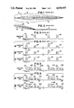
- pulses transmitted on the two lobes of an elevation or azimuth guidance system are transmitted as pulse pairs.
- a pulse pair consisting of an up pulse 26 followed by a down pulse 28 is repetitively transmitted.
- the amplitudes of the transmitted up pulse 26 and the transmitted down pulse 28 are equal so that when the aircraft is on course, the amplitudes of the pulses received will be equal, and an inequality of received pulses will indicate an off course condition.
- a typical azimuth ground station generates a pulse sequence similar to the one illustrated in FIG. 3 except that pairs of pulses consisting of a right pulse and a left pulse are repetitively generated.
- FIG. 4A shows a pair of pulses 26' and 28' correspond to the transmitted pulses 26 and 28.
- the difference in amplitude between the pulses 26' and 28' indicate that the aircraft is off course, i.e., within the lobe 20 (FIG. 2) since the amplitude of the pulse 26' is greater than the amplitude 28'.
- the difference in amplitude is processed by the processing system aboard the aircraft to provide an indication to the pilot as to the magnitude and direction of his deviation from the desired course. A similar indication can be provided for both azimuth and elevation deviations.
- one of the received pulses could be compressed relative to the other.
- failures that can cause pulse compression include insufficient local oscillator drive to the mixer of the receiving front end and a malfunction of the automatic gain control circuit.
- the amplitude of the pulse 26' is compressed relative to the amplitude of the pulse 28'.
- the compression may be even more severe, as illustrated in FIG. 4C wherein the magnitudes of the pulses 26' and 28' appear to be equal.
- the displayed guidance signal would indicate to the pilot that he is on course when he is really considerably off course, thus resulting in a dangerous situation.
- the pulse train transmitted by the ground station is modified to include a second pulse following (or preceding) each pulse in each transmitted pulse pair.
- a second reduced amplitude pulse 27 is inserted following the pulse 26, and a second pulse 29 is inserted following the pulse 28.
- the addiitional pulses are shown inserted following the pulses of the signal shown in FIG. 5, they can also be inserted prior to each pulse in the pulse pair.
- the inserted pulses 27 and 29 be of a different amplitude than the pulses 26 and 28 to provide a reference for detecting compression.
- the difference in amplitude between the pulses 26 and 27 and between the pulses 28 and 29 may be any detectable difference, for example 3 dB, and is illustrated as X dB in FIG.
- the amplitude differential between the larger and smaller pulses provides a reference by which the compression of a larger pulse relative to a smaller pulse may be measured. If no compression occurs in the receiving and pulse processing circuitry, the relative magnitudes of the received pulses will be the same as those of the transmitted pulses as illustrated in FIG. 6A. In FIG. 6A, the received pulses 26', 27', 28' and 29' correspond to the corresponding transmitting pulses 26, 27, 28 and 29. As is illustrated in FIG. 6A, the amplitude differential of X dB is maintained, thus indicating that no compression has occurred.
- the amplitude differential between the various pulses will not be maintained.
- the amplitude differential between the pulses 26' and 27' is less than X dB, thus indicating that compression has occurred.
- an indication of an invalid condition is generated to warn the pilot of a malfunction.
- a transmitter suitable for transmitting the pulse sequence according to the present invention is illustrated in FIG. 7 and generally designated by the reference numeral 30.
- the transmitting station 30 includes a pulse generator 32, an attenuator 34, an amplifier 36, a switching circuit 38, a pair of antennas 40 and 42 and a controller 44.
- the pulse generator To generate the desired pulse sequence to be transmitted, the pulse generator generates the paired pulses under the control of the controller 44.
- the pulses generated by the pulse generator 32 are bursts of radio frequency oscillations that may be of any suitable frequency, and in the present embodiment a frequency of 9.3 GHz is used.
- the pulses are applied to the attenuator 34 that attenuates one of the pulses in each pair and applies it to the amplifier 36 so that amplified pulses of unequal amplitude are applied to the switching circuit 38.
- the switching circuit 38 alternately applies the amplified signal to one of the antennas 40 and 42 under the control of the controller 44 so that successive pairs of pulses are coupled to different ones of the antennas 42 and 40.
- the transmitted pulses may be generated in a variety of ways other than those shown in FIG. 7.
- the antennas 40 and 42 are shown as being separate antennas, bu different driven elements of a single antenna may be emloyed.
- the switching circuit 38 is illustrated as a simple single pole double throw switch, but various electronic switching circuits may be employed.
- the controller utilizes an attenuator to vary the amplitudes of the transmitted pulses. This may be accomplished in a variety of ways including changing the amplitude of the pulses generated by the pulse generator 32, or by varying the gain of the amplifier 36.
- the attenuator 34 is shown to be ahead of the amplifier 36, it may be placed at the output of the amplifier 36, particularly if the amplifier 36 is nonlinear, or two attenuators may be used, one in series with each of the antennas 40 and 42.
- a receiving and pulse processing system suitable for use with the system according to the invention may take several embodiments, and an illustrative embodiment is generally designated by the reference numeral 50 in FIG. 8.
- the receiving system 50 comprises an antenna 52, a receiver 54, both of which may be of conventional design, a synchronization circuit 56, a switching circuit 58, an up pulse comparator 60, a down pulse comparator 62, an up-down pulse comparator 64 and a display 66. If desired, the system may be used to control an auto pilot 68. A similar system would be utilized to receive azimuth signals.
- signals are received by the antenna 52 by the receiver 54.
- the various pulses are preceded by a multiple pulse code, e.g., four pulses (not shown), that are digitally encoded in a conventional fashion to indicate whether up pulses, down pulses, left pulses or right pulses are to follow.
- the pulses are decoded by the receiver 54 and the synchronization circuit 56 and the output of the synchronization circuit 56 controls the switching circuit 58 to route the pulses to their appropriate comparators. For example, assming that the system 50 is used in an elevation guidance system, the up pulses would be routed to the up pulse comparator 60 and the down pulses would be routed to the down pulse comparator 62.
- the function of the up pulse comparator is to monitor the up pulses and to determine whether the differential between the up pulses 26' and 27' is maintained.
- the down pulse comparator serves the same function for the down pulses 28' and 29'. A similar comparison would be made in an azimuth signal receiving unit.
- the up pulses and down pulses are applied to the up-down pulse comparator 64.
- the function of the up-down pulse comparator 64 is to determine the relative amplitudes of the up and down pulses to provide location information, i.e., in the system of FIG. 8, the aircraft deviation above or below the glide slope. Either one or both of the pulses may be compared depending on whether a simple or a sophisticated system is desired. The results of the comparison are scaled and displayed on the display 66 which may be conventional glide slope display, and can also be used to control the auto pilot 68. A similar comparison would be made in an azimuth signal receiving unit.
- the up pulse comparator 60 or the down pulse comparator 62 which generates an invalid or an inhibit signal which is applied to the up-down pulse comparator and to the display (FIG. 8).
- the up-down pulse comparator is inhibited, to prevent erroneous information from being displayed, and an indication is displayed on the display 66 to illustrate to the pilot that a failure has occurred.
- a similar system may be used for the azimuth system.
- FIG. 8 As in the case of the transmitted shown in FIG. 7, various configurations of a suitable receiving and processing circuit may be utilized, with the particular embodiment illustrated in FIG. 8 being shown for illustrative purposes only.
Landscapes
- Engineering & Computer Science (AREA)
- Remote Sensing (AREA)
- Computer Networks & Wireless Communication (AREA)
- Physics & Mathematics (AREA)
- General Physics & Mathematics (AREA)
- Radar, Positioning & Navigation (AREA)
- Radar Systems Or Details Thereof (AREA)
- Traffic Control Systems (AREA)
Abstract
Description
Claims (6)
Priority Applications (5)
| Application Number | Priority Date | Filing Date | Title |
|---|---|---|---|
| US07/380,912 US4929957A (en) | 1989-07-17 | 1989-07-17 | Method and apparatus for detecting receiver compression in multiple lobe guidance systems |
| CA002017825A CA2017825A1 (en) | 1989-07-17 | 1990-05-30 | Method and apparatus for detecting receiver compression in multiple lobe guidance system |
| EP90911026A EP0434813A1 (en) | 1989-07-17 | 1990-06-05 | Method and apparatus for detecting receiver compression in multiple lobe guidance systems |
| JP2510362A JPH04500861A (en) | 1989-07-17 | 1990-06-05 | Method and apparatus for detecting receiver compression in a multilobe guiding device |
| PCT/US1990/003200 WO1991001504A1 (en) | 1989-07-17 | 1990-06-05 | Method and apparatus for detecting receiver compression in multiple lobe guidance systems |
Applications Claiming Priority (1)
| Application Number | Priority Date | Filing Date | Title |
|---|---|---|---|
| US07/380,912 US4929957A (en) | 1989-07-17 | 1989-07-17 | Method and apparatus for detecting receiver compression in multiple lobe guidance systems |
Publications (1)
| Publication Number | Publication Date |
|---|---|
| US4929957A true US4929957A (en) | 1990-05-29 |
Family
ID=23502937
Family Applications (1)
| Application Number | Title | Priority Date | Filing Date |
|---|---|---|---|
| US07/380,912 Expired - Fee Related US4929957A (en) | 1989-07-17 | 1989-07-17 | Method and apparatus for detecting receiver compression in multiple lobe guidance systems |
Country Status (5)
| Country | Link |
|---|---|
| US (1) | US4929957A (en) |
| EP (1) | EP0434813A1 (en) |
| JP (1) | JPH04500861A (en) |
| CA (1) | CA2017825A1 (en) |
| WO (1) | WO1991001504A1 (en) |
Citations (4)
| Publication number | Priority date | Publication date | Assignee | Title |
|---|---|---|---|---|
| US3911437A (en) * | 1974-01-21 | 1975-10-07 | Raytheon Co | Aircraft instrument landing system |
| US4193075A (en) * | 1978-06-29 | 1980-03-11 | Eaton Corporation | Low angle elevation guidance system |
| US4635064A (en) * | 1985-04-04 | 1987-01-06 | Sundstrand Data Control, Inc. | Microwave landing system |
| US4789864A (en) * | 1987-04-22 | 1988-12-06 | Eaton Corporation | Low elevation guidance system |
-
1989
- 1989-07-17 US US07/380,912 patent/US4929957A/en not_active Expired - Fee Related
-
1990
- 1990-05-30 CA CA002017825A patent/CA2017825A1/en not_active Abandoned
- 1990-06-05 JP JP2510362A patent/JPH04500861A/en active Pending
- 1990-06-05 EP EP90911026A patent/EP0434813A1/en not_active Withdrawn
- 1990-06-05 WO PCT/US1990/003200 patent/WO1991001504A1/en not_active Ceased
Patent Citations (4)
| Publication number | Priority date | Publication date | Assignee | Title |
|---|---|---|---|---|
| US3911437A (en) * | 1974-01-21 | 1975-10-07 | Raytheon Co | Aircraft instrument landing system |
| US4193075A (en) * | 1978-06-29 | 1980-03-11 | Eaton Corporation | Low angle elevation guidance system |
| US4635064A (en) * | 1985-04-04 | 1987-01-06 | Sundstrand Data Control, Inc. | Microwave landing system |
| US4789864A (en) * | 1987-04-22 | 1988-12-06 | Eaton Corporation | Low elevation guidance system |
Also Published As
| Publication number | Publication date |
|---|---|
| WO1991001504A1 (en) | 1991-02-07 |
| EP0434813A1 (en) | 1991-07-03 |
| CA2017825A1 (en) | 1991-01-17 |
| JPH04500861A (en) | 1992-02-13 |
Similar Documents
| Publication | Publication Date | Title |
|---|---|---|
| USRE32368E (en) | Collision avoidance system for aircraft | |
| US4319243A (en) | Airport-surveillance system | |
| US5579008A (en) | Electronic license plate apparatus and method | |
| US4429312A (en) | Independent landing monitoring system | |
| EP0537289B1 (en) | Monopulse processing systems | |
| US5196856A (en) | Passive SSR system utilizing P3 and P2 pulses for synchronizing measurements of TOA data | |
| US4196434A (en) | Surveillance system for collision avoidance of aircrafts using radar beacon | |
| US4161729A (en) | Beacon add-on subsystem for collision avoidance system | |
| US4138678A (en) | Integrity monitoring system for an aircraft navigation system | |
| JPS5932747B2 (en) | Method for controlling ground traffic at an airport using air traffic control transponders | |
| US4990921A (en) | Multi-mode microwave landing system | |
| US5689266A (en) | Testing apparatus for ATC transponder FAR compliance | |
| US4823139A (en) | Electronic countermeasure system | |
| US5361069A (en) | Airborne radar warning receiver | |
| EP0311312A2 (en) | Radar altimeter systems | |
| WO1990004795A1 (en) | Aircraft landing approach system | |
| EP0020104B1 (en) | Improvements in or relating to secondary surveillance radar | |
| US3122737A (en) | Apparatus for suppressing side-lobe interrogations in transponder beacon systems | |
| US4929957A (en) | Method and apparatus for detecting receiver compression in multiple lobe guidance systems | |
| US3159832A (en) | Anti-collision device for aircraft | |
| US3882497A (en) | Synchronizing techniques for an aircraft collision avoidance system | |
| JPH0317586A (en) | Method and device for remotely monitoring antenna radiation element of secondary monitor radar | |
| US4975708A (en) | Time domain electronic antenna beam shaping | |
| EP0056297A2 (en) | A navigation radar system | |
| US4363933A (en) | Automatic navigation station identifier and monitor |
Legal Events
| Date | Code | Title | Description |
|---|---|---|---|
| AS | Assignment |
Owner name: SUNDSTRAND DATA CONTROL, INC., 15001 N.E. 36TH ST. Free format text: ASSIGNMENT OF ASSIGNORS INTEREST.;ASSIGNOR:DAVIDSON, CHARLES W.;REEL/FRAME:005101/0803 Effective date: 19890710 |
|
| AS | Assignment |
Owner name: SUNDSTRAND CORPORATION Free format text: ASSIGNMENT OF ASSIGNORS INTEREST.;ASSIGNOR:SUNDSTRAND DATA CONTROL, INC. A CORP. OF DELAWARE;REEL/FRAME:005977/0032 Effective date: 19920113 Owner name: SUNDSTRAND CORPORATION, STATELESS Free format text: ASSIGNMENT OF ASSIGNORS INTEREST;ASSIGNOR:SUNDSTRAND DATA CONTROL, INC.;REEL/FRAME:005977/0032 Effective date: 19920113 |
|
| LAPS | Lapse for failure to pay maintenance fees | ||
| FP | Lapsed due to failure to pay maintenance fee |
Effective date: 19940529 |
|
| STCH | Information on status: patent discontinuation |
Free format text: PATENT EXPIRED DUE TO NONPAYMENT OF MAINTENANCE FEES UNDER 37 CFR 1.362 |